


Summary
Anchor bolts are used to connect structural and non-structural elements to concrete.[2] The connection can be made by a variety of different components: anchor bolts (also named fasteners), steel plates, or stiffeners. Anchor bolts transfer different types of load: tension forces and shear forces.[3]

A connection between structural elements can be represented by steel columns attached to a reinforced concrete foundation.[4] A common case of a non-structural element attached to a structural one is the connection between a facade system and a reinforced concrete wall.[5]
Types edit

Cast-in-place edit

The simplest – and strongest – form of anchor bolt is cast-in-place, with its embedded end consisting of a standard hexagonal head bolt and washer, 90-bend, or some sort of forged or welded flange (see also stud welding). The last are used in concrete-steel composite structures as shear connectors.[6] Other uses include anchoring machines to poured concrete floors[7] and buildings to their concrete foundations. Various typically disposable aids, mainly of plastic, are produced to secure and align cast-in-place anchors prior to concrete placement. Moreover, their position must also be coordinated with the reinforcement layout.[3] Different types of cast-in-place anchors might be distinguished:[3]
- Lifting inserts: used for lifting operations of plain or prestressed RC beams. The insert can be a threaded rod. See also bolt (climbing).
- Anchor channels: used in precast concrete connections.[8] The channel can be a hot-rolled or a cold-formed steel shape in which a T-shape screw is placed in order to transfer the load to the base material.
- Headed stud: consist of a steel plate with headed studs welded on (see also threaded rod).
- Threaded sleeves: consist of a tube with an internal thread which is anchored back into the concrete.
For all the type of the cast-in-place anchors, the load-transfer mechanisms is the mechanical interlock,[3] i.e. the embedded part of the anchors in concrete transfers and the applied load (axial or shear) via bearing pressure at the contact zone. At failure conditions, the level of bearing pressure can be higher than 10 times the concrete compressive strength, if a pure tension force is transferred.[3] Cast-in-place type anchors are also utilized in masonry applications, placed in wet mortar joints during the laying of brick and cast blocks (CMUs).
Post-installed edit
Post-installed anchors can be installed in any position of hardened concrete after a drilling operation.[3] A distinction is made according to their principle of operation.
Mechanical expansion anchors edit

The force-transfer mechanism is based on friction mechanical interlock guaranteed by expansion forces. They can be further divided into two categories:[3]
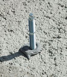
- torque controlled: the anchor is inserted into the hole and secured by applying a specified torque to the bolt head or nut with a torque wrench. A particular sub-category of this anchor is called wedge type. As shown in the figure, tightening the bolt results in a wedge being driven up against a sleeve, which expands it and causes it to compress against the material it is being fastened to.
- displacement controlled: usually consist of an expansion sleeve and a conical expansion plug, whereby the sleeve is internally threaded to accept a threaded element.
Undercut anchors edit
The force-transfer mechanism is based on mechanical interlock. A special drilling operation allows to create a contact surface between the anchor head and the hole's wall where bearing stresses are exchanged.
Bonded anchors edit
Bonded anchors are also referred as adhesive anchors[9] or chemical anchors. The anchoring material is an adhesive (also called mortar)[3] usually consisting of epoxy, polyester, or vinylester resins.[1]
In bonded anchors, the force-transfer mechanism is based on bond stresses provided by binding organic materials. Both ribbed bars and threaded rods can be used and a change of the local bond mechanism can be appreciated experimentally. In ribbed bars the resistance is prevalently due to shear behavior of concrete between the ribs whereas for threaded rods friction prevails (see also anchorage in reinforced concrete).[10]
The performance of this anchor's types in terms of 'load-bearing capacity', especially under tension loads, is strictly related to the cleaning condition of the hole. Experimental results[3] showed that the reduction of the capacity is up to 60%. The same applies also for moisture condition of concrete, for wet concrete the reduction is of 20% using polyester resin. Other issues are represented by high temperature behavior[11] and creep response.[12]
Screw anchors edit
The force-transfer mechanism of the screw anchor is based on concentrated pressure exchange between the screw and concrete through the pitches.
Plastic anchors edit

Their force-transfer mechanism is similar to mechanical expansion anchors. A torque moment is applied to a screw which is inserted in a plastic sleeve. As the torque is applied the plastic expands the sleeve against the sides of the hole acting as expansion force.
Tapcon screws edit
Tapcon screws are a popular anchor that stands for self tapping (self threading) concrete screw. Larger diameter screws are referred to as LDT's. This type of fastener requires a pre-drilled hole—using a Tapcon drillbit—and are then screwed into the hole using a standard hex or phillips bit. These screws are often blue, white, or stainless.[13] They are also available in versions for marine or high stress applications.
Powder-actuated anchors edit
They act transferring the forces via mechanical interlock. This fastening technology is used in steel-to-steel connection, for instance to connect cold-formed profiles. A screw is inserted into the base material via a gas actuated gas gun. The driving energy is usually provided by firing a combustible propellant in powder form.[14] The fastener's insertion provokes the plastic deformation of the base material which accommodates the fastener's head where the force transfer takes place.
Mechanical behavior edit
Modes of failure in tension edit
Anchors can fail in different way when loaded in tension:[3]
- Steel failure: the weak part of the connection is represented by the rod. The failure corresponds to the tensile break-out of steel as in case of tensile testing. In this case, concrete base material might be undamaged.
- Pull-out: the anchor is pulled out from the drilled hole partially damaging the surrounding concrete. When the concrete is damaged the failure is also indicated as pull-through.
- Concrete cone: after reaching the load-bearing capacity a cone shape is formed. The failure is governed by crack growth in concrete.[15] This kind of failure is typical in pull-out test.[16][17]
- Splitting failure: failure is characterized by a splitting crack which divides the base material into two parts. This kind of failure occurs when the dimensions of the concrete component are limited or the anchor is installed close to an edge.
- Blow-out failure: failure is characterized by the lateral spalling of concrete in the proximity of the anchor's head. This kind of failure occurs for anchors (prevalently cast-in-place) installed near the edge of the concrete element.
In design verification under ultimate limit state, codes prescribe to verify all the possible failure mechanisms.[18]
-
![Steel Failure[1]](//upload.wikimedia.org/wikipedia/commons/thumb/e/e9/Steel_Failure.png/109px-Steel_Failure.png) Steel Failure[1]
Steel Failure[1] -
![Concrete Cone Failure[1]](//upload.wikimedia.org/wikipedia/commons/thumb/1/10/Concrete_Cone_Failure.png/120px-Concrete_Cone_Failure.png) Concrete Cone Failure[1]
Concrete Cone Failure[1] -
![Pull-Out Failure[1]](//upload.wikimedia.org/wikipedia/commons/thumb/b/b0/Pull-Out_failure.png/120px-Pull-Out_failure.png) Pull-Out Failure[1]
Pull-Out Failure[1] -
![Pull-Through Failure[1]](//upload.wikimedia.org/wikipedia/commons/thumb/6/6e/Pull-Through_failure.png/120px-Pull-Through_failure.png) Pull-Through Failure[1]
Pull-Through Failure[1] -
![Blow-Out Failure[1]](//upload.wikimedia.org/wikipedia/commons/thumb/1/10/Blow_Out_Failure.png/120px-Blow_Out_Failure.png) Blow-Out Failure[1]
Blow-Out Failure[1] -
 Splitting Failure
![Steel Failure[1]](http://upload.wikimedia.org/wikipedia/commons/thumb/e/e9/Steel_Failure.png/109px-Steel_Failure.png)
![Concrete Cone Failure[1]](http://upload.wikimedia.org/wikipedia/commons/thumb/1/10/Concrete_Cone_Failure.png/120px-Concrete_Cone_Failure.png)
![Pull-Out Failure[1]](http://upload.wikimedia.org/wikipedia/commons/thumb/b/b0/Pull-Out_failure.png/120px-Pull-Out_failure.png)
![Pull-Through Failure[1]](http://upload.wikimedia.org/wikipedia/commons/thumb/6/6e/Pull-Through_failure.png/120px-Pull-Through_failure.png)
![Blow-Out Failure[1]](http://upload.wikimedia.org/wikipedia/commons/thumb/1/10/Blow_Out_Failure.png/120px-Blow_Out_Failure.png)

Modes of failure in shear edit
Anchors can fail in different way when loaded in shear:[3]
- Steel failure: the rod reaches the yielding capacity then rupture occurs after development of large deformations.
- Concrete edge: a semi-conical fracture surface develops originating from the point of bearing up to the free surface. This type of failure occurs, for an anchor in the proximity of the edge of the concrete member.
- Pry-out: a semi-conical fracture surface develops characterize the failure. The pryout mechanism for cast-in anchors usually occurs with very short, stocky studs.[19] The studs are typically so short and stiff that under a direct shear load, they bend causing contemporarily crushing in front of the stud and a crater of concrete behind.
In design verification under ultimate limit state, codes prescribe to verify all the possible failure mechanisms.[18]
![Concrete Edge failure[1]](http://upload.wikimedia.org/wikipedia/commons/thumb/8/80/Concrete_Edge_failure.png/109px-Concrete_Edge_failure.png)
![Pry-Out failure[1]](http://upload.wikimedia.org/wikipedia/commons/thumb/2/28/Pry_Out_Failure.png/120px-Pry_Out_Failure.png)
Combined tension/shear edit
When contemporarily tension and shear load are applied to an anchor the failure occurs earlier (at a less load-bearing capacity) with respect the un-coupled case. In current design codes a linear interaction domain is assumed.[20]
Group of anchors edit

In order to increase the load-carrying capacity anchors are assembled in group, moreover this allow also to arrange a bending moment resisting connection. For tension and shear load, the mechanical behavior is markedly influenced by (i) the spacing between the anchors and (ii) the possible difference in the applied forces.[22]
Service load behavior edit
Under service loads (tension and shear) anchor's displacement must be limited. The anchor performance (load-carrying capacity and characteristic displacements) under different loading condition is assessed experimentally, then an official document is produced by technical assessment body.[23] In design phase, the displacement occurring under the characteristic actions should be not larger than the admissible displacement reported in the technical document.
Seismic load behavior edit
Under seismic loads and there would be the possibility that an anchor is contemporarily (i) installed in a crack and (ii) subjected to inertia loads proportional both to the mass and the acceleration of the attached element (secondary structure) to the base material (primary structure).[2] The load conditions in this case can be summarized as follow:
- Pulsating Axial load: force aligned with the anchor's axis, positive in case of pullout condition and zero in case of pushing-in.
- Reverse Shear load (also named “alternate shear”): force perpendicular to the anchor's axis, positive and negative depending on an arbitrary sign convention.
- Cyclic Crack (also named “crack movement”): RC primary structure undergoes in severe damage condition[24] (i.e. cracking) and the most un-favorable case for anchor performance is when the crack plane contains the anchor's axis and the anchor is loaded by a positive axial force (constant during crack cycles).[3]
Exceptional loads behavior edit
Exceptional loads differ from ordinary static loads for their rise time. High displacement rates are involved in impact loading. Regarding steel to concrete connections, some examples consist in collision of vehicle on barriers connected to concrete base and explosions. Apart from these extraordinary loads, structural connections are subjected to seismic actions, which rigorously have to be treated via dynamic approach. For instance, seismic pull-out action on anchor can have 0.03 seconds of rise time. On the contrary, in a quasi-static test, 100 second may be assumed as time interval to reach the peak load. Regarding the concrete base failure mode: Concrete cone failure loads increase with elevated loading rates with respect the static one.[25]
Designs edit
-
 Wedge type - 1
 -
 Expansion type
 -
 Sleeve type
 -
 Wedge type - 2
 -
 Bonded Anchor
 -
 Concrete Screw


See also edit
References edit
- ^ a b c d e f g h i j Cook, Ronald; Doerr, G T; Klingner, R.E. (2010). Design Guide For Steel To Concrete Connections. University Of Texas Austin.
- ^ a b Hoehler, Matthew S.; Eligehausen, Rolf (2008). "Behavior and testing of anchors in simulated seismic cracks". ACI Structural Journal. 105 (3): 348–357. ISSN 0889-3241..
- ^ a b c d e f g h i j k l Mallèe, Rainer; Eligehausen, Rolf; Silva, John F (2006). Anchors In Concrete Structures. Ernst&Shon. ISBN 978-3433011430.
- ^ Fisher, James M. (2006). Base Plate and Anchor Rod Design.
- ^ IStructE (1988). Aspects of Cladding. London.
{{cite book}}: CS1 maint: location missing publisher (link) - ^ Standard Handbook of Engineering Calculations. McGraw-Hill. 2004.
- ^ Bhantia, K.G. (2008). Foundations for Industrial Machines – Handbook for practising engineering. New Delhi: D-CAD. ISBN 978-81-906032-0-1.
- ^ Bachmann, Hubert; Steinle, Alfred (2012). Precast Concrete Structures. Berlin: Ernst&Shon. ISBN 978-0-7506-5084-7.
- ^ Sasse, H.R. (1986). Adhesion between polymers and concrete. Springer. ISBN 978-0-412-29050-3.
- ^ Reinhardt, Hans-Wolf (1982). Concrete under impact loading tensile strength and bond. Delft: Delft University.
- ^ Raouffard, Mohammad Mahdi; Nishiyama, Minehiro (2018). "Idealization of bond stress-slip relationship at elevated temperatures based on pullout tests". ACI Structural Journal. 115 (2). doi:10.14359/51701120. ISSN 0889-3241.
- ^ Nilforoush, Rasoul; Nilsson, Martin; Söderlind, Gunnar; Elfgren, Lennart (2016). "Long-Term Performance of Adhesive Bonded Anchors". ACI Structural Journal. 113 (2): 251–262. doi:10.14359/51688060..
- ^ All About Tapcon Screws; Do It Yourself website online; accessed April 2019
- ^ Beck, Hermann; Siemers, Michael; Reuter, Martin (2011). Powder-actuared fasteners and fastening screws in steel construction. Ernst&Shon. ISBN 978-3-433-02955-8.
- ^ Eligehausen, Rolf; Sawade, G. (1989). "A fracture mechanics based description of the pull-out behavior of headed studs embedded in concrete". Fracture Mechanics of Concrete Structures: 281–299. doi:10.18419/opus-7930.
- ^ Bungey, J.H.; Millard, S.G. (1996). Testing of Concrete in Structures. London: Blackie Academic & Professional. ISBN 0-203-48783-4.
- ^ Stone, William C.; Carino, Nicholas J (1984). "Deformation and Failure in Large-Scale Pullout Tests". ACI Structural Journal (80).
- ^ a b ACI (2014). ACI 318-14 Building code requirements for structural concrete. Vol. 22. American Concrete Institute. ISBN 978-0-87031-930-3. JSTOR 3466335.
- ^ Anderson, Neal S; Meinheit, Donald F (2005). "Pryout Capacity of Cast-In Headed Stud Anchors". PCI Journal. 50 (2): 90–112. doi:10.15554/pcij.03012005.90.112. ISSN 0887-9672.
- ^ ACI (2004). "ACI 349.2 Guide to the Concrete Capacity Design ( CCD ) Method — Embedment Design Examples". Concrete (Ccd): 1–77.
- ^ Doerr, G T; Klingner, R.E. (1989). Adhesive Anchors Behaviour And Spacing Requirements. University Of Texas Austin.
- ^ Mahrenholtz, Philipp; Eligehausen, Rolf (2010). Behavior of anchor groups installed in cracked concrete under simulated seismic actions (PDF). Proceeding of the Conference on Fracture Mechanics of Concrete Structures (FraMCoS 7). Jeju, S. Korea.
- ^ "How to find a TAB". EOTA. Archived from the original on 2018-06-14. Retrieved 2018-06-14.
- ^ Fardis, Michael N. (2009). Seismic Design, Assessment and Retrofitting of Concrete Buildings. London: Springer. ISBN 978-1-4020-9841-3.
- ^ Solomos, George. Testing of Anchorages in Concrete under Dynamic Loading. Ispra: Joint research Centre.
- ^ "ETA seismic approval concrete screw". Joker Industrial.