


Summary
An aileron (French for "little wing" or "fin") is a hinged flight control surface usually forming part of the trailing edge of each wing of a fixed-wing aircraft.[1] Ailerons are used in pairs to control the aircraft in roll (or movement around the aircraft's longitudinal axis), which normally results in a change in flight path due to the tilting of the lift vector. Movement around this axis is called 'rolling' or 'banking'.


Considerable controversy exists over credit for the invention of the aileron. The Wright brothers and Glenn Curtiss fought a years-long legal battle over the Wright patent of 1906, which described a method of wing-warping to achieve lateral control. The brothers prevailed in several court decisions which found that Curtiss's use of ailerons violated the Wright patent. Ultimately, the First World War compelled the U.S. Government to legislate a legal resolution. A much earlier aileron concept was patented in 1868 by British scientist Matthew Piers Watt Boulton, based on his 1864 paper On Aërial Locomotion.
History edit

The name "aileron", from French, meaning "little wing", also refers to the extremities of a bird's wings used to control their flight.[2][3] It first appeared in print in the 7th edition of Cassell's French-English Dictionary of 1877, with its lead meaning of "small wing".[4] In the context of powered airplanes it appears in print about 1908. Prior to that, ailerons were often referred to as rudders, their older technical sibling, with no distinction between their orientations and functions, or more descriptively as horizontal rudders (in French, gouvernails horizontaux). Among the earliest printed aeronautical use of 'aileron' was that in the French aviation journal L'Aérophile of 1908.[5]
Ailerons had more or less completely supplanted other forms of lateral control, such as wing warping, by about 1915, well after the function of the rudder and elevator flight controls had been largely standardised. Although there were previously many conflicting claims over who first invented the aileron and its function, i.e., lateral or roll control,[5] the flight control device was invented and described by the British scientist and metaphysicist Matthew Piers Watt Boulton in his 1864 paper On Aërial Locomotion. He was the first to patent an aileron control system in 1868.[5][6][7][8]
Boulton's description of his lateral flight control system was "the first record we have of appreciation of the necessity for active lateral control as distinguished from [passive lateral stability].... With this invention of Boulton's we have the birth of the present-day three torque method of airborne control" as was praised by Charles Manly.[9] This was also endorsed by C.H. Gibbs-Smith.[10][11] Boulton's British patent, No. 392 of 1868, issued about 35 years before ailerons were "reinvented" in France, became forgotten and lost from sight until after the flight control device was in general use.[12][Note 1] Gibbs-Smith stated on several occasions that if the Boulton patent had been revealed at the time of the Wright brothers' legal filings, they might not have been able to claim priority of invention for the lateral control of flying machines. The fact that the Wright brothers were able to gain a patent in 1906 did not invalidate Boulton's lost and forgotten invention.[10]
Ailerons were not used on manned aircraft until they were employed on Robert Esnault-Pelterie's glider in 1904,[5][13] although in 1871 a French military engineer, Charles Renard, built and flew an unmanned glider incorporating ailerons on each side (which he termed 'winglets'), activated by a Boulton-style pendulum controlled single-axis autopilot device.[14]
The pioneering U.S. aeronautical engineer Octave Chanute published descriptions and drawings of the Wright brothers' 1902 glider in the leading aviation periodical of the day, L'Aérophile, in 1903. This prompted Esnault-Pelterie, a French military engineer, to build a Wright-style glider in 1904 that used ailerons in lieu of wing warping.[5] The French journal L'Aérophile then published photos of the ailerons on Esnault-Pelterie's glider which were included in his June 1905 article, and its ailerons were widely copied afterward.[8][15][16]
The Wright brothers used wing warping instead of ailerons for roll control on their glider in 1902, and about 1904 their Flyer II was the only aircraft of its time able to do a coordinated banked turn. During the early years of powered flight the Wrights had better roll control on their designs than airplanes that used movable surfaces. From 1908, as aileron designs were refined it became clear that ailerons were much more effective and practical than wing warping. Ailerons also had the advantage of not weakening the airplane's wing structure as did the wing warping technique,[5] which was one reason for Esnault-Pelterie's decision to switch to ailerons.[16]
By 1911 most biplanes used ailerons rather than wing warping—by 1915 ailerons had become almost universal on monoplanes as well. The U.S. Government, frustrated by the lack of its country's aeronautical advances in the years leading up to World War I, enforced a patent pool effectively putting an end to the Wright brothers patent war.[17][18][19] The Wright company quietly changed its aircraft flight controls from wing warping to the use of ailerons at that time as well.
Other early aileron designers edit
Others who were previously thought to have been the first to introduce ailerons included:
- American John J. Montgomery included spring-loaded trailing edge flaps on his second glider (1885): these were operable by the pilot as ailerons. In 1886 his third glider design used rotation of the entire wing rather than just a trailing edge portion for roll control. By his own accounts all of these changes in addition to his use of an elevator for pitch control provided "entire control of the machine in the wind, preventing it from upsetting."[20]
- New Zealander Richard Pearse reputedly made a powered flight in a monoplane that included small ailerons as early as 1902, but his claims are controversial—and sometimes inconsistent—and, even by his own reports, his aircraft were not well controlled.

- In 1906 Alberto Santos-Dumont's 14-bis was one of the earliest (if not the earliest) engine-powered, aileron-equipped aircraft to fly, as it was modified to have added octagonal-planform interplane ailerons in its outermost wing bays on November 12 of that year for its concluding flight sessions at the Chateau de Bagatelle's grounds; but those roll control surfaces were not true "trailing-edge" ailerons hinged directly to the wing panels' framework—for the 14-bis, these were instead pivoted around a horizontal axis centred on the forward outboard interplane struts, and protruded forward past the wings' leading edges - said to be very much like those on Robert Esnault-Pelterie's 1904 biplane glider design.[21]
- On May 18, 1908, engineer and aircraft designer Frederick Baldwin, a member of the Aerial Experiment Association headed by Alexander Graham Bell, flew their first aileron-controlled aircraft, the AEA White Wing,[7] which was later copied by the U.S. aeronautical pioneer Glenn Curtiss[22] the same year, with the AEA June Bug.
- Henry Farman's ailerons on his 1909 Farman III were the first to resemble ailerons on modern aircraft as they were hinged directly to the wing planform structure, and thus were viewed as having a reasonable claim as the ancestor of the modern-day aileron.[7]
- Wingtip ailerons were also used on the contemporary Bleriot VIII—the first known flightworthy aircraft to use the joystick and rudder bar pioneering form of modern flight controls[23] in a single airframe, and the 1911-vintage Curtiss Model D pusher biplane had spanwise rectangular interplane ailerons of a similar nature to those on the final form of the Santos-Dumont 14-bis,[16] but mounted on, and pivoted from the outer rear interplane struts instead.
- Another very late contestant included the American, William Whitney Christmas, who claimed to have invented the aileron in the 1914 patent for what would become the Christmas Bullet which was built in 1918.[24] Both "Bullet" prototypes crashed during their first "flights" when their wings broke off in flight due to flutter as a result of being deliberately unbraced.
Patents and lawsuits edit
The Wright Brothers' Ohio patent attorney Henry Toulmin filed an expansive patent application and on May 22, 1906, the brothers were granted U.S. Patent 821393.[25] The patent's importance lay in its claim of a new and useful method of controlling an airplane. The patent application included the claim for the lateral control of aircraft flight that was not limited to wing warping, but through any manipulation of the "....angular relations of the lateral margins of the airplanes [wings].... varied in opposite directions". Thus the patent explicitly stated that other methods besides wing-warping could be used for adjusting the outer portions of an airplane's wings to different angles on its right and left sides to achieve lateral roll control. John J. Montgomery was granted U.S. Patent 831173 [26] at nearly the same time for his methods of wing warping. Both the Wright Brothers patent and Montgomery's patent were reviewed and approved by the same patent examiner at the United States Patent Office, William Townsend.[27] At the time Townsend indicated that both methods of wing warping were invented independently and were sufficiently different to each justify their own patent award.
Multiple U.S. court decisions favoured the expansive Wright patent, which the Wright Brothers sought to enforce with licensing fees starting from $1,000 per airplane,[5][28] and said to range up to $1,000 per day.[29] According to Louis S. Casey, a former curator of the Smithsonian Air & Space Museum in Washington, D.C., and other researchers, due to the patent they had received the Wrights stood firmly on the position that all flying using lateral roll control, anywhere in the world, would only be conducted under license by them.[29]
The Wrights subsequently became embroiled with numerous lawsuits they launched against aircraft builders who used lateral flight controls, and the brothers were consequently blamed for playing "...a major role in the lack of growth and aviation industry competition in the United States comparative to other nations like Germany leading up to and during World War I".[28] Years of protracted legal conflict ensued with many other aircraft builders until the U.S. entered World War I, when the government imposed a legislated agreement among the parties which resulted in royalty payments of 1% to the Wrights.[29]
Ongoing controversy edit
There are still conflicting claims today over who first invented the aileron. Other 19th century engineers and scientists, including Charles Renard, Alphonse Pénaud, and Louis Mouillard, had described similar flight control surfaces. Another technique for lateral flight control, wing warping, was also described or experimented with by several people including Jean-Marie Le Bris, John Montgomery, Clement Ader, Edson Gallaudet, D.D. Wells, and Hugo Mattullath.[5][30] Aviation historian C.H. Gibbs-Smith wrote that the aileron was "....one of the most remarkable inventions... of aeronautical history, which was immediately lost sight of".[5]
In 1906 the Wright brothers obtained a patent not for the invention of an airplane (which had existed for a number of decades in the form of gliders) but for the invention of a system of aerodynamic control that manipulated a flying machine's surfaces, including lateral flight control,[31] although rudders, elevators and ailerons had previously been invented.
Flight dynamics edit

Pairs of ailerons are typically interconnected so that when one is moved downward, the other is moved upward: the down-going aileron increases the lift on its wing while the up-going aileron reduces the lift on its wing, producing a rolling (also called 'banking') moment about the aircraft's longitudinal axis (which extends from the nose to the tail of an airplane).[32] Ailerons are usually situated near the wing tip, but may sometimes also be situated nearer the wing root. Modern airliners may also have a second pair of ailerons on their wings, with the two positions distinguished by the terms 'outboard aileron' and 'inboard aileron'.
An unwanted side effect of aileron operation is adverse yaw—a yawing moment in the opposite direction to the roll. Using the ailerons to roll an aircraft to the right produces a yawing motion to the left. As the aircraft rolls, adverse yaw is caused partly by the change in drag between the left and right wing. The rising wing generates increased lift, which causes increased induced drag. The descending wing generates reduced lift, which causes reduced induced drag. Profile drag caused by the deflected ailerons may add further to the difference, along with changes in the lift vectors as one rotates back while the other rotates forward.

In a coordinated turn, adverse yaw is effectively compensated by the use of the rudder, which results in a sideforce on the vertical tail that opposes the adverse yaw by creating a favorable yawing moment. Another method of compensation is 'differential ailerons', which have been rigged so that the down-going aileron deflects less than the up-going one. In this case the opposing yaw moment is generated by a difference in profile drag between the left and right wingtips. Frise ailerons accentuate this profile drag imbalance by protruding beneath the wing of an upward-deflected aileron, most often by being hinged slightly behind the leading edge and near the bottom of the surface, with the lower section of the aileron surface's leading edge protruding slightly below the wing's undersurface when the aileron is deflected upwards, substantially increasing profile drag on that side. Ailerons may also be designed to use a combination of these methods.[32]
With ailerons in the neutral position, the wing on the outside of the turn develops more lift than the opposite wing due to the variation in airspeed across the wing span, which tends to cause the aircraft to continue to roll. Once the desired angle of bank (degree of rotation about the longitudinal axis) has been obtained, the pilot uses opposite aileron to prevent the angle of bank from increasing due to this variation in lift across the wing span. This minor opposite use of the control must be maintained throughout the turn. The pilot also uses a slight amount of rudder in the same direction as the turn to counteract adverse yaw and to produce a "coordinated" turn wherein the fuselage is parallel to the flight path. A simple gauge on the instrument panel called the slip indicator, also known as "the ball", indicates when this coordination is achieved.[32]
Aileron components edit
Horns and aerodynamic counterbalances edit

Particularly on larger or faster aircraft, control forces may be extremely heavy. Borrowing a discovery from boats that extending a control surface's area forward of the hinge lightens the forces needed first appeared on ailerons during World War I when ailerons were extended beyond the wingtip and provided with a horn ahead of the hinge. Known as overhung ailerons, possibly the best known examples are the Fokker Dr.I and Fokker D.VII. Later examples brought the counterbalance in line with the wing to improve control and reduce drag. This is seen less often now, due to the Frise type aileron[clarification needed] which provides the same benefit.[citation needed]
Trim tabs edit
Trim tabs are small movable sections resembling scaled down ailerons located at or near the trailing edge of the aileron. On most propeller powered aircraft, the rotation of the propeller(s) induces a counteracting roll movement due to Newton's third law of motion, in that every action has an equal and opposite reaction. To relieve the pilot of having to provide continuous pressure on the stick in one direction (which causes fatigue) trim tabs are provided to adjust or trim out the pressure needed against any unwanted movement. The tab itself is deflected in relation to the aileron, causing the aileron to move in the opposite direction. Trim tabs come in two forms, adjustable and fixed. A fixed trim tab is manually bent to the required amount of deflection, while the adjustable trim tab can be controlled from within the cockpit so that different power settings or flight attitudes can be compensated for. Some large aircraft from the 1950s (including the Canadair Argus) used free floating control surfaces that the pilot controlled only through the deflection of trim tabs, in which case additional tabs were also provided to fine-tune the control to provide straight and level flight.[citation needed]
Spades edit

Spades are flat metal plates, usually attached to the aileron lower surface, ahead of the aileron hinge, by a lever arm. They reduce the force needed by the pilot to deflect the aileron and are often seen on aerobatic aircraft. As the aileron is deflected upward, the spade produces a downward aerodynamic force, which tends to rotate the whole assembly so as to further deflect the aileron upward. The size of the spade (and its lever arm) determines how much force the pilot needs to apply to deflect the aileron. A spade works in the same manner as a horn but is more efficient due to the longer moment arm.[citation needed]
Mass balance weights edit

To increase the speed at which control surface flutter (aeroelastic flutter) might become a risk, the center of gravity of the control surface is moved towards the hinge-line for that surface. To achieve this, lead weights may be added to the front of the aileron. In some aircraft the aileron construction may be too heavy to allow this system to work without an excessive increase in the weight of the aileron. In this case, the weight may be added to a lever arm to move the weight well out in front to the aileron body. These balance weights are tear drop shaped (to reduce drag), which make them appear quite different from spades, although both project forward and below the aileron. In addition to reducing the risk of flutter, mass balances also reduce the stick forces required to move the control surface in maneuvers.[citation needed]
Aileron fences edit
Some aileron designs, particularly when fitted on swept wings, include fences like wing fences flush with their inboard plane, in order to suppress some of the spanwise component of the airflow running on the top of the wing, which tends to disrupt the laminar flow above the aileron, when deflected downwards.[citation needed]
Types of ailerons edit
Single acting ailerons edit
Used during aviation's pre-war "pioneer era" and into the early years of the First World War, these ailerons were each controlled by a single cable, which pulled the aileron up. When the aircraft was at rest, the ailerons hung vertically down. This type of aileron was used on the Farman III biplane 1909 and the Short 166. A "reverse" version of this, utilizing wing-warping, existed on the later version of the Santos-Dumont Demoiselle, which only warped the wingtips "downward".[33] One of the disadvantages of this setup was a greater tendency to yaw than even with basic interconnected ailerons.[34] During the 1930s a number of light aircraft used single acting controls but used springs to return the ailerons to their neutral positions when the stick was released.
Wingtip ailerons edit
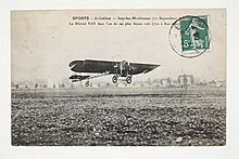
Used on the first-ever airframe to have the combination of "joystick/rudder-bar" controls that directly led to the modern flight control system, the Blériot VIII in 1908,[35] some designs of early aircraft used "wingtip" ailerons, where the entire wingtip was rotated to achieve roll control as a separate, pivoting roll-control surface—the AEA June Bug used a form of these, with both the experimental German Fokker V.1 of 1916 and the earlier versions of the Junkers J 7 all-duralumin metal demonstrator monoplane using them—the J 7 led directly to the Junkers D.I all-duralumin metal German fighter design of 1918, which had conventionally hinged ailerons. The main problem with this type of aileron is the dangerous tendency to stall if used aggressively, especially if the aircraft is already in danger of stalling, hence the use primarily on prototypes, and their replacement on production aircraft with more conventional ailerons.
Frise ailerons edit

Engineer Leslie George Frise (1897–1979) of the Bristol Aeroplane Company[37] developed an aileron shape that is pivoted at about its 25 to 30% chord line and near its bottom surface [1], in order to decrease stick forces as aircraft became faster during the 1930s. When the aileron is deflected up (to make its wing go down), the leading edge of the aileron starts to protrude below the underside of the wing into the airflow beneath the wing. The moment of the leading edge in the airflow helps to move up the trailing edge, which decreases the stick force. The down moving aileron also adds energy to the boundary layer. The edge of the aileron directs air flow from the underside of the wing to the upper surface of the aileron, thus creating a lifting force added to the lift of the wing. This reduces the needed deflection of the aileron. Both the Canadian Fleet Model 2 biplane of 1930 and the 1938 popular US Piper J-3 Cub monoplane possessed Frise ailerons as designed and helped introduce them to a wide audience.
A claimed benefit of the Frise aileron is the ability to counteract adverse yaw. To do so, the leading edge of the aileron has to be sharp or bluntly rounded, which adds significant drag to the upturned aileron and helps counterbalance the yaw force created by the other aileron turned down. This can add some unpleasant, nonlinear effect and/or potentially dangerous aerodynamic vibration (flutter).[38] Adverse yaw moment is basically countered by aircraft yaw stability and also by the use of differential aileron movement.[39]
The Frise-type aileron also forms a slot, so air flows smoothly over the lowered aileron, making it more effective at high angles of attack. Frise-type ailerons may also be designed to function differentially. Like the differential aileron, the Frise-type aileron does not eliminate adverse yaw entirely. Coordinated rudder application is still needed when ailerons are applied.[36]
Differential ailerons edit

By careful design of the mechanical linkages, the up aileron can be made to deflect more than the down aileron (e.g., US patent 1,565,097).[40] This helps reduce the likelihood of a wing tip stall when aileron deflections are made at high angles of attack. In addition, the consequent differential in drag reduces adverse yaw[41] (as also discussed above). The idea is that the loss of lift associated with the up aileron carries no penalty while the increase in lift associated with the down aileron is minimized. The rolling couple on the aircraft is always the difference in lift between the two wings. A designer at de Havilland invented a simple and practical linkage and their de Havilland Tiger Moth classic British biplane became one of the best-known aircraft, and one of the earliest, to use differential ailerons.[42]
Roll control without ailerons edit
Wing warping edit
On the earliest Pioneer Era aircraft, such as the Wright Flyer and the later, 1909-origin Blériot XI and Etrich Taube,[43] lateral control was effected by twisting the outboard portion of the wing so as to increase or decrease lift by changing the angle of attack. This had the disadvantages of stressing the structure, being heavy on the controls, and of risking stalling the side with the increased angle of attack during a maneuver. By 1916, most designers had abandoned wing warping in favor of ailerons. Researchers at NASA and elsewhere have been taking a second look at wing warping again, although under new names. The NASA version is the X-53 Active Aeroelastic Wing while the United States Air Force tested the Adaptive Compliant Wing.[44][45]
Differential spoilers edit
Spoilers are devices that when extended into the airflow over a wing, disrupt the airflow and reduce the amount of lift generated. Many modern aircraft designs, especially jet aircraft, use spoilers in lieu of, or to supplement ailerons, such as the F4 Phantom II and Northrop P-61 Black Widow, which had almost full width flaps (there were very small conventional ailerons at the wingtips as well).
Roll induced by rudder edit
All aircraft with dihedral have some form of yaw-roll coupling to promote stability. Common trainers like the Cessna 152/172 series can be roll controlled with rudder alone. The rudder of the Boeing 737 has more roll authority over the aircraft than the ailerons at high angles of attack. This led to two notable accidents when the rudder jammed in the fully deflected position causing rollovers (see Boeing 737 rudder issues).
Some aircraft such as the Fokker Spin and model gliders lack any type of lateral control. Those aircraft use a higher amount of dihedral than conventional aircraft. Deflecting the rudder gives yaw and a lot of differential wing lift, giving a yaw induced roll moment. This type of control system is most commonly seen in the Flying Flea family of small aircraft and on simpler 2-function (pitch and yaw control) glider models or 3-function (pitch, yaw and throttle control) model powered aircraft, such as radio-controlled versions of "Old Timer" free-flight engine-powered model aircraft.
Other methods edit
- Weight-shift control is widely used in hang gliders, powered hang gliders, and ultralight aircraft.
- Flight with disabled controls has been successful in a small number of aviation incidents.
- Reaction control valves as used in the Harrier family of military aircraft.
- Top rudder: this device was fitted to the British Army Aeroplane No 1. It comprised an all-flying fin mounted above the upper wing and pivoted about a vertical axis. In operation it applied a side force approximately above the centre of pressure, causing the craft to roll. The design also had all-flying ailerons between the wing planes, but these were removed at the time it made the first official flight of a British aircraft and roll control during the flight was achieved solely by use of the top rudder.[46]
Combinations with other control surfaces edit

- A control surface that combines an aileron and flap is called a flaperon. A single surface on each wing serves both purposes: Used as an aileron, the flaperons left and right are actuated differentially; when used as a flap, both flaperons are actuated downwards. When a flaperon is actuated downward (i.e., used as a flap), there is enough freedom of movement left to be able to still use the aileron function.
- Some aircraft have used differentially controlled spoilers or spoilerons to provide roll instead of conventional ailerons. The advantage is that the entire trailing edge of the wing may be devoted to flaps, providing better low speed control. The Northrop P-61 Black Widow used spoilers in this manner, in conjunction with full span zap flaps and some modern airliners use spoilers to assist the ailerons.
- On delta-winged aircraft, the ailerons are combined with the elevators to form an elevon.
- Several modern fighter aircraft may have no ailerons on their wings but provide roll control with an all moving horizontal tailplane. When horizontal tailplane stabilators can move differentially to perform the roll control function of ailerons, as they do on some modern fighter aircraft, they are termed 'tailerons' or 'rolling tails'. Tailerons additionally permit wider flaps on the aircraft's wings.
- Aileron struts combined movable surfaces with an airfoil shaped wing strut.[47] Acting in the propeller slipstream increased their effectiveness, although their mechanical advantage is lowered due to the inboard location.[48]
See also edit
- Aircraft flight control system
- Elevator (aeronautics)
- Flap
- Flaperon, a control surface combining both a flap and an aileron
- Spoiler, a flight control surface occasionally confused with ailerons
- Rudder
- Trailing edge
- The Wright brothers patent war
References edit
Footnotes edit
Citations edit
- ^ Wragg, David W. (1973). A Dictionary of Aviation (first ed.). Osprey. p. 12. ISBN 9780850451634.
- ^ aileron (n.), Online Etymology Dictionary. Retrieved 26 April 2013.
- ^ Aileron, nom masculin Archived 2014-04-26 at the Wayback Machine, Larousse online French dictionary. Retrieved 2 May 2013.
- ^ Parkin 1964, p. 66.
- ^ a b c d e f g h i j Crouch, Tom (September 2008). "Oldies and Oddities: Where Do Ailerons Come From?". Air & Space magazine.
- ^ Magoun, F. Alexander and Eric Hodgins. A History of Aircraft, Whittlesey House, 1931, p. 308.
- ^ a b c Yoon, Joe. Origins of Control Surfaces, Aerospaceweb.org, November 17, 2002.
- ^ a b Gibbs-Smith, C.H. Aviation: An Historical Survey From Its Origins To The End Of The Second World War, Science Museum, 1960 [2000], p.54, ISBN 1-900747-52-9, ISBN 978-1-900747-52-3. Retrieved 4 March 2013.
- ^ Kinzer, Bruce. "Flying Under The Radar: The Strange Case Of Matthew Piers Watt Boulton", Times Literary Supplement, 1 May 2009, p. 14.
- ^ a b Gibbs-Smith, C.H. Correspondence: The First Aileron, U.K.: Flight magazine, 11 May 1956, pp. 598. Retrieved from FlightGlobal.com, January 2011. Retrieved 4 March 2013.
- ^ A Complete New Historical Assessment, U.K.: Flight magazine, 16 September 1960, pp. 478. Retrieved from FlightGlobal.com, January 2011. Retrieved 15 April 2013.
- ^ Yoon, Joe. M.P.W. Boulton and the Aileron, Aerospaceweb.org, 20 July 2003.
- ^ Ransom, Sylvia and Jeff, James. World Power, Bibb County, Georgia, U.S.: Bibb County School District. April 2002.
- ^ Bullmer 2009, p. 20.
- ^ Esnault-Pelterie, Robert. "Expériences d'aviation, exécutées en 1904, en vérification de celles des frères Wright" (Aviation experiments performed in 1904, verifying those of the Wright brothers), L'Aérophile, June 1905, pp. 132–138. (French)
- ^ a b c Parkin 1964, p. 65.
- ^ "Patent thickets and the Wright Brothers". ipbiz.blogspot.com. 2006-07-01. Archived from the original on 2007-10-30. Retrieved 2009-03-07.
In 1917, as a result of a recommendation of a committee formed by the Assistant Secretary of the Navy (The Honorable Franklin D. Roosevelt), an aircraft patent pool was privately formed encompassing almost all aircraft manufacturers in the United States. The creation of the Manufacturer's Aircraft Association was crucial to the U.S. government because the two major patent holders, the Wright Company and the Curtiss Company, had effectively blocked the building of any new airplanes, which were desperately needed as the United States was entering World War I.
- ^ "The Wright Brothers, Patents, and Technological Innovation". buckeyeinstitute.org. Retrieved 2009-03-07.
This unusual arrangement could have been interpreted as a violation of antitrust law, but fortunately it was not. It served a clear economic purpose: preventing the holder of a single patent on a critical component from holding up creation of an entire aircraft. Practically, the pool had no effect on either market structure or technological advances. Speed, safety, and reliability of US made airplanes improved steadily over the years the pool existed (up to 1975). Over that time several firms held large shares of the commercial aircraft market: Douglas, Boeing, Lockheed, Convair, and Martin, but no one of them dominated it for very long.
- ^ Roland, Alex (1985). "Model Research: The National Advisory Committee for Aeronautics". NASA. Retrieved 25 October 2020.
- ^ Harwood, CS and Fogel, GB "Quest for Flight: John J. Montgomery and the Dawn of Aviation in the West," University of Oklahoma Press, 2012. pp. 36–45.
- ^ Harrison, James P. Mastering the Sky: A History of Aviation from Ancient Times to the Present, Da Capo Press, 2000, p. 48, ISBN 1885119682, ISBN 978-1885119681.
- ^ Parkin 1964, pp. 54–69.
- ^ Crouch, Tom (1982). Blériot XI, The Story of a Classic Aircraft. Smithsonian Institution Press. pp. 21–22. ISBN 0-87474-345-1.
- ^ Yoon, Joe. Christmas Bullet, Aerospaceweb.org, August 5, 2001.
- ^ "Flying-Machine". 1903-03-29. Retrieved 2009-03-07.
- ^ "U.S. Patent #831,173".
- ^ Harwood CS, Fogel GB, "Quest for Flight: John J. Montgomery and the Dawn of Aviation in the West, University of Oklahoma Press, 2012. p. 124.
- ^ a b Hayes, Brittany. Innovation & Infringement: The Wright Brothers, Glenn H. Curtiss, and the Aviation Patent Wars, USHistoryScene.com website, June 7, 2012. Retrieved November 11, 2012
- ^ a b c Casey 1981, Preface pp. xi–xii.
- ^ Harwood, Craig S. and Fogel, Gary B. Quest for Flight: John J. Montgomery and the Dawn of Aviation in the West, University of Oklahoma Press, 2012.
- ^ "Flying Machine patent", Patents. Retrieved: 21 September 2010.
- ^ a b c Kermode, A.C. (1972), Mechanics of Flight, Chapter 9 (8th edition), Pitman Publishing Limited, London. ISBN 0-273-31623-0
- ^ "1910 Popular Mechanics drawing of the No.20 Demoiselle, showing downwards-only wing warping cables".
- ^ Answers to Correspondents: A. W. D. (Fareham), Flight Magazine, March 8, 1917, p. 227.
- ^ Crouch, Tom (1982). Blériot XI, The Story of a Classic Aircraft. Smithsonian Institution Press. pp. 21–22. ISBN 0-87474-345-1.
- ^ a b c Pilot's Handbook of Aeronautical Knowledge. Federal Aviation Administration. 2016-08-24. p. 6-4.
- ^ "Archived copy". Archived from the original on 2014-12-24. Retrieved 2013-07-03.
{{cite web}}: CS1 maint: archived copy as title (link) - ^ NACA WRL 325, Ailerons Frise, Conclusions, 1943
- ^ NACA TR 422, Slotted ailerons and Frise ailerons, 1932
- ^ United States Patent 1565097, Mummert 1925
- ^ Simons, Martin (1987). Model Aircraft Aerodynamics (Second ed.). Hemel Hempstead: Argus Books. p. 188. ISBN 0-85242-915-0.
- ^ De Havilland, G.; "Sky Fever", 2nd Edition, Wren's Park (1999).
- ^ The Etrich Monoplane Flight, 11 November 1911, p.276
- ^ Scott, William B. (27 November 2006), "Morphing Wings", Aviation Week & Space Technology
- ^ Kota, Sridhar; Osborn, Russell; Ervin, Gregory; Maric, Dragan; Flick, Peter; Paul, Donald. "Mission Adaptive Compliant Wing – Design, Fabrication and Flight Test" (PDF). Ann Arbor, MI; Dayton, OH, U.S.A.: FlexSys Inc., Air Force Research Laboratory. Archived from the original (PDF) on 22 March 2012. Retrieved 26 April 2011.
- ^ Walker, P.; "Early Aviation at Farnborough, Volume II: The First Aeroplanes", Macdonald (1974).
- ^ "Aileron Strut patent 1650954".
- ^ Ronald J. Wanttaja. "Patent Safari". Sport Aviation.
Bibliography edit
- Bullmer, Joe. The WRight Story: The True Story of the Wright Brothers' Contribution to Early Aviation, CreateSpace Independent Publishing Platform, ISBN 1439236208, ISBN 978-1439236208, 2009.
- Casey, Louis S. Curtiss, The Hammondsport Era, 1907–1915, New York: Crown Publishers, 1981, pp. 12–15, ISBN 0-517543-26-5, ISBN 978-0-517543-26-9.
- Parkin, John H. Bell and Baldwin: Their Development of Aerodromes and Hydrodromes at Baddeck, Nova Scotia, Toronto: University of Toronto Press, 1964.
External links edit
- NASA Glenn Research Center aileron article Archived 2017-04-20 at the Wayback Machine with Java demo and more pictures