


Summary
The Apollo primary guidance, navigation, and control system (PGNCS, pronounced pings) was a self-contained inertial guidance system that allowed Apollo spacecraft to carry out their missions when communications with Earth were interrupted, either as expected, when the spacecraft were behind the Moon, or in case of a communications failure. The Apollo command module (CM) and lunar module (LM), were each equipped with a version of PGNCS. PGNCS, and specifically its computer, were also the command center for all system inputs from the LM, including the alignment optical telescope, the radar system, the manual translation and rotation device inputs by the astronauts as well as other inputs from the LM systems.


PGNCS was developed by the MIT Instrumentation Laboratory under the direction of Charles Stark Draper (the Instrumentation Laboratory was later named after him). The prime contractor for PGNCS and manufacturer of the inertial measurement unit (IMU) was the Delco Division of General Motors. PGNCS consisted of the following components:
- an inertial measurement unit (IMU)
- the Apollo Guidance Computer (AGC)
- resolvers to convert inertial platform angles to signals usable for servo control
- optical units, one for the CM and a different one for the LM
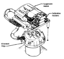
- a mechanical frame, called the navigation base (or navbase), to rigidly connect the optical devices and, in the LM, the rendezvous radar to the IMU
- the AGC software
Versions edit

The CM and LM used the same computer, inertial platform and resolvers. The main difference was the optical unit. The navbase was different for each spacecraft as well, reflecting the differing mounting geometries. The LM's rendezvous radar was also connected to its navbase.
There were two versions of PGNCS—Block I and Block II—corresponding to the two generations of the CM. After the Apollo I fire, which occurred in a Block I CM, NASA decided that no further crewed missions would use Block I, though uncrewed missions did. Major differences between Block I and Block II PGNCS included replacing electromechanical resolvers with an all electronic design and replacing the Block I navbase, which was machined from beryllium, with a frame built out of aluminum tubing filled with polyurethane foam. The Block II navbases were lighter, cheaper, and just as rigid.
Another major difference between Block I and Block II was repairability. An original goal for the Apollo program was for the astronauts to be able to make repairs to the electronics. Accordingly, the Block 1 PNGCS was designed with many identical modules that could be replaced with spares, if necessary, in flight. However high humidity conditions inside the crew compartments and accidents in handling body fluids during the Gemini 7 mission made having unsealed electrical connections undesirable. The repairability goal was eliminated in Block II and all units and electrical connections were sealed.[1] The fatal Apollo 1 fire reinforced this concern.
Inertial measurement unit edit

The IMU was gimbaled on three axes. The innermost part, the stable member (SM), was a 6-inch beryllium cube, with three gyroscopes and three accelerometers mounted in it. Feedback loops used signals from the gyroscopes by way of the resolvers to control motors at each axis. This servo system kept the stable member fixed with respect to inertial space. Signals from the accelerometers were then integrated to keep track of the spacecraft's velocity and position. The IMU was derived from the guidance system developed by Draper for the Polaris missile.
Inertial guidance systems are not perfect and Apollo system drifted about one milliradian per hour. Thus it was necessary to realign the inertial platform periodically by sighting on stars.
Optical units edit


The CM optical unit had a precision sextant (SXT) fixed to the IMU frame that could measure angles between stars and Earth or Moon landmarks or the horizon. It had two lines of sight, 28× magnification and a 1.8° field of view. The optical unit also included a low-magnification wide field of view (60°) scanning telescope (SCT) for star sightings. The optical unit could be used to determine CM position and orientation in space.

The LM instead had an alignment optical telescope (AOT), essentially a periscope. The outer element of the AOT was a sun-shielded prism that could be rotated to one of six fixed positions relative to the LM, in order to cover a large portion of the lunar sky. Each position had a 60° field of view. When rotated, the AOT's position was readable by the AGC; by pointing the reticule at two different stars, the computer could determine the craft's orientation.[2]
Apollo 11 Command Module Pilot Michael Collins noted that the visibility through the optics was sub-standard, and it was difficult to see through in certain lighting conditions.
The sun shade was added late in the program, in 1967, after tests and modeling determined that the astronauts might not be able to see stars on the lunar surface due to direct sun light or light scattered by near-by parts of the LM impinging on the outside prism. Adding the sun shade also allowed increasing the number of view positions from three to six.[1]: p. 41 ff

Software edit
The onboard guidance software used a Kalman filter to merge new data with past position measurements to produce an optimal position estimate for the spacecraft. The key information was a coordinate transformation between the IMU stable member and the reference coordinate system. In the argot of the Apollo program this matrix was known as REFSMMAT (for "Reference to Stable Member Matrix"). There were two reference coordinate systems used, depending on the phase of the mission: One centered on Earth and one centered on the Moon.
edit
Despite the word "primary" in its name, PGNCS data was not the main source of navigation information. Tracking data from NASA's Deep Space Network was processed by computers at Mission Control, using least squares algorithms. The position and velocity estimates that resulted were more accurate than those produced by PGNCS. As a result, the astronauts were periodically given state vector updates to enter into the AGC, based on ground data. PGNCS was still essential to maintain spacecraft orientation, to control rockets during maneuvering burns, including lunar landing and take off, and as the prime source of navigation data during planned and unexpected communications outages. PGNCS also provided a check on ground data.
The lunar module had a third means of navigation, the abort guidance system (AGS), built by TRW. This was to be used in the event of failure of PGNCS. The AGS could be used to take off from the Moon, and to rendezvous with the Command Module, but not for landing. During Apollo 13, after the most critical burn near the Moon, the AGS was used in place of PGNCS because it required less electrical power and cooling water.
Apollo 11 edit
During the Apollo 11 mission, two PGNCS alarms (1201 "No VAC areas available" and 1202 "Executive alarm, no core sets") were relayed to mission control as the first lunar landing was being attempted on July 20, 1969. The computer system overload was caused by the simultaneous capture of landing radar data and rendezvous radar data. Support staff at Mission control concluded that the alarms could be safely ignored and the landing succeeded.[3][4]
See also edit
- Saturn V instrument unit − guidance system used by the Apollo launch vehicles
References edit
- ^ a b Holley, M. D. (May 1976). "Apollo Experience Report--Guidance And Control Systems: Primary Guidance Navigation And Control System Development, NASA TN D-8287" (PDF). Lyndon B. Johnson Space Center, United States. National Aeronautics and Space Administration.
- ^ The Apollo Lunar Module Alignment Optical Telescope, Apollo Lunar Surface Journal
- ^ Eyles, Don (2004-02-06), Tales from the Lunar Module Guidance Computer, retrieved 2017-10-01
- ^ "Apollo 11 Lunar Surface Journal: Program Alarms". www.hq.nasa.gov. Retrieved 2017-04-16.