


Summary
The Atari joystick port is a computer port used to connect various gaming controllers to game console and home computer systems in the 1970s to the 1990s. It was originally introduced on the Atari 2600 in 1977 and then used on the Atari 400 and 800 in 1979. It went cross-platform with the VIC-20 in 1981, and was then used on many following machines from both companies, as well as a growing list of 3rd party machines like the MSX platform and various Sega consoles.
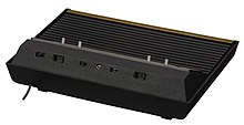
 Atari 2600 joystick port | |||
| Type | Human input device interface | ||
|---|---|---|---|
| Production history | |||
| Designed | 1977 | ||
| General specifications | |||
| Hot pluggable | yes | ||
| External | yes | ||
| Pins | 9 | ||
| Connector | D-subminiature | ||
| Pinout | |||
 | |||
| Console-side joystick port seen from the front. | |||
| Pin 1 | Up | ||
| Pin 2 | Down | ||
| Pin 3 | Left | ||
| Pin 4 | Right | ||
| Pin 5 | Paddle B | ||
| Pin 6 | Trigger | ||
| Pin 7 | +5 volts power | ||
| Pin 8 | Ground | ||
| Pin 9 | Paddle A | ||
The port, based on the inexpensive 9-pin D-connector, became a de facto standard through the 1980s and into the 1990s, supported by a wide variety of joysticks and other devices, most commonly paddle controllers, light pens and computer mice. The standard was so engrained that it led to devices like the Kempston Interface that allowed Atari joysticks to be used on the ZX Spectrum. The port was also used for all sorts of non-gaming roles, including the AtariLab interface, modems, numeric keypads, and even a video expansion card.
By the mid-1990s, the last home computer and game console models using Atari ports – often for both joystick and mouse – were discontinued. IBM PC-compatible computers, which did not have Atari joystick ports, became dominant in the home computer market, and console manufacturers such as Sega switched to other types of ports.
History edit

The Atari Video Computer System (later the 2600) developed out of an effort to address problems Atari found when releasing their first home video game console, Pong. Although successful, Pong was an expensive system to design, and was dedicated solely to one game. It would be much more practical to have a machine that could run multiple games. The list of games it would need to support included Pong variations, and Tank.[1] It was the desire to run these two games that led to the need for some sort of flexible input system; Pong used analog paddle controllers, while Tank used dual digital (on/off) joysticks. Arcade games of the era generally used paddles, joysticks or a unique sort of steering wheel controller that was spun, entirely unlike a real car.[1]
Development of the 2600 was strictly a paper project until September 1975, when the MOS Technology 6502 processor was released. The 6502 offered the right combinations of features, performance and price that made a console using ROM cartridges for program storage practical for the first time. Now that such a machine seemed like a real possibility, the design team at Cyan Engineering began serious development.[2]
As part of this effort, Joe Decuir began development of an I/O system based primarily on the MOS Technology 6532, which included 8-bit I/O ports as well as the hardware needed to control memory refresh and similar housekeeping tasks. Ultimately, the design used five of the I/O ports (pins) to control the various front-panel switches, and four each for the two controllers. Additionally, the TIA, whose primary task was sound and video, was used to handle timing-based controllers like paddles and light pens. The physical interface was the 9-pin D-sub connector, which was already relatively common for reduced pin-count serial ports on the Apple II and S-100 bus machines. Each of the pins in the connector went directly to the appropriate pin on the associated chip.[3]
The 2600 was released in 1977, shipping with both the paddle controllers and a single joystick. The port allowed the 2600 to more easily support a wider variety of games, not just specific games but entire genres. Most game consoles before the Atari had paddle controllers, even detachable ones in the case of the Fairchild Channel F and Magnavox Odyssey. But the joystick was new, and quickly garnered praise as it allowed direct input into a number of games that would otherwise be difficult to control using a paddle.[4] The joystick has been called "the pinnacle of home entertainment controllers in its day".[5]
After the release of the 2600, the Cyan team immediately turned to the development of its replacement,[note 1] aiming for the 1979 time frame.[6] As the "standard" was already set on the 2600, the new machines naturally used the same controller interface, although the details of the systems used to read it changed. As 1979 approached the home computer market emerged, and Atari repositioned the new system as the 400 and 800, the first members of the Atari 8-bit family. This meant the standard now crossed the line between consoles and computers.[7]
The port design was extremely flexible, and over time saw not only a wide variety of input devices, but output as well. Included among the non-controller devices was the AtariLab system that allowed users to plug in various laboratory devices like digital thermometers,[8] the 300 baud MPP-1000C modem,[9] and even Atari's own 80-column adaptor for the 8-bit series, the XEP80.[10] It was widely used in the home-brew market as a lightweight input device, and articles on how to build various adapters were common.[11]
Commodore included an Atari joystick port with the VIC-20 computer.[12] Atari had patents on the joystick and won an injunction against Commodore, which produced an almost identical "imitation" joystick for the VIC-20,[13] but held no patents on the port itself. By the time Commodore began development of the VIC-20 millions of controllers compatible with the port were in the market.
The Atari joystick port rapidly proliferated across the industry. Hundreds of new devices using the system cropped up over time, including trackballs and other advanced inputs.[14][15][16] The standard became so widely used that almost every 8-bit machine released after 1982 used it, and adapters were available for those that did not, like the Apple II and ZX Spectrum.[17][18][19] One TI-99/4A reseller reported that its best-selling product was the Atari joystick adapter.[20] The port moved to 16/32-bit machines like the Atari ST and Amiga as well.[21]
The introduction of the Nintendo Entertainment System was the first widespread example of a gaming system in that era that did not use the Atari design, its D-pad having been designed specifically to be less bulky.[22] As newer consoles were released into the newly invigorated market, new port designs were introduced for every different model. Meanwhile, the IBM PC had introduced the 15-pin game port that was designed primarily for analog inputs, but use remained rare until the introduction of popular flight simulators.[23]
By the mid-1990s, the Atari standard was becoming obsolete when home computers like Atari ST and Amiga exited markets along with Sega Genesis game console. With the Atari STE Atari introduced the enhanced joystick port (15 pin dsub) alongside the 2 joystick ports from Atari ST, and when the Jaguar was released, they only used the enhanced joystick port.[24] Nevertheless, it was so popular during its run that it remains a common staple in video game iconography to this day,[25] and is commonly referred to as the symbol of the 1980s video game system and system design.[26] There have also been numerous systems to allow the ports to be adapted to Universal Serial Bus, and even entirely new Atari-like joystick designs using USB.[27]
Description edit
The Atari joystick port used a 9-pin male socket in the host system, and female connectors on the devices. Classic Atari peripherals used a teardrop shaped rounded plug that was easy to grip to make it easier to plug in. Almost all compatible devices used similar physical layouts, often to the point of copying the plug design outright.
In the Atari consoles and 8-bit computers, reading the stick inputs was handled by a polling process that set values in various 8-bit registers. In the 8-bit machines, for instance, the pins in the port were connected to custom I/O hardware. The instantaneous values were polled 30 times a second during the vertical blank interrupt (VBI) when the operating system (OS) handled a number of housekeeping tasks. Depending on settings in other registers, the inputs on the pins were interpreted in a number of ways and then the output data was placed in a number of RAM registers. Atari referred to this copying from hardware to the RAM as "shadowing".[28]
Joysticks edit

Atari joysticks included four internal switches to encode direction, and a fifth for the trigger button. Each of these led directly to a pin in the port, and from there to an input on one of the I/O chips. The OS would read these inputs on each VBI, and then copy their status into the shadow registers, with the lower-numbered ports in the least significant bits. For instance, if stick 0 was being pushed up and to the right, the PORTA register would have bits 0 and 3 set, or decimal value 9. The status of each of the joystick's trigger buttons was instead placed in four separate registers, whose zero-bit would be set to 1 if the trigger was pushed.[29]
Driving controllers edit
Driving games of the 1980s were generally top-down and used a unique controller that would cause the car to turn at a fixed rate to one side or the other or go in a straight line (Atari's Night Driver is a notable exception). These games were controlled not by a wheel that pointed left or right like in a real car, but a wheel that sent left or right commands only if it was actively spinning in that direction. Players would spin the wheel rapidly to get the car to turn as fast as possible in the desired direction, and then brake the wheel with their hands to go straight again.[30]
Driving controllers were implemented on Atari consoles with a device that worked in the same fashion as the joysticks, pressing each directional switch in turn as it spun. Programs had to watch the sequence of bits in the shadow registers in order to tell if the controller was being spun to the right or left. The OS itself did not attempt to interpret this to provide "right" and "left" instructions for the programmer.[31]
Paddles edit
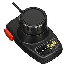
Paddles are analog devices normally used to control horizontal positioning of the player on the screen. On the Atari systems, the paddles were connected in pairs, allowing up to four people to play together on a two-port system.
The paddles worked by connecting the +5 V line through a potentiometer (pot) and then back into pins 5 and 9, one for each paddle in the pair. Those pins were connected to a capacitor, slowly charging it at a rate set by the position of the pot. When the voltage in the capacitor reached a threshold value, it caused an interrupt in the OS that copied the value of the color clock value from the video hardware. Normally this produced a value from 0 to 228 which was stored as an 8-bit value in the appropriate POT shadow register.[32]
One advantage to this system was the color clock values provided by the paddle controllers were the same numbers that controlled the horizontal location of sprites, meaning that the programmer could simply copy the value of the pot shadow register into the sprite's horizontal position register and it would appear at the appropriate location on-screen.[32]
Keyboard controllers edit
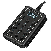
Keyboard controllers were used in the Atari systems as auxiliary inputs, for numeric keypads on the 8-bit machines and special purpose controllers on the 2600, like the Star Raiders port. They were based on a 4-by-3 matrix for a total of 12 possible keys. For any keypress, the row was encoded by setting one of four bits in the joystick shadow register, PORTA or PORTB, while the column set a bit on one of the trigger registers. The programmer then had to read both to determine which key was pressed; there was no firmware to map this onto key codes (which the 2600 lacked anyway).[33]
Light pen edit

Light pens were directly supported as well. In this case, a phototransistor in the light pen was connected to the trigger line of the port. If placed in light pen mode, whenever the trigger was seen to go low, the OS would copy the color clock value into the PENH register to record the horizontal position, and the VCOUNT register of the video hardware into the PENV register. The result was a set of two eight-bit values directly encoding the position of the pen in X and Y using the same coordinates as the video hardware. A sprite can then be set to those coordinates and will appear under the light pen. As the timers were not very accurate, the positions had to be averaged over several screens to produce a usable value.[34]
Graphics tablets edit
Graphics tablets were handled using the same hardware as the paddle controllers, encoding the X axis as the output of one paddle and the Y axis as the other. There were three buttons, one on the stylus and one on either upper corner of the pad. The stylus button was connected to the up direction of the joystick port, while the left and right buttons on the tablet itself were connected to two of the trigger inputs.[35]
Output edit
Because the pins of the joystick were wired directly to the input/output controllers on the motherboard, it was possible to program them to output to the port, rather than input. This capability was used in the Atari XEP80 80-column card, which used pin 1 as an output pin, and pin 2 as an input. A device driver used these pins to implement a bidirectional serial port, which worked in joystick port 1 or 2.[36] Similar drivers were used by other devices, like modems, which avoided the need to use the more expensive Atari SIO system.[37]
Other platforms edit
Fully compatible systems edit
The VIC-20 has one Control Port, and the Commodore 64 had two ports, each a complete implementation of the Atari standard. They differed from the Atari systems primarily in the hardware used to decode the inputs.
The digital pins on the Commodore 64's control ports were read by a MOS Technology CIA chip, and the analog paddle inputs in fashion similar to the Atari by the MOS Technology SID sound chip in conjunction with a timer. [38] There was only one set of two inputs for this purpose in the SID, so another register controlled which of the two ports was connected to the SID at any given instant. Light pens could only be used in Control Port 1 and worked in a similar way to the Atari, but was based on a faster clock so the horizontal axis read from 0 to 511. The accuracy was the same as the Atari however, as the values were rounded off to even values only.[39]
The same port pins on the CIA #1 were also used for handling the keyboard and other housekeeping tasks, which led to some problems. For instance, the left direction switch of Control Port 1 was wired to the same input as the CTRL key on the keyboard, and when it was used it would cause scrolling in BASIC programs to slow down. Due to the way keyboard scanning was handled, holding down the trigger would cause random characters to be generated. As a result, many C64 games required the joystick to be plugged into Control Port 2.[40][41]
On the Atari ST, the two ports were normally configured with Port 0 set to mouse mode and Port 1 to joystick. In joystick mode they operated largely identically to the earlier machines, but in mouse mode the system watched the ports for discrete inputs on the various directional pins, or "events". The mouse sensor generated 200 events for every inch of movement, and the system could track these fast enough to handle movements of up to 10 inches per second.[42] Handling the ports, the keyboard and a real-time clock was a dedicated Intelligent Keyboard (ikbd) controller.[43] The ST implementation of the joystick port lacked analog input, the following STE model introduced an enhanced joystick port which used a 15-pin dsub that had analog support.
The Commodore Amiga had a complete two-port implementation known as gameports. Unlike earlier systems that had to be interpreted by examining bits in registers, the Amiga's OS had a number of drivers and libraries that made interaction simple. This included handlers for five types of input devices, include mice, joysticks, light pens and "proportional controllers" as a catch-all for analog inputs like paddles and analog joysticks. They also had settings for how and when the OS would report changes. For instance, the programmer could set the drivers to only report when the mouse had moved at least 10 events, thus lowering how often they had to deal with mouse movement.[44]
Semi-compatible systems edit
The TI-99/4A home computer series used a 9-pin connector that was physically identical to the Atari version, as well as being similar in terms of the devices and the way they worked. However, the port's pins were re-arranged and it used the separate grounds to select which joystick to read, so it was not directly compatible. Converters allowing Atari-standard devices to be plugged in were both simple and very common.[45] The manufacturer and most makers of adapters included diodes on all lines of each joystick except the grounds to prevent false key presses.[46][47]
The ColecoVision game console extended the 2600 controller with two (or four) triggers and a 12 key pad. The ColecoVision also supported driving controllers and trackballs. Many ColecoVision games can be played with an Atari-compatible controller, if a Coleco controller is plugged into the second port and used to select the game.
The Atari 7800 game console extended the 2600 controller with a second trigger. 7800 games not requiring two triggers can be played with classic controllers.
MSX home computers used a slightly modified version of the port, replacing one of the analog inputs with a second trigger, and the other with a strobe pin. Under normal operation, any Atari style joystick could be used, although it would lack the second trigger button. The strobe pin was used to support mouse input. Electrically, a mouse generates what is essentially a random stream of pulses as it moves. On systems like the ST and Amiga, custom hardware was used to carefully track these in order for the motion to be smoothly followed, as the CPU might become too busy with other tasks to follow the rapid interrupts. Less powerful 8-bit designs did not have the performance to smoothly track a mouse without additional hardware, and the MSX designs, based on off-the-shelf hardware, lacked this ability. Instead, the tracking hardware was moved into the mouse. The mice held two 8-bit values tracking the movement in X and Y since the last time they had been polled. To read the values out, the strobe pin was pulled high four times. With each pulse, a nibble of the two bytes was output on the four directional pins in serial fashion. The strobe pulse also reset the value to zero, starting the polling process over again. MSX mice were expensive, and this led to adaptors for PS/2 style mice, which operated along similar principles.[48]
Sega Master System and Genesis game console controllers are backward-compatible and can be used with the Atari 2600.
Not all Magnavox Odyssey 2 systems had removable controllers. For the models that do, a simple adapter to rearrange the pins is all that is required.[49]
Some Amstrad PCs, that were otherwise IBM PC compatible, had Atari-compatible digital gameports rather than the PC analog standard. Software such as Elite and GEM had support for the Amstrad digital gameport. Otherwise, the joystick directionals were mapped to keys on the keyboard.[50]
Systems using adaptors edit
The Apple II also had a joystick port using a 9-pin D-sub, but it was a very different system that connected two analog joysticks to a single port. These were not very suitable for directional games, and adapters for Atari port devices were common, both commercial ones like the Sirius Joyport, as well as many home-brew systems. Unlike the ports used on the Commodore systems, most of the homebrew systems only adapted the joystick, and generally did not include the other inputs. These adapters did not allow the analog inputs of paddles to be used, in spite of the port already handling these inputs directly meaning all that was needed was a mechanical adapter.[51][52]
The ZX Spectrum prior to the Spectrum +2 had no built-in controller port, which led to a profusion of different inputs. Atari port adapters were common, and several devices emerged including the Kempston Interface and ZX Interface 2 that were incompatible with each other. The Interface 2 turned joystick presses into keyboard presses,[53] and thus could not generate the analog signals of the paddles. The later Amstrad-built Spectrum models - the +2, +2A, and +3 - included two built-in joystick ports, however the pinout of the connectors was non-standard. One-button Atari joysticks can be used with a simple wiring adaptor to convert the ports to the standard pinout.
The BBC Micro had a relatively complex port system which was based on a 15-pin D-connector that supported two analog joysticks like the ones on the Apple II. These ran to dedicated analog-to-digital circuitry, which made them excellent for the sort of interfacing tasks seen in (for instance) AtariLab. However, the popularity of the Atari port was such that adapters were also available for this system, varying widely in the number and types of control devices they supported.[54]
Chart of compatible systems edit
| Pin | Atari 800 Atari VCS [55] |
Atari 7800 [a][56] |
Atari ST |
VIC-20 C64 C64GS C128 [b][57] |
Amiga [58] | CD32 [c] |
Amstrad CPC [59] |
Amstrad GX4000 |
MSX [60] | Master System [d][61] |
Mega Drive (Genesis) [62] |
Sinclair [e][63] |
Tomy Tutor/Pyuuta [f] |
TI-99/4A [f] |
Odyssey2 |
|---|---|---|---|---|---|---|---|---|---|---|---|---|---|---|---|
| 1 | Up | Up | Up | Up | Up | Up | Up | Up | Up | Up | Up | unused | GND P1 | unused | GND |
| 2 | Down | Down | Down | Down | Down | Down | Down | Down | Down | Down | Down | common | GND P2 | P2 GND | Button 1 |
| 3 | Left | Left | Left | Left | Left | Left | Left | Left | Left | Left | 1Y (-, Left) | unused | Button 1 | Up | Left |
| 4 | Right | Right | Right | Right | Right | Right | Right | Right | Right | Right | 2Y (-, Right) | Button 1 | Button 2 | Button 1 | Down |
| 5 | Paddle B | Button Right | unused | Button 3 (POTY) | Button 3 (POTY) | Shift Load OUT | Button 3 | not connected | VCC | VCC (+5 V) | VCC (+5 V) | Up | Down | Left | Right |
| 6 | Button | Button | Button 1 | Button 1 | Button 1 | Fire, Clock OUT | Button 2 | Button 1 | Button 1 | TL (1, trigger) | TL (A, B) | Right | Left | unused | Up |
| 7 | VCC (+5 V) | VCC (+5 V) | VCC (+5 V) | VCC (+5 V) | VCC (+5 V) | VCC (+5 V) | Button 1 | Button 2 | Button 2 | TH (light sensor) | TH (Select OUT) | Left | Up | P1 GND | unused |
| 8 | GND | GND | GND | GND | GND | GND | GND (Row 9) [g] | GND | Strobe OUT | GND | GND | common | Right | Down | unused |
| 9 | Paddle A | Button Left | Button 2 (port 0 only) | Button 2 (POTX) | Button 2 (POTX) | Serial Data IN | GND (Row 6) [g] | not connected | GND | TR (2) | TR (Start, C) | Down | unused | Right | unused |
- ^ Atari 7800 buttons require special wiring.
- ^ For the second button/right mouse button the POT X line is used (and for 3rd button/middle mouse button POT Y) which, different to the other lines, must be pulled to VCC via the button.
- ^ The CD32 supports "game pad mode" and uses pin 5 to switch to it; it is pulled to active high by the CD32. Actual CD32 controllers have active components. Regular "Atari" joysticks will work at the CD32, but CD32 controllers will not work with e.g. a C-64.
- ^ The "Sega" controllers cannot be converted into "Atari" joysticks simply by rewiring them. Unlike regular "Atari" joysticks, they contain pull-up resistors for each signal line (which might interfere with scanning the keyboard on C64) and some controllers may contain active circuits and will not work without the VCC. The Mega Drive controllers use an active circuit.
- ^ Refers to the ports built into the ZX Spectrum +2, +2A, and +3 models. Other Spectrum joystick interfaces typically match the 1-button "Atari" pinout.
- ^ a b The TI-99/4A and Tutor/Pyuuta controllers were typically two controllers plugged into one port. The pinouts need 1N914 diodes with the Cathode pointed to the controller side to prevent false key presses.
- ^ a b The respective GND lines are pulled low to select the respective "row". Regular joysticks use row 9.
Notes edit
- ^ Cyan had been purchased outright by Atari in 1977, but remained independent and operated out of their Grass Valley, California offices for a time.
References edit
Citations edit
- ^ a b Decuir 2015, p. 60.
- ^ Decuir 2015, p. 61.
- ^ Decuir 2015, p. 64.
- ^ Montfort, Nick; Bogost, Ian (2014). Stella and Combat: A BIT of Racing the Beam. MIT Press. p. 22. ISBN 9780262316446.
- ^ Rollings, Andrew; Adams, Ernest (2003). Andrew Rollings and Ernest Adams on Game Design. New Riders. p. 167. ISBN 9781592730018.
- ^ Decuir 2015, p. 66.
- ^ Edwards, Benj (4 November 2009). "Inside the Atari 800". PCWorld.
- ^ Jackson, Charles (October 1984). "AtariLab". Antic.
- ^ "Replace your interface with a loaded modem". InfoWorld: 95. 7 May 1984.
- ^ Jackson, Charles (July 1987). "Miracle Box From Atari". Antic.
- ^ Dubin, Marshall (1983). "Interfacing Your Atari". In Small, David (ed.). The Creative Atari.
- ^ Thornburg, David (April 1981). "The Commodore VIC-20: A First Look". Compute!: 26.
- ^ "Atari wins joystick battle". InfoWorld: 5. 29 November 1982.
- ^ Mace, Scott (14 February 1983). "Advanced game controllers debut at consumer show". InfoWorld: 28–29.
- ^ Boaz, Joaquin (8 August 1983). "Good news, bad news - new games, joystick revealed". InfoWorld: 22–24.
- ^ Fernandez, Adelbert (May 1986). "DE RE JOYSTICK: Programming & Repairing The First User Friendly Computer Interface". Antic.
- ^ Riley, Tom; Riley, Kelda (1983). The Computer Controller Cookbook. Creative Computing Press. p. Chapter 9.
- ^ Malcolm, Bruce (1983). "The Atari Connection". Nibble: 162.
- ^ Mace, Scott (11 April 1983). "Trackballs fail to navigate rapidly in maze games". InfoWorld: 26, 27.
- ^ Mace, Scott (1984-04-09). "Atarisoft vs. Commodore". InfoWorld. p. 50. Retrieved 4 February 2015.
- ^ Commodore 1987, Appendix A, p. A-10.
- ^ Kent, Steven (2001). The Ultimate History of Video Games: The Story Behind the Craze that Touched our Lives and Changed the World. Prima Publishing. p. 279. ISBN 9780307560872.
- ^ Calvert, J. B. (18 August 2002). "The Game Control Adapter". A Review of Electronics.
- ^ The Atari Enhanced Joystick Ports (Technical report). 24 September 1996.
- ^ Wolf, Mark (2012). Before the Crash: Early Video Game History. Wayne State University Press. p. 67. ISBN 978-0814337226.
- ^ Lidwell, William; Manacsa, Gerry (2011). Deconstructing Product Design. Lockport Publishers. p. 97. ISBN 9781592537396.
- ^ Sorrel, Charlie (29 January 2010). "The Classic Wrist-Busting Atari Joystick is Back". Wired.
- ^ Atari 1982, p. II.30, III.19.
- ^ Atari 1982, pp. II.30–II.31.
- ^ Indy 800 Service Manual (PDF). 1977.
- ^ Atari Hardware Manual (PDF). Atari. 1983.
- ^ a b Atari 1982, pp. II.31.
- ^ Atari 1982, p. II.31, III.23.
- ^ Atari 1982, p. II.32.
- ^ Using Atari Touch Tablet with BASIC (PDF) (Technical report). Atari. 10 March 1984. p. Appendix II.
- ^ Atari XEP80 Interface Module Owner's Manual. Atari Corp. 1987.
- ^ Weber, John (July 1984). "MPP-1000C Modem". Antic.
- ^ Commodore 1982, p. 346.
- ^ Commodore 1982, p. 348.
- ^ "Control Port". C64 Wiki.
- ^ Tyborski, Michael (June 1983). "Joysticks For The Commodore 64". Compute!: 210.
- ^ Peel, Katherine (1986). The Concise Atari ST 68000 Programmer's Reference Guide (PDF). Glentop. pp. 1–18.
- ^ Intelligent Keyboard (ikdb) Protocol (Technical report). Atari. 26 February 1985.
- ^ Amiga Hardware Reference Manual. Commodore International. p. Chapter 8. Archived from the original on 2019-12-02. Retrieved 2015-12-12.
- ^ Cook, Gary (August 1983). "How To Build Your Own TI-99/4A Joystick Adapter". Compute!: 10.
- ^ Pearson, Glenn (1996-07-01). "Atari to TI Joystick Adapter". Mainbyte's Home of the Texas Instruments Computers. Retrieved 2021-04-03.
- ^ Kagan, Aubrey (2015-07-08). "Keyboard and display multiplexing — the traditional approach". embedded. Retrieved 2021-04-03.
- ^ Nunes, Giovanni. "Joystick connector". MSX Connectors and Cables.
- ^ grips03 (2016-12-04). "Using Atari joysticks on the Odyssey 2". atariage.com. Retrieved 2021-04-03.
{{cite web}}: CS1 maint: numeric names: authors list (link) - ^ Nerdly Pleasures (2016-04-11). "The Amstrad PC-1512 : The Affordable IBM PC Compatible for Europe". nerdlypleasures.blogspot.com. Retrieved 2018-03-14.
- ^ Woita, Steve (2007), Classic Gaming Expo - Steve Woita, retrieved 2007-03-26
- ^ Ahl, David H.; Rost, Randi J. (1983), "Blisters And Frustration: Joysticks, Paddles, Buttons and Game Port Extenders for Apple, Atari and VIC", Creative Computing Video & Arcade Games, 1 (1): 106ff
- ^ Paul Farrow. "ZX Interface 2 - Custom ROM Cartridges". Fruitcake.plus.com. Retrieved 2011-05-15.
- ^ Connecting Joysticks to the BBC Micro (PDF) (Technical report). 9 July 1992.
- ^ iComp GmbH (2015-06-03). "DE-9 Joystick". Individual Computers. Retrieved 2021-07-05.
- ^ iComp GmbH (2015-06-03). "DE-9 Joystick". Individual Computers. Retrieved 2021-07-05.
- ^ iComp GmbH (2015-06-03). "DE-9 Joystick". Individual Computers. Retrieved 2021-07-05.
- ^ iComp GmbH (2015-06-03). "DE-9 Joystick". Individual Computers. Retrieved 2021-07-05.
- ^ iComp GmbH (2015-06-03). "DE-9 Joystick". Individual Computers. Retrieved 2021-07-05.
- ^ iComp GmbH (2015-06-03). "DE-9 Joystick". Individual Computers. Retrieved 2021-07-05.
- ^ iComp GmbH (2015-06-03). "DE-9 Joystick". Individual Computers. Retrieved 2021-07-05.
- ^ iComp GmbH (2015-06-03). "DE-9 Joystick". Individual Computers. Retrieved 2021-07-05.
- ^ iComp GmbH (2015-06-03). "DE-9 Joystick". Individual Computers. Retrieved 2021-07-05.
Bibliography edit
- Decuir, Joe (July 2015). "Atari Video Computer System: Bring Entertainment Stories Home". IEEE Consumer Electronics Magazine: 59–66.
- Introduction to the Amiga 2000. Commodore Business Machines. 1987.
- Atari Hardware Manual (PDF). Atari. 1982.
- Commodore 64 Programmers Reference Guide. Commodore Business Machines. 1982.