
-
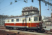 The Swiss Re 4/4I, built to negotiate curves at higher speeds, built in 1946 and weighing only 57 tons.
 -
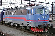
 The BLS Re 4/4, an early high performance Bo-Bo locomotive. Built from 1964 onwards, its 4980 kW is still significant for today's standards.
 -
 The Bombardier TRAXX MS2, a multiple system multi-purpose locomotive built for the European railways. Significant numbers of the TRAXX family have been built for most European railways.
 -
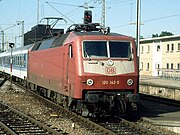 The DB Class 120, the first mass produced locomotive to use electronically controlled asynchronous three-phase motors to allow both high speed and high tractive effort.
 -
![The ÖBB 1216 050, the fastest electric locomotive ever built as of August 2012[update]. It is a Siemens ES64U4, a member of the EuroSprinter family.](//upload.wikimedia.org/wikipedia/commons/thumb/c/ce/ES64U4_OEBB_1216_050_Hersbruck_30062007.JPG/180px-ES64U4_OEBB_1216_050_Hersbruck_30062007.JPG) The ÖBB 1216 050, the fastest electric locomotive ever built as of August 2012[update]. It is a Siemens ES64U4, a member of the EuroSprinter family.
The ÖBB 1216 050, the fastest electric locomotive ever built as of August 2012[update]. It is a Siemens ES64U4, a member of the EuroSprinter family. -

KNOWPIA
WELCOME TO KNOWPIA
Bo-Bo 
Summary
B-B and Bo-Bo are the Association of American Railroads (AAR) and British classifications of wheel arrangement for railway locomotives with four axles in two individual bogies. They are equivalent to the B′B′ and Bo′Bo′ classifications in the UIC system. The arrangement of two, two-axled, bogies is a common wheel arrangement for modern electric and diesel locomotives.
Bo-Bo edit
Bo-Bo is the UIC[citation needed] indication of a wheel arrangement for railway vehicles with four axles in two individual bogies, all driven by their own traction motors. It is a common wheel arrangement for modern electric and diesel-electric locomotives, as well as power cars in electric multiple units.
Most early electric locomotives shared commonalities with the steam engines of their time. These features included side rods and frame mounted driving axles with leading and trailing axles. The long rigid wheelbase and the leading and trailing axles reduced cornering stability and increased weight.
The Bo-Bo configuration allowed for higher cornering speeds due to the smaller rigid wheelbase. Furthermore, it allowed better adhesion because all the wheels were now powered. Due to the absence of frame mounted wheels no leading or trailing axles were necessary to aid cornering, reducing weight and maintenance requirements.
Due to the advent of modern motors and electronics more power can be brought to the rail with only a few axles. Modern electric locomotives can deliver up to 6400 kW on only four axles. For very heavy loads, especially in transportation of bulk goods, a single unit with this wheel arrangement tends to have too little adhesive weight to accelerate the train sufficiently fast without wheelslip.
Bo-1-Bo edit
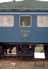
Eighteen of the Japanese 3 ft 6 in (1,067 mm) narrow-gauge Bo-Bo electric JNR Class ED61 were rebuilt in the late 1970s to form the Class ED62.[1] An additional carrying axle was added between the bogies to give a B-1-B (AAR) or Bo′1Bo′ (UIC) arrangement. The intention was to give a lighter axle loading for the Iida Line.
Bo-2-Bo edit

Another rare arrangement was the Bo-2-Bo used for two 3 ft 6 in (1,067 mm) gauge Japanese diesel-electric classes, the ED76 and ED78. These used flexicoil outer bogies which permitted the bogies some lateral movement, as well as swivelling.
Bo′Bo′+Bo′Bo′ edit

These are a pair of Bo′Bo′ locomotives semi-permanently coupled as a single unit. They are each constructed with a single cab, giving a cab at each end.
This layout includes the Alstom Prima II, one of the most powerful electric locomotives in production (9 MW (12,000 hp)). Versions include the China Railways HXD2 and the Indian WAG-12.

B′B′ edit


The B′B′ or B-B arrangement is similar, but usually applies to diesel-hydraulic locomotives rather than diesel-electrics. The axles on each bogie are coupled together mechanically, rather than being driven by individual traction motors. Diesel-hydraulics have their engine mounted on the main frame of the locomotive, together with a hydraulic transmission. Power is then transmitted to the bogies by cardan shafts and a short driveshaft between axles.[2]
A common example of this is the German V200 design and its many international derivatives. The need to arrange the bogie suspension around the drive shafts led to an unusual bogie design with radius arms rather than hornblocks and so prominently visible wheels and rims.[3][4]

In some rare examples, such as the SNCF Class BB 71000 and the narrow-gauge ÖBB 2095, the bogie axles have been linked by coupling rods. Having only a single final-drive per bogie allows more room for the bogie pivots on this narrow-gauge design. With high power full-size locomotives, splitting the drive directly to two axles is preferred, as it only requires a less powerful final drive gearbox.
In AAR notation a Bo-Bo is regarded as a B-B because the AAR system does not take traction motors into consideration, only powered axles. An AAR-like notation is used in France too, making it hard to tell the B-B and Bo-Bo engines apart, both of which are common there.
1A-A1 (or A1-1A) edit

Railcars and multiple units use similar two-axle powered bogies and many of them use similar hydraulic or mechanical transmissions, rather than traction motors. However railcars are also lightweight and do not require all axles to be powered in order to gain adequate adhesion. They thus use a wheel arrangement of 1A-A1 (UIC: (1A)(A1) ) (or A1-1A (UIC: (A1)(1A) ) ) rather than B-B.[5] A common arrangement is for each power car to have two independent engines and transmissions, each driving a single axle of each bogie.
The difference between 1A-A1 and A1-1A is that 1A-A1 has the powered axles closest to the middle of the car, whilst A1-1A has the powered axles closest to the ends.
2-B edit
The 2'Bo' (AAR:2-B) arrangement has been used similarly, but rarely, for lightweight railcars that only needed two powered axles. Only one example is recorded, the diesel-electric four-car Rebel railcars of 1935.[6] Three powercars were built, with a 600 bhp engine and two traction motors on a single bogie. Half of the powercar was used as a baggage car, supported by a conventional coaching stock unpowered bogie.
Gallery edit


![The ÖBB 1216 050, the fastest electric locomotive ever built as of August 2012[update]. It is a Siemens ES64U4, a member of the EuroSprinter family.](http://upload.wikimedia.org/wikipedia/commons/thumb/c/ce/ES64U4_OEBB_1216_050_Hersbruck_30062007.JPG/180px-ES64U4_OEBB_1216_050_Hersbruck_30062007.JPG)

See also edit
References edit
Wikimedia Commons has media related to Bo′Bo′ locomotives.
- ^ Sasada, Masahiro. 国鉄&JR保存車大全2015–2016 [JNR & JR Preserved Rolling Stock Complete Guide 2015–2016] (in Japanese). Tokyo, Japan: Ikaros Publications. p. 121. ISBN 978-4863209282.
- ^ Bolton, William F. (2006) [1956]. The Railwayman's Diesel Manual (4th ed.). Ian Allan. pp. 132–133. ISBN 0-7110-3197-5.
- ^ Clough, David N. (2011). "8: A contrast in design". Hydraulic vs Electric: The battle for the BR diesel fleet. Ian Allan. p. 77. ISBN 978-0-7110-3550-8.
- ^ Lewis, J.K. (2006) [1977]. The Western's Hydraulics. Nottingham: Book Law Publications. p. 50. ISBN 1-901945-54-5.
- ^ Bolton, pp. 135–136.
- ^ James H. Lemly. "Chapter XI: Renewed efforts toward growth, 1934–38". The Gulf, Mobile and Ohio.