


Summary
A brake wear indicator is used to warn the operator of a vehicle that the brake pad is in need of replacement. The main area of use for this is on motor vehicles with more than three wheels. However brake wear indicators are also useful for brake pads in industrial applications, including wind turbines and cranes.[1][2]
This article refers to disc brakes as an example, but the principle is the same for other types of friction brakes.
Types of indicators edit
There are different types of wear indicators for brake pads:
- Ocular inspection: A cut is made in the pad material to the depth where it shall be replaced. Requires visual inspection of the pads.
- Mechanical:[3][4] A metal plate is designed to contact the brake disk causing a noise when the pad has worn down to the desired level.
- Electrical: A metal body is embedded in the pad material that comes in contact with the rotor when the desired wear level is reached. This will light an indicator in the instrument cluster.
- Position sensor:[5] A sensor that measures the position of the brake mechanics and indicates to the driver when the desired position has been achieved.
Of the alternatives above the first three are simple and cheap since their lifetime coincides with the service life of the brake pad. The last one is more expensive since the sensors needs to be designed to survive the designed service life of the vehicle. This means that the last alternative is usually only seen on heavy duty vehicles.
Detailed description edit
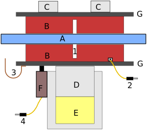
Pads B are mounted on carriers G. These are pushed against the rotor A by the piston D which is pushed by the brake fluid E. This induces wear on the brake pads. The rotor A also experiences some wear, but to a lesser extent than the brake pads. The modules C are joined to the cylinder that houses the piston D and acts as counter-force to the piston D.
Sufficient wear to validate a change of brake pads is considered when one of the following cases are applicable:
- The gap 1 is no longer visible or soon to be no longer visible.
- The embedded sensor in the brake pad 2 contacts the rotor and creates a connection to ground of the sensor.
- The metal plate 3 contacts the rotor and creates a noise. This wear clip should be positioned so that the rotor contacts the clip before it contacts the brake pad. The rotor should push against that clip, not drag it away from the brake pad. The pad that has this wear indicator should also be on the inside of the caliper, since the inside pad wears somewhat faster than the outside pad.
- The distance between the cylinder for piston D and the carrier G becomes too large, causing the sensor F to send a signal outside the permitted range through the sensor wire 4, or ground the sensor wire 4 if F is a contact.
F can either be an analog sensor, with an electronic threshold value set to signal an alarm when it has been reached, or an on/off switch, activated at a certain distance.
Under normal conditions, only one of the alternatives are used. Many front wheels on cars are equipped only with wear indicators.
Electric wear indicator edit

Electrical wear indicator is the alternatives 2 and 4 as displayed above.
Embedded in brake pads edit
The simplest form of this indicator is that the wire 2 is connected to the ground side of a bulb that will light up as soon as contact is made with the rotor. This can result in a flickering light for the indicator.
In some vehicles an electrical wear indicator of type 2 can be doubled and one sensor is on the 50% mark while the other is when the pad is worn out. The 50% mark is stored in the vehicle ECU and can be used by workshops to estimate if the remaining lifetime of the current pads is sufficient until the next regular maintenance or if the pads shall be changed before they have reached end of life in order to save the vehicle owner from an additional visit for changing just the brake pads.
Separate sensor edit
This sensor (4 in the picture) may be present on heavy duty vehicles and special vehicles as well as in industry applications where maintenance is expensive, which means that planning and proactive maintenance is important to be as cost effective as possible at each maintenance event.
A simpler variant of the separate sensor is that it is a simple contact with the same functionality as the sensor of type 2 in the picture. This may be validated in cases where the actual brake pad is in an environment that would destroy any electrical wiring, for instance high temperatures.
References edit
- ^ "Wind Turbine Brake Pads". Archived from the original on 2015-02-11. Retrieved 2015-02-11.
- ^ "Crane Brakes". Archived from the original on 2013-08-11. Retrieved 2013-10-04.
- ^ "How Stuff Works: How Disc Brakes Work".
- ^ "Installing Subaru 4-Pot Brakes". Archived from the original on 2013-10-05.
- ^ "Gill Sensors; Through-Hole Position Sensor".