


Summary
A circuit breaker is an electrical safety device designed to protect an electrical circuit from damage caused by current in excess of that which the equipment can safely carry (overcurrent). Its basic function is to interrupt current flow to protect equipment and to prevent fire. Unlike a fuse, which operates once and then must be replaced, a circuit breaker can be reset (either manually or automatically) to resume normal operation.
 A two-pole miniature circuit breaker | |
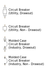
| Electronic symbol | |
|---|---|
 |


Circuit breakers are made in varying current ratings, from devices that protect low-current circuits or individual household appliances, to switchgear designed to protect high-voltage circuits feeding an entire city. Any device which protects against excessive current by automatically removing power from a faulty system, such as a circuit breaker or fuse, can be referred to as an over-current protection device (OCPD).
Origins edit
An early form of circuit breaker was described by Thomas Edison in an 1879 patent application, although his commercial power distribution system used fuses.[1] Its purpose was to protect lighting circuit wiring from accidental short circuits and overloads. A modern miniature circuit breaker similar to the ones now in use was patented by Brown, Boveri & Cie in 1924. Hugo Stotz, an engineer who had sold his company to Brown, Boveri & Cie, was credited as the inventor on German patent 458392.[2] Stotz's invention was the forerunner of the modern thermal-magnetic breaker commonly used in household load centers to this day.
Interconnection of multiple generator sources into an electrical grid required the development of circuit breakers with increasing voltage ratings and increased ability to safely interrupt the increasing short-circuit currents produced by networks. Simple air-break manual switches produced hazardous arcs when interrupting high-voltage circuits; these gave way to oil-enclosed contacts, and various forms using the directed flow of pressurized air, or pressurized oil, to cool and interrupt the arc. By 1935, the specially constructed circuit breakers used at the Boulder Dam project used eight series breaks and pressurized oil flow to interrupt faults of up to 2,500 MVA, in three AC cycles.[3]
Operation edit
All circuit breaker systems have common features in their operation, but details vary substantially depending on the voltage class, current rating and type of the circuit breaker.
The circuit breaker must first detect a fault condition. In small mains and low-voltage circuit breakers, this is usually done within the device itself. Typically, the heating or magnetic effects of electric current are employed. Circuit breakers for large currents or high voltages are usually arranged with protective relay pilot devices to sense a fault condition and to operate the opening mechanism. These typically require a separate power source, such as a battery, although some high-voltage circuit breakers are self-contained with current transformers, protective relays, and internal power sources.
Once a fault is detected, the circuit breaker contacts must open to interrupt the circuit; this is commonly done using mechanically stored energy contained within the breaker, such as a spring or compressed air to separate the contacts. A breaker may also use the higher current caused by the fault to separate the contacts, via thermal expansion or increased magnetic field. A small circuit breakers typically has a manual control lever to switch the circuit off or reset a tripped breaker, while a larger unit may use a solenoid to trip the mechanism, and an electric motor to restore energy to springs (which rapidly separate contacts when the breaker is tripped).
The circuit breaker contacts must carry the load current without excessive heating, and must also withstand the heat of the arc produced when interrupting (opening) the circuit. Contacts are made of copper or copper alloys, silver alloys and other highly conductive materials. Service life of the contacts is limited by the erosion of contact material due to arcing while interrupting the current. Miniature and molded-case circuit breakers are usually discarded when the contacts have worn, but power circuit breakers and high-voltage circuit breakers have replaceable contacts.
When a high current or voltage is interrupted, an arc is generated. The maximum length of the arc is generally proportional to the voltage while the intensity (or heat) is proportional to the current. This arc must be contained, cooled and extinguished in a controlled way, so that the gap between the contacts can again withstand the voltage in the circuit. Different circuit breakers use vacuum, air, insulating gas, or oil as the medium the arc forms in. Different techniques are used to extinguish the arc including:
- Lengthening or deflecting the arc
- Intensive cooling (in jet chambers)
- Division into partial arcs
- Zero-point quenching (contacts open at the moment in the AC waveform at which the current and potential are near zero, effectively breaking no load current at the time of opening. The zero-crossing occurs at twice the line frequency; i.e., 100 times per second for 50 Hz and 120 times per second for 60 Hz AC.)
- Connecting capacitors in parallel with contacts in DC circuits.
Finally, once the fault condition has been cleared, the contacts must again be closed to restore power to the interrupted circuit.
Arc interruption edit
Low-voltage miniature circuit breakers (MCB) use air alone to extinguish the arc. These circuit breakers contain so-called arc chutes, a stack of mutually insulated parallel metal plates that divide and cool the arc. By splitting the arc into smaller arcs the arc is cooled down while the arc voltage is increased and serves as an additional impedance that limits the current through the circuit breaker. The current-carrying parts near the contacts provide easy deflection of the arc into the arc chutes by a magnetic force of a current path, although magnetic blowout coils or permanent magnets could also deflect the arc into the arc chute (used on circuit breakers for higher ratings). The number of plates in the arc chute is dependent on the short-circuit rating and nominal voltage of the circuit breaker.
In larger ratings, oil circuit breakers rely upon vaporization of some of the oil to blast a jet of oil through the arc.[4]
Gas (usually sulfur hexafluoride) circuit breakers sometimes stretch the arc using a magnetic field, and then rely upon the dielectric strength of the sulfur hexafluoride (SF6) to quench the stretched arc.
Vacuum circuit breakers have minimal arcing (as there is nothing to ionize other than the contact material). The arc is quenched when it is stretched a very small amount (less than 3 mm (0.1 in)). Vacuum circuit breakers are frequently used in modern medium-voltage switch gear to 38000 volts.
Air circuit breakers may use compressed air to blow out the arc, or alternatively, the contacts are rapidly swung into a small sealed chamber, the escaping of the displaced air thus blowing out the arc.
Circuit breakers are usually able to terminate all current very quickly: typically the arc is extinguished between 30 ms and 150 ms after the mechanism has been tripped, depending upon age and construction of the device. The maximum current value and let-through energy determine the quality of the circuit breakers.
Short circuit edit
Circuit breakers are rated both by the normal current that they are expected to carry, and the maximum short-circuit current that they can safely interrupt. This latter figure is the ampere interrupting capacity (AIC) of the breaker.
Under short-circuit conditions, the calculated or measured maximum prospective short-circuit current may be many times the normal, rated current of the circuit. When electrical contacts open to interrupt a large current, there is a tendency for an arc to form between the opened contacts, which would allow the current to continue. This condition can create conductive ionized gases and molten or vaporized metal, which can cause the further continuation of the arc or create additional short circuits, potentially resulting in the explosion of the circuit breaker and the equipment that it is installed in. Therefore, circuit breakers incorporate various features to divide and extinguish the arcs.
The maximum short-circuit current that a breaker can interrupt is determined by testing. Application of a breaker in a circuit with a prospective short-circuit current higher than the breaker's interrupting capacity rating may result in failure of the breaker to safely interrupt a fault. In a worst-case scenario, a breaker may successfully interrupt a fault only to explode when reset.
Typical domestic panel circuit breakers are rated to interrupt 6 kA (6000 A) short-circuit current.
Miniature circuit breakers used to protect control circuits or small appliances may not have sufficient interrupting capacity to use at a panel board; these circuit breakers are called "supplemental circuit protectors" to distinguish them from distribution-type circuit breakers.
Standard current ratings edit

Circuit breakers are manufactured with standard ratings, using a system of preferred numbers to create a useful selection of ratings. A miniature circuit breaker has a fixed trip setting; changing the operating current value requires replacing the whole circuit breaker. Circuit breakers with higher ratings can have adjustable trip settings, allowing fewer standardized products to be used, adjusted to the applicable precise ratings when installed. For example, a circuit breaker with a 400 ampere frame size might have its over-current detection threshold set only 300 amperes where that rating is appropriate.
For low-voltage distribution circuit breakers an international standard, IEC 60898-1, defines rated current as the maximum current that a breaker is designed to carry continuously. The commonly available preferred values for rated current are 1 A, 2 A, 4 A, 6 A, 10 A, 13 A, 16 A, 20 A, 25 A, 32 A, 40 A, 50 A, 63 A, 80 A, 100 A,[5] and 125 A. The circuit breaker is labeled with the rated current in amperes prefixed by a letter, which indicates the instantaneous tripping current that causes the circuit breaker to trip without intentional time delay expressed in multiples of the rated current:
| Type | Instantaneous tripping current |
|---|---|
| B | 3–5 times rated current In, e.g. a nominally 10 A device will trip at 30–50 A |
| C | 5–10 times In |
| D | 10–20 times In |
| K | 8–12 times In
For the protection of loads that cause frequent short-duration (approximately 400 ms to 2 s) current peaks in normal operation |
| Z | 2–3 times In for durations on the order of tens of seconds.
For the protection of loads such as semiconductor devices or measuring circuits using current transformers. |
Circuit breakers are also rated by the maximum fault current that they can interrupt; this allows use of more economical devices on systems unlikely to develop the high short-circuit current found on, for example, a large commercial building distribution system.
In the United States, Underwriters Laboratories (UL) certifies equipment ratings, called Series Ratings (or "integrated equipment ratings") for circuit breaker equipment used for buildings. Power circuit breakers and medium- and high-voltage circuit breakers used for industrial or electric power systems are designed and tested to ANSI or IEEE standards in the C37 series. For example, standard C37.16 lists preferred frame size current ratings for power circuit breakers in the range of 600 to 5000 amperes. Trip current settings and time–current characteristics of these breakers are generally adjustable.
For medium- and high-voltage circuit breakers used in switchgear, substations and generating stations, relatively few standard frame sizes are generally manufactured. These circuit breakers are usually controlled by separate protective relay systems, offering adjustable tripping current and time settings as well as allowing for more complex protection schemes.
Types edit

Many classifications of circuit breakers can be made, based on their features such as voltage class, construction type, interrupting type, and structural features.
Low-voltage edit
Low-voltage (less than 1,000 VAC) types are common in domestic, commercial and industrial application, and include:
- Miniature circuit breaker (MCB)—rated current up to 125 A. Trip characteristics normally not adjustable. Thermal or thermal-magnetic operation. Breakers illustrated above are in this category.
- Molded Case Circuit Breaker (MCCB)—rated current up to 1,600 A. Thermal or thermal-magnetic operation. Trip current may be adjustable in higher-rated units.
- Low-voltage power circuit breakers can be mounted in multiple tiers in low-voltage switchboards or switchgear cabinets.
The characteristics of low-voltage circuit breakers are given by international standards such as IEC 947. These circuit breakers are often installed in draw-out enclosures that allow removal and interchange without dismantling the switchgear.
Large low-voltage molded-case and power circuit breakers may have electric motor operators so they can open and close under remote control. These may form part of an automatic transfer switch system for standby power.
Low-voltage circuit breakers are also made for direct-current (DC) applications, such as for subway lines. Direct current requires special breakers because the arc is continuous—unlike an AC arc, which tends to go out on each half cycle, a direct-current circuit breaker has a blow-out coil that generates a magnetic field that rapidly stretches the arc. Small circuit breakers are either installed directly in equipment or arranged in breaker panels.

The DIN-rail-mounted thermal-magnetic miniature circuit breaker is the most common style in modern domestic consumer units and commercial electrical distribution boards throughout Europe. The design includes the following components:
- Actuator lever – used to manually trip and reset the circuit breaker. Also indicates the status of the circuit breaker (On or Off/tripped). Most breakers are designed so they can still trip even if the lever is held or locked in the "on" position. This is sometimes referred to as "free trip" or "positive trip" operation.
- Actuator mechanism – forces the contacts together or apart.
- Contacts – allow current when touching and break the current when moved apart.
- Terminals
- Bimetallic strip – separates contacts in response to smaller, longer-term overcurrents
- Calibration screw – allows the manufacturer to precisely adjust the trip current of the device after assembly.
- Solenoid – separates contacts rapidly in response to high overcurrents
- Arc divider/extinguisher
Solid-state edit
Solid-state circuit breakers (SSCBs), also known as digital circuit breakers, are a technological innovation which promises to advance circuit breaker technology out of the mechanical level, into the electrical. This promises several advantages, such as acting much more quickly (breaking circuits in fractions of microseconds), better monitoring of circuit loads and longer lifetimes.[6] Solid-state circuit breakers have been developed for medium-voltage DC power and can use silicon carbide transistors or integrated gate-commutated thyristors (IGCTs) for switching.[7][8][9]
Magnetic edit
A magnetic circuit breaker uses a solenoid (electromagnet) whose pulling force increases with the current. Certain designs utilize electromagnetic forces in addition to those of the solenoid. The circuit breaker contacts are held closed by a latch. As the current in the solenoid increases beyond the rating of the circuit breaker, the solenoid's pull releases the latch, which lets the contacts open by spring action. They are the most commonly used circuit breakers in the United States.
Thermal–magnetic edit

A thermal–magnetic circuit breaker, which is the type found in most distribution boards in Europe and countries with a similar wiring arrangement, incorporates both techniques with the electromagnet responding instantaneously to large surges in current (such as short circuits) and the bimetallic strip responding to lesser but longer-term over-current conditions. The thermal portion of the circuit breaker provides a time-response feature that trips the circuit breaker sooner for larger over-currents but allows smaller overloads to persist for a longer time. This allows short current spikes such as are produced when a motor or other non-resistive load is switched on. With a very large over-current, such as may be caused short circuit, the magnetic element trips the circuit breaker with no intentional additional delay.[10]
Magnetic–hydraulic edit
A magnetic–hydraulic circuit breaker uses a solenoid coil to provide operating force to open the contacts. A magnetic–hydraulic breaker incorporates a hydraulic time delay feature using a viscous fluid. A spring restrains the core until the current exceeds the breaker rating. During an overload, the speed of the solenoid motion is restricted by the fluid. The delay permits brief current surges beyond normal running current for motor starting, energizing equipment, etc. Short-circuit currents provide sufficient solenoid force to release the latch regardless of core position thus bypassing the delay feature. Ambient temperature affects the time delay but does not affect the current rating of a magnetic breaker.[11]
A large power circuit breaker, such as one applied in circuits of more than 1000 volts, may incorporate hydraulic elements in the contact operating mechanism. Hydraulic energy may be supplied by a pump or stored in accumulators. These form a distinct type from oil-filled circuit breakers where oil is the arc-extinguishing medium.[12]
Common-trip (ganged) breakers edit

To provide simultaneous breaking on multiple circuits from a fault on any one, circuit breakers may be made as a ganged assembly. This is a very common requirement for three-phase systems, where breaking may be either three- or four-pole (solid or switched neutral). Some makers make ganging kits to allow groups of single-phase breakers to be interlinked as required.
In the US, where split-phase supplies are common, in a branch circuit with more than one live conductor, each live conductor must be protected by a breaker pole. To ensure that all live conductors are interrupted when any pole trips, a common-trip set of breakers must be used. These may either contain two or three tripping mechanisms within one case or, for small breakers, have the breakers externally tied together via their operating handles. Two-pole common-trip breakers are common on 120/240-volt systems where 240 volt loads (including major appliances or further distribution boards) span the two live wires. Three-pole common-trip breakers are typically used to supply three-phase power to powerful motors or further distribution boards.
Separate circuit breakers must never be used for live and neutral, because if the neutral is disconnected while the live conductor stays connected, a very dangerous condition arises: the circuit appears de-energized (appliances don't work), but wires remain live and some residual-current devices (RCDs) may not trip if someone touches the live wire (because some RCDs need power to trip). This is why only common-trip breakers must be used when neutral wire switching is needed.
Shunt-trip units edit
A shunt-trip unit appears similar to a normal breaker and the moving actuators are ganged to a normal breaker mechanism to operate together in a similar way, but the shunt trip is a solenoid intended to be operated by an external constant-voltage signal, rather than a current, commonly the local mains voltage or DC. These are often used to cut the power when a high-risk event occurs, such as a fire or flood alarm, or another electrical condition, such as over-voltage detection. Shunt trips may be a user-fitted accessory to a standard breaker or supplied as an integral part of a circuit breaker.
Medium-voltage edit

Medium-voltage circuit breakers rated between 1 and 72 kV may be assembled into metal-enclosed switchgear line-ups for indoor use or may be individual components installed outdoors in a substation. Air-break circuit breakers replaced oil-filled units for indoor applications, but are now themselves being replaced by vacuum circuit breakers (up to about 40.5 kV). Like the high-voltage circuit breakers described below, these are also operated by current-sensing protective relays operated through current transformers. The characteristics of MV breakers are given by international standards such as IEC 62271. Medium-voltage circuit breakers nearly always use separate current sensors and protective relays instead of relying on built-in thermal or magnetic overcurrent sensors.
Medium-voltage circuit breakers can be classified by the medium used to extinguish the arc:
- Vacuum circuit breakers—With rated current up to 6,300 A, and higher for generator circuit breakers application (up to 16,000 A & 140 kA). These breakers interrupt the current by creating and extinguishing the arc in a vacuum container – aka "bottle". Long life bellows are designed to travel the 6–10 mm the contacts must part. These are generally applied for voltages up to about 40,500 V,[13] which corresponds roughly to the medium-voltage range of power systems. Vacuum circuit breakers have longer life expectancy between overhaul than do other circuit breakers. In addition their global warming potential is by far lower than SF6 circuit breaker.
- Air circuit breakers—Rated current up to 6,300 A and higher for generator circuit breakers. Trip characteristics are often fully adjustable including configurable trip thresholds and delays. Usually electronically controlled, though some models are microprocessor controlled via an integral electronic trip unit. Often used for main power distribution in large industrial plant, where the breakers are arranged in draw-out enclosures for ease of maintenance.
- SF6 circuit breakers extinguish the arc in a chamber filled with sulfur hexafluoride gas.
Medium-voltage circuit breakers may be connected into the circuit by bolted connections to bus bars or wires, especially in outdoor switchyards. Medium-voltage circuit breakers in switchgear line-ups are often built with draw-out construction, allowing breaker removal without disturbing power circuit connections, using a motor-operated or hand-cranked mechanism to separate the breaker from its enclosure.
High-voltage edit
Electrical power transmission networks are protected and controlled by high-voltage breakers. The definition of high voltage varies but in power transmission work is usually thought to be 72.5 kV or higher, according to a recent definition by the International Electrotechnical Commission (IEC). High-voltage breakers are nearly always solenoid-operated, with current sensing protective relays operated through current transformers. In substations the protective relay scheme can be complex, protecting equipment and buses from various types of overload or ground/earth fault.
High-voltage breakers are broadly classified by the medium used to extinguish the arc:
Due to environmental and cost concerns over insulating oil spills, most new breakers use SF6 gas to quench the arc.
Circuit breakers can be classified as live tank, where the enclosure that contains the breaking mechanism is at line potential, or dead tank with the enclosure at earth potential. High-voltage AC circuit breakers are routinely available with ratings up to 765 kV. 1,200 kV breakers were launched by Siemens in November 2011,[14] followed by ABB in April the following year.[15]
High-voltage circuit breakers used on transmission systems may be arranged to allow a single pole of a three-phase line to trip, instead of tripping all three poles; for some classes of faults this improves the system stability and availability.
High-voltage direct current circuit breakers are still a field of research as of 2015. Such breakers would be useful to interconnect HVDC transmission systems.[16]
Sulfur hexafluoride (SF6) high-voltage edit
A sulfur hexafluoride circuit breaker uses contacts surrounded by sulfur hexafluoride gas to quench the arc. They are most often used for transmission-level voltages and may be incorporated into compact gas-insulated switchgear. In cold climates, supplemental heating or different gas mixtures are used for high voltage circuit breakers, due to liquefaction of the SF6 gas. In some northern power grids, gas mixtures of N2 and SF6, or CF4 and SF6 are installed in puffer-type HVCB to quench the arc without any liquefaction of the gas. https://ieeexplore.ieee.org/abstract/document/4080767. The minimum temperature ratings of these models are as low as -50 °C for some northern substations.
Disconnecting circuit breaker (DCB) edit
The disconnecting circuit breaker (DCB) was introduced in 2000[17] and is a high-voltage circuit breaker modeled after the SF6-breaker. It presents a technical solution where the disconnecting function is integrated in the breaking chamber, eliminating the need for separate disconnectors. This increases the availability, since open-air disconnecting switch main contacts need maintenance every 2–6 years, while modern circuit breakers have maintenance intervals of 15 years. Implementing a DCB solution also reduces the space requirements within the substation, and increases the reliability, due to the lack of separate disconnectors.[18][19]
In order to further reduce the required space of substation, as well as simplifying the design and engineering of the substation, a fiber optic current sensor (FOCS) can be integrated with the DCB. A 420 kV DCB with integrated FOCS can reduce a substation's footprint with over 50% compared to a conventional solution of live tank breakers with disconnectors and current transformers, due to reduced material and no additional insulation medium.[20]
Carbon dioxide (CO2) high-voltage edit
In 2012, ABB presented a 75 kV high-voltage breaker that uses carbon dioxide as the medium to extinguish the arc. The carbon dioxide breaker works on the same principles as an SF6 breaker and can also be produced as a disconnecting circuit breaker. By switching from SF6 to CO2, it is possible to reduce the CO2 emissions by 10 tons during the product's life cycle.[21]
"Smart" circuit breakers edit
Several firms have looked at adding monitoring for appliances via electronics or using a digital circuit breaker to monitor the breakers remotely. Utility companies in the United States have been reviewing use of the technology to turn appliances on and off, as well as potentially turning off charging of electric cars during periods of high electrical grid load. These devices under research and testing would have wireless capability to monitor the electrical usage in a house via a smartphone app or other means.[22]
Other breakers edit

The following types are described in separate articles.
- Breakers for protections against earth faults too small to trip an over-current device:
- Residual-current device (RCD), or residual-current circuit breaker (RCCB) — detects current imbalance, but does not provide over-current protection. In the United States and Canada, these are called ground fault circuit interrupters (GFCI).
- Residual-current circuit breaker with overcurrent protection (RCBO) — combines the functions of a RCD and a MCB in one package. In the United States and Canada, these are called GFCI breakers.
- Earth leakage circuit breaker (ELCB) — This detects current in the earth wire directly rather than detecting imbalance. They are no longer seen in new installations as they cannot detect any dangerous condition where the current is returning to earth by another route – such as via a person on the ground or via plumbing. (also called VOELCB in the UK).
- Recloser — A type of circuit breaker that closes automatically after a delay. These are used on overhead electric power distribution systems, to prevent short duration faults from causing sustained outages.
- Polyswitch (polyfuse) — A small device commonly described as an automatically resetting fuse rather than a circuit breaker.
See also edit
- Arc-fault circuit interrupter
- Breaking capacity
- Circuit breaker analyzer
- Circuit total limitation (CTL)
- Distribution board (Circuit breaker panel)
- Earthing system
- Ground Fault Circuit Interrupter (GFCI)
- Hybrid switchgear module
- Insulation monitoring device
- Motor control center (MCC)
- Network protector
- Power distribution center (PDC)
- Power system protection
- Remote racking system
- Ring Main Unit
- Selectivity (circuit breakers)
- Stab-Lok—a popular type of circuit breaker manufactured from 1950 to 1990, now widely deemed unsafe
- Sulfur hexafluoride circuit breaker
- Zener diode—a diode that allows current to flow in reverse direction (to break at certain level of voltage, an opposite effect)
References edit
- ^ Robert Friedel and Paul Israel, Edison's Electric Light: Biography of an Invention, Rutgers University Press, New Brunswick New Jersey USA,1986 ISBN 0-8135-1118-6 pp.65-66
- ^ ""1920-1929 Stotz miniature circuit breaker and domestic appliances", ABB, 2006-01-09, accessed 4 July 2011". Archived from the original on 2013-10-29. Retrieved 2011-07-04.
- ^ Flurscheim, Charles H., ed. (1982). "Chapter 1". Power Circuit Breaker Theory and Design (Second ed.). IET. ISBN 0-906048-70-2.
- ^ Weedy, B. M. (1972). Electric Power Systems (Second ed.). London: John Wiley and Sons. pp. 428–430. ISBN 0-471-92445-8.
- ^ "What is an MCB and how does it work?". Fusebox Shop. 16 September 2016. Archived from the original on 11 July 2018. Retrieved 11 July 2018.
- ^ "Solid State Circuit Breaker". Archived from the original on 2022-01-25. Retrieved 2018-11-14.
- ^ "Atom Power is Launching the Era of Digital Circuit Breakers – IEEE Spectrum".
- ^ Rodrigues, Rostan; Du, Yu; Antoniazzi, Antonello; Cairoli, Pietro (2021). "A Review of Solid-State Circuit Breakers". IEEE Transactions on Power Electronics. 36 (1): 364–377. Bibcode:2021ITPE...36..364R. doi:10.1109/TPEL.2020.3003358. S2CID 221590105.
- ^ https://web.archive.org/web/20181222212258/http://www.divtecs.com:80/data/File/papers/PDF/mvdc_full%20paper.pdf
- ^ John Matthews Introduction to the Design and Analysis of Building Electrical Systems Springer 1993 0442008740 page 86
- ^ Hwaiyu Geng, Data Center Handbook, John Wiley & Sons,2014 page 542
- ^ G R Jones (ed), Electrical Engineer's Reference Book, Butterworth – Heinemann Ltd, 1993, page 25/14
- ^ A few manufacturers now offer a single-bottle vacuum breaker rated up to 72.5 kV and even 145 kV. See https://www.edu-right.com/full-knowledge-about-integrated[permanent dead link] Electrical Engineering in India, vol 157 issue 4 pages 13-23
- ^ "Siemens launches world's first 1200kV SF6 Circuit Breaker". Archived from the original on 3 July 2013. Retrieved 14 November 2011.
- ^ "ABB to develop ultra high voltage circuit breaker". Utilities Middle East. 16 April 2012. Archived from the original on 4 March 2016. Retrieved 14 August 2012.
- ^ "High Voltage DC Switch Enables Supergrids for Renewable Energy, MIT Technology Review". Retrieved 19 July 2013.
- ^ "Applications of Disconnecting Circuit Breakers, Michael Faxå, p.1" (PDF). Archived from the original (PDF) on 16 May 2013. Retrieved 9 July 2012.
- ^ "HPL Disconnecting Circuit Breaker". Archived from the original on 20 February 2014. Retrieved 9 July 2012.
- ^ "Disconnecting Circuit Breakers, Buyer's and Application Guide, p. 10" (PDF). Archived (PDF) from the original on 5 December 2020. Retrieved 15 September 2014.
- ^ "362 – 550 kV Disconnecting Circuit Breaker with FOCS: Small, smart and flexible, p.1". Archived from the original on 11 May 2020. Retrieved 3 July 2013.
- ^ "Switzerland: ABB breaks new ground with environment friendly high-voltage circuit breaker". Archived from the original on 24 December 2019. Retrieved 7 June 2013.
- ^ "Smart circuit-breakers for energy-efficient homes". The Economist. 2017-11-23. Archived from the original on 2018-01-15. Retrieved 2018-01-15.
Sources edit
- BS EN 60898-1. Electrical accessories — Circuit breakers for over-current protection for household and similar installations. British Standards Institution, 2003.
External links edit
- Circuit Breaker