


Summary
The Clapp oscillator or Gouriet oscillator is an LC electronic oscillator that uses a particular combination of an inductor and three capacitors to set the oscillator's frequency. LC oscillators use a transistor (or vacuum tube or other gain element) and a positive feedback network. The oscillator has good frequency stability.
History edit
The Clapp oscillator design was published by James Kilton Clapp in 1948 while he worked at General Radio.[1] According to Czech engineer Jiří Vackář, oscillators of this kind were independently developed by several inventors, and one developed by Gouriet had been in operation at the BBC since 1938.[2]
Circuit edit
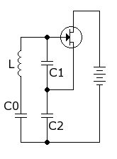
The Clapp oscillator uses a single inductor and three capacitors to set its frequency. The Clapp oscillator is often drawn as a Colpitts oscillator that has an additional capacitor (C0) placed in series with the inductor.[3]
The oscillation frequency in Hertz (cycles per second) for the circuit in the figure, which uses a field-effect transistor (FET), is

The capacitors C1 and C2 are usually much larger than C0, so the 1/C0 term dominates the other capacitances, and the frequency is near the series resonance of L and C0. Clapp's paper gives an example where C1 and C2 are 40 times larger than C0; the change makes the Clapp circuit about 400 times more stable than the Colpitts oscillator for capacitance changes of C2.[4]
Capacitors C0, C1 and C2 form a voltage divider that determines the amount of feedback voltage applied to the transistor input.
Although the Clapp circuit is used as a variable frequency oscillator (VFO) by making C0 a variable capacitor, Vackář states that the Clapp oscillator "can only be used for operation on fixed frequencies or at the most over narrow bands (max. about 1:1.2)."[5] The problem is that under typical conditions, the Clapp oscillator's loop gain varies as f −3, so wide ranges will overdrive the amplifier. For VFOs, Vackář recommends other circuits. See Vackář oscillator.
Practical example edit

The schematic shows an example with component values.[6] Instead of field-effect transistors, other active components such as bipolar junction transistors or vacuum tubes, capable of producing gain at the desired frequency, could be used.
The common drain amplifier has a high input impedance and a low output impedance. Therefore the amplifier input, the gate, is connected to the high impedance top of the LC circuit C0, C1, C2, L1 and the amplifier output, the source, is connected to the low impedance tap of the LC circuit. The grid leak C3 and R1 sets the operating point automatically through grid leak bias. A smaller value of C3 gives less harmonic distortion, but requires a larger load resistor. The supply current for J1 flows through the radio frequency choke L2 to ground. The oscillator radio frequency current uses C2, because for the oscillator frequency this component has less reactance. The load resistor RL is part of the simulation, not part of the circuit.
References edit
- ^ Clapp, J. K. (March 1948). "An inductance-capacitance oscillator of unusual frequency stability". Proc. IRE. 367 (3): 356–358. doi:10.1109/JRPROC.1948.233920. S2CID 51652881.
- ^ Vackář, Jiri (December 1949). LC Oscillators and their Frequency Stability (PDF) (Report). Prague, Czechoslovakia: Tesla National Corporation. Tesla Technical Report. Archived from the original (PDF) on 2009-01-24. Retrieved 2008-12-20.
- ^ Department of the Army (1963) [1959]. Basic Theory and Application of Transistors. Dover. pp. 171–173. TM 11-690.
Modification of the Colpitts oscillator by including a capacitor in series with winding 1–2 of the transformer results in the Clapp oscillator.
- ^ Clapp 1948, p. 357
- ^ Vackář 1949, pp. 5–6
- ^ Hayward, Wes (1994). "Figure 7.8 The Clapp variation of the Colpitts oscillator". Introduction to Radio Frequency Design. US: ARRL. p. 274. ISBN 0-87259-492-0.
Further reading edit
- Ulrich L. Rohde, Ajay K. Poddar, Georg Böck "The Design of Modern Microwave Oscillators for Wireless Applications ", John Wiley & Sons, New York, NY, May, 2005, ISBN 0-471-72342-8.
- George Vendelin, Anthony M. Pavio, Ulrich L. Rohde " Microwave Circuit Design Using Linear and Nonlinear Techniques ", John Wiley & Sons, New York, NY, May, 2005, ISBN 0-471-41479-4.
- A. Grebennikov, RF and Microwave Transistor Oscillator Design. Wiley 2007. ISBN 978-0-470-02535-2.
External links edit
 Media related to Clapp oscillators at Wikimedia Commons
- EE 322/322L Wireless Communication Electronics —Lecture #24: Oscillators. Clapp oscillator. VFO startup