


Summary
The Common Berthing Mechanism (CBM) connects habitable elements in the US Orbital Segment (USOS) of the International Space Station (ISS). The CBM has two distinct sides that, once mated, form a cylindrical vestibule between modules. The vestibule is about 16 inches (0.4 m) long and 6 feet (1.8 m) across. At least one end of the vestibule is often limited in diameter by a smaller bulkhead penetration.
 | |
| Type | Non-androgynous berthing mechanism |
|---|---|
| Developer | |
| Length | ~16 in (0.4 m)[1] |
| Diameter | ~71 in (1.8 m)[1] |
| First use | 11 October 2000 |
| Active CBM (Type I) | |
| Mass | 540 lb (240 kg) (specified)[1] |
| Active CBM (Type II) | |
| Mass | 685 lb (311 kg) (specified)[1] |
| Passive CBM | |
| Mass | 440 lb (200 kg) (specified)[1] |
The elements are maneuvered to the berthing-ready position by a Remote Manipulator System (RMS). Latches and bolts on the active CBM (ACBM) side pull fittings and floating nuts on the passive CBM (PCBM) side to align and join the two.
After the vestibule is pressurized, crew members clear a passage between modules by removing some CBM components. Utility connectors are installed between facing bulkheads, with a closeout panel to cover them. The resulting tunnel can be used as a loading bay, admitting large payloads from visiting cargo spacecraft that would not fit through a typical personnel passageway.
Design overview edit
All CBM types feature an aluminum ring that is bolted onto the pressure shell during fabrication of the parent module. The bolted joint compresses two concentric o-ring seals: one is silicone (for better temperature performance), and the other is fluorocarbon (for better resistance to scrubbing).[2] A mated pair of rings is primary structure for life-critical pressure loads, so the rings and seals were engineered to the same standards as the module shells.[3] If the primary seals deteriorate, they can be augmented by secondary seals that were designed and qualified as part of the CBM. The secondary seals can be installed as an intravehicular activity (IVA).[4]
Most of the vestibule's volume is reserved for crew passage, and a closeout is typically installed around the perimeter of the hatch as a boundary for the passageway. In most locations, volume is reserved for utility connections outboard of the closeout. The set of utilities is specific to each pair of mated modules.[5]


with qualification part numbers[6]
In addition to its structural characteristics, the ACBM performs and reverses the basic functions associated with berthing:[7]
- Alignment physically constrains motion between the modules in five of the six degrees of freedom as the distance between them changes.[8] The constraints are imposed by successive sets of structural components.[9]
- An indication of readiness to operate capture latches is provided to the RMS operator when the incoming module has been correctly placed within reach of the latches. Ready-to-latch indication is provided by four mechanisms: one in each quadrant, associated with each latch.
- The incoming module is captured by four latches. They draw it through a combined rotation and translation to align the PCBM to the ACBM with a small residual gap.[10]
- A rigid structural connection is established. Each of 16 powered bolts on the ACBM crosses the residual gap to thread into a nut on the PCBM. The bolts are tightened in a multi-stage process that gradually conforms the two flanges, compresses the CBM/CBM seals, and preloads the CBM/CBM joint.
Two functional types were specified for the ACBM.[11] The Type I ACBM, with a complement of 24 independent mechanisms, can be found either axially or radially oriented on the parent module. It can face any of the six orbital orientations,[12] so can be anywhere within a wide range of temperatures at the start of berthing operations.[13]
The Type II ACBM augments the design of the Type I with components to protect its parent module when nothing is berthed on a port. Four of the components are mechanisms that can be deployed to get out of the incoming module's way. Others are removed by the crew after the vestibule is pressurized. The Type II is used where ports would otherwise be exposed for long periods of time, or in directions that experience aggressive pre-berth conditions.[14] The Type II ACBM is found on the radial ports of resource nodes, and can face in any orbital orientation.

The PCBM incorporates fittings and alignment structures corresponding to those on the Type I ACBM. 32 of the fittings are themselves spring-loaded mechanisms, actuated during capture and rigidization by corresponding components of the ACBM.[15] The primary CBM/CBM seal is also part of the PCBM, as are preloaded stand-off/push-off springs to stabilize its relative motion when the CBM/CBM joint is nearly mated.[16]
Two types were specified for the PCBM, differing only in the durability of their seal. The S383 silicon material of the Type I PCBM seal is more forgiving of pre-berth temperature differential between the two modules than the V835 fluorocarbon of the Type II. S383 is also more resistant to atomic oxygen encountered on orbit prior to berthing.[17] The Type II was used to launch small elements in the shuttle payload bay while bolted to an ACBM or to similar flight-support equipment because the V835 material is more resistant to the damaging effects of scrubbing under vibration.[18]
The PCBM is always located on an end of the parent module. It can be attached to a bulkhead or as an end ring on a barrel section of primary structure that is open to vacuum before berthing.[19] PCBMs are attached to modules having a wide range of thermal mass, so can also experience a wide range of initial temperature conditions. By the nature of the operation, the PCBM always faces in the flight orientation opposite that of the ACBM, so the temperature differentials can be significant.[20]
Operations edit
See the Operations Gallery for more graphics. See the Missions Table for individual berthing events.
Post-launch edit

ACBMs require EVA to prepare for first use on orbit. Type I ACBMs, usually found on axial ports, typically have a "shower cap" cover that takes two EVA crew members about 45 minutes to remove and stow. Type II ACBMs, found on Node Radial Ports, require release of launch restraints for the Deployable M/D Covers. Release of the spring-loaded covers requires actuation of Capture Latches to close them again afterwards and, therefore, exercises the Ready-to-Latch Indicators. Including inspection, each Radial Port is budgeted about 15 minutes for a single EVA crew member, assisted by IVA crew to operate the ACBM as necessary.[21][22]
Full-sized elements launched on the NSTS had protective covers over the seal on the PCBM. Two EVA crew members required 40 – 50 minutes each to remove and stow the PCBM's covers, inspecting the seal as they did so, and cleaning it if necessary.[23] Type II PCBMs used as a launch interface were inspected after unbolting, since no covers were installed. For logistics flights, inspection is by camera only.[24][22]
Berthing edit
Preparation edit
The PCBM requires no preparation for berthing beyond what is required post-launch. Preparation of the ACBM for berthing takes about an hour, beginning with selection of supporting utilities (power, data) and sequential activation for each Controller Panel Assembly (CPA). Two CPAs are selected as the Primary and Secondary Master Controllers.
Activation executes Built-in-Test and initializes position counters for the actuators. Each bolt actuator is extended two revolutions, then retracted three to verify operability of both the bolt and the motor. Latches are driven one at a time to the open position which, for Node Radial Ports, deploys M/D Covers. All 20 actuators are set to the operational initial positions (0 revolutions for the bolts, 202° for latches). A remote inspection is conducted to verify that the latches are fully deployed and the mating corridor and surface are clear of obstructions.[25]
Contingencies considered during preparation include cleaning the face of the ACBM ring, and EVA corrective actions involving the M/D Covers as well as the CPA, Capture Latch, and Ready-to-Latch Indicators. Specific resolution procedures are available for the loss of power and communications support to the CBM.[26]
Maneuver edit
The PCBM-equipped module is maneuvered into the capture envelope by a tele-robotically operated Remote Manipulator System (RMS). Two different RMSs have been used to berth modules: the 6-joint Shuttle RMS (SRMS, or "Canadarm") and the 7-joint Space Station RMS (SSRMS, "Canadarm2").

The maneuver operation starts with acquisition of the payload by the RMS End Effector. This step is variously referred to as "capture" or "grappling". During the NSTS era, payloads typically arrived in the Shuttle's Payload Bay. During grapple, the SRMS' joints were "limped", allowing it to conform its posture to the exact location of the payload. The SSRMS typically grapples a free-flying payload that has maneuvered itself to maintain a constant distance and orientation with respect to the ISS. Once grappled, the RMS moves the module by changing its joint angles. The motion of the module must often be choreographed with other moving parts of the ISS such as the Solar Arrays.
Visual feedback on the motion of the PCBM has been provided to the RMS operator by at least two dedicated systems. Early berths were guided using a photogrammetric feedback technique called the Space Vision System (SVS), that was quickly determined unsuitable for general use. The SVS was replaced by a task-dedicated Centerline Berthing Camera System (CBCS), first used on STS-98.[27]
The time required to complete the RMS maneuver depends entirely on the trajectory to be followed and on any operational constraints that must be accommodated. The same is true for all contingency planning. Near the end of the maneuver, the operator negotiates a tight corridor as the PCBM begins to mesh with the ACBM. The operation ends when the RMS Operator either sees four Ready-to-Latch indications on the target ACBM, or concludes that only three can be achieved. Because the RTL is a spring-loaded mechanism, the RMS ends up with stored energy and is left in a state that can resist the separating force.[28]
Mate edit
The two halves of the CBM are nominally joined in three operations:
- Capture acquires and aligns the in-coming PCBM with respect to the geometry of the ACBM
- Nut Acquisition threads each Powered Bolt into its respective nut
- Boltup fully preloads the joint between the two halves
At least two distinct capture protocols have been executed on orbit. Both protocols issue a "first-stage" capture command to an indicated shaft angle between 185° and 187°. First-stage capture ensures that each latch is positioned above its respective fitting, which is operationally verified by evaluating its switch state. The RMS still controls the position and orientation of the element, and the loads exerted by the Capture Latches remain low. Taking about 15 seconds to complete, first-stage capture is restricted to orbital regions where ground controllers can monitor progress in near real time. To control spurious loads when the berthing element is large, the station Attitude Control System may be maintained in free-drift and crew exercise prohibited.[29]
The two protocols differ in how the latches draw the two halves to within reach of the Powered Bolts. During the NSTS era, a single second-stage "capture" command was issued after the SRMS was placed in "test mode". Five stages of capture are executed when using the SSRMS in order to limit the potential for loads building up in its arm booms if off-nominal braking events occur. In either case, capture drives latches to 12° indicated shaft angle in an actuation time of about 108 seconds. In both protocols, the residual energy in the RTLs might cause them to open briefly because the latches are not "hooked" to their fittings until well below the 187° starting position.[30]

Once the operator concludes that the capture process has completed successfully, all 16 Powered Bolts are actuated at 5 rpm with a preload limit of 1,500 lbf (6,700 N). As the Thermal Standoffs begin to contact their respective Strike Plates, the resulting load is reported by each bolt's Load Cell. This "ABOLT" phase terminates individually for each bolt on the basis of torque, revolutions, or indicated load. Bolts finishing earlier can see their indicated load change as subsequent bolts seat their nuts. The operators, who might be ground-based, evaluate the resulting condition to determine whether the loading condition is acceptable. If so, restrictions are lifted on Attitude Control and exercise. The RMS releases (ungrapples) the payload and can proceed to other tasks.[31][32]
If pre-mission Thermal Analysis indicates that the temperature differential between the two CBM halves is excessive, the ABOLT condition is held for an extended period of time. The "thermal hold" allows the two sides to approach a common temperature. The Powered Bolts are then tightened in six steps to their full preload. Each command is issued to four bolts at a time, spaced at 90° intervals. Some steps may, at the discretion of the operator, be executed more than once. The final boltup actuation is budgeted for 60 minutes, but can vary quite a bit depending on how many iterations of incremental preload are executed.[33]
Once the operator determines the boltup process to have completed successfully, the latches are commanded to the "closed" position and the CPAs are deactivated. Power, executive command, and data resources are available for reassignment to other tasks.
Accommodations for several off-nominal situations are inherent in the design of the CBM. Any single bolt failure during the mating operation can be accommodated by the CBM/CBM seal, still permitting the vestibule to hold atmospheric pressure. Any two bolt failures can tolerate mechanical loads, provided they are not next to each other and the vestibule is not pressurized. The loss of any single latch and any single Ready-to-Latch indicator can be tolerated without jeopardizing mission success, and the latches themselves are designed to accommodate the possibility for "brakes on" failure modes in the SRMS. Detailed resolution logic for the loss of power and communication is available, as are resolution sequences for latches that "miss" their fittings or jam at a partial stroke. The contingency procedures in this phase of operations also address abnormal braking of the SSRMS and "rapid safing" if other systems in the ISS or Shuttle required immediate departure.[34]
IVA operations edit

Vestibule outfitting includes equipment setup, leak check, and mechanical reconfiguration. The time and effort required depends on the configuration of the ACBM, the number and type of CBM components to be removed, and on the interfaces to be connected between the two elements. It may be budgeted for as much as ten hours although, in at least some cases, that time might be paused to conduct an extended "fine leak check" by pressure decay before opening the hatch into the vestibule.
Because they overlap the crew corridor through the vestibule, the CPAs must always be cleared away,[35] and it is always necessary to remove any covers across the hatch on the newly berthed element. Where the elements will remain mated for long periods of time, other CBM components may be removed for safe storage or reuse. Node radial ports require an additional 20–40 minutes for the removal and storage of the M/D Cover's Center section. A closeout panel is typically installed around the inner perimeter of the two facing hatch beams, to mitigate the gradual collection of debris around the perimeter of the vestibule.[36]
Detailed contingency operations, addressing both repair and preventive maintenance, were prepared in advance for the internally accessible components. Generalized procedures for pinpointing atmospheric leakage in the vestibule have existed since at least ISS Assembly Stage 4A, as have contingency installation procedures for all three sets of IVA seals. Reports of damage to CPA connectors (both on the ground and on orbit) led to the deployment of risk mitigation procedures on STS-126.[37]
Deberthing edit
Removal of an Element essentially reverses the process of berthing.[38] It varies by the specifics of how the vestibule was configured for operations. The most commonly encountered implementation starts with deoutfitting the vestibule when reconfiguring to deberth a logistics element a from Node Radial Port. The procedure was originally budgeted for two crew members and a duration of 4 hours. It removes items that cross the ACBM/PCBM interface plan (closeouts, utility jumpers, and grounding straps), installs CBM hardware essential to demate operations (e.g., CPA, thermal covers), and closes the hatch.[39]

Pressure decay testing equipment, including sensors and supporting electronics and a Vacuum Access Jumper 35 ft (11 m) in length, are subsequently installed on the inside of the hatch. With these in place, the vestibule is ready for a depressurization period of about 40 minutes, including dwell periods for leak check. The critical (absolute) pressure objective is 2 mmHg (267 Pa) in order to preclude damage to the CBM seals during the demate.[40]
As in pre-berth preparation, supporting utilities are configured to provide for power and data to the CBM. Power is applied, two CPAs are selected for use as the Primary and Secondary master controllers, and the individual motor controllers are initialized. A "DBBoltck" command is issued to the Powered Bolts, and the Capture Latches are individually commanded to 212° shaft angle. The latches are then positioned to their nominal "capture complete" position of 12°. The CBM is either left in a "standby" condition, or powered down.[41]
Release of the PCBM Element from the hard mated condition takes about 90 minutes. It begins with loosening of all 16 Powered Bolts by about 0.4 revolutions, taking less than five minutes.[42] All 16 bolts are required to have a positive residual load after the step is complete.[43] Sets of four bolts are then extracted completely, each set taking about 6:30 to reach a nominal position of 21.6 revolutions. RMS grapple and free drift Attitude Control are required to be in place before removal of the third set. After all 16 bolts have been extracted, the Capture Latches are deployed, allowing the compressed Ready-to-Latch Indicators to thrust against the PCBM's Alignment Guides. The departing element is maneuvered away by the RMS and, on Node Radial Ports, the Deployable M/D Covers are closed. The ACBM is then shut down by removing power from the CPAs.[44]
Resolution for contingencies during demate are generally similar to those for preparation and execution of mating operations. Many of them effectively terminate with instructions for a contingency reberth to allow removal and replacement of CBM components. The effort to re-outfit the vestibule for de-berthing the CBM makes it generally unsuitable for emergency departure.[45]
Opportunities edit
The original design of the ISS called for a Habitat element to be installed on the Nadir-facing port of Node 1 (Unity), and bulkhead penetrations were designed accordingly. As the station matured through the first phases of assembly, Node 3 was planned for that location. It later became apparent that installation on the port-side bulkhead would confer significant operational advantages. Unfortunately, the original routing of utilities inside Node 1 required significant re-work on orbit to enable the change. The large CBM diameter permitted the use of PMA3 as a pressure-containing closeout during the effort, so that feed-throughs could be removed and replaced without EVA. PMA3 was moved during Expedition 21 to the port-side CBM, and "...Potable Water, ISL & 1553 data cabling, and installing IMV [Inter-Modular Ventilation] ducting, cables and hoses..." were connected in preparation for the arrival of Node 3. The reconfigured bulkhead was tested for leakage before moving PMA3 back to its storage location, and Node 3 was installed in the newly prepared location on STS-130.[46]
The depth, diameter, and accessibility of the CBM have also been exploited in support of dispensing CubeSats from the SlingShot deployment system. The framework mounts into the PCBM's interior envelope on logistics vehicles (e.g., Cygnus). The Bishop NanoRacks Airlock Module (NRAL) takes advantage of the robust interface between the ACBM and PCBM to repeatedly berth and deberth a "bell" hosting similar capability.[47]
Developmental history edit

The US space program's concept of berthing was developed to mitigate issues of orbital mechanics that were encountered during the evolution of docking. Although not the first mechanism developed specifically for berthing, the CBM was the first such device designed in the US specifically to assemble structural joints that would hold sea-level pressure. It integrates four archetypical features:
- Pressurized structures experience internal pressure in addition to their other primary loads.[49] They are considered life critical when used as the pressure hull of a crewed compartment. In that context, they receive special attention for issues like loads, leak rate, seal redundancy, and verification practices. They also draw close scrutiny to the effects of their failure.[50]
- External flanges are subject to both mechanical loads and loads induced by pressure in their parent pressure vessels. The relative stiffness of the flange determines how the free end will change shape. Distortions must be accommodated when something is being attached at the flange.[49]
- Moving mechanical assemblies transmit forces differently as their posture changes. Their loads are influenced by internal friction, and often require more iterations of analysis and design than structures. In the case of CBM, the load path includes both the module and the RMS, so can be very complicated.[51]
- Structural joints that resist high vacuum are engineered to strictly limit gaps across the joint, and the conditions under which they are assembled are carefully managed. For the CBM, these issues are compounded during boltup by seal scrubbing as pre-berth deflections are conformed, and by any dust and debris trapped in the joint.[52]
The use of these features on a spacecraft entails special considerations due to the aggressive environment. At the 255 nautical miles (472 km) typical ISS altitude, NASA identifies seven factors for that environment:[53]

- The composition, properties, and condition of the ambient neutral atmosphere. In particular, atomic oxygen (AO) is highly corrosive to many materials. Elastomers, such as the PCBM's face seal, are particularly sensitive to AO. Low pressure and low absolute humidity also impact the coefficient of friction for many material combinations. Exposure to very low pressures also changes the chemical composition of certain materials over time.[54]
- Strongly directional sources and sinks of radiant energy. The mounting, optical properties, and insulation of exposed spacecraft components are engineered to maintain acceptable temperatures. In some cases, the orbital orientation of an entire spacecraft is dynamically controlled to mitigate these effects.[55][56]
- The geomagnetic field can interfere with sensitive electrical components (such as those of the ACBM's sensors, switches, and controllers). The effects can include outright failure as the components are carried through the field.[57]
- Ionized gasses that contaminate and charge exposed surfaces, of which the CBM has many. Most spacecraft deal with this issue by careful grounding of the exposed components.[58]
- Electromagnetic radiation that can alter the energy state of electrons in powered equipment. The motors, sensors, and control electronics such as those on the ACBM are susceptible to these effects unless shielded.[59]
- Meteoroids and orbiting debris, some of which can be both heavy and fast-moving, that can strike the spacecraft. Although the CBM design has been augmented several different ways in this regard, the issue was engineered at the integrated spacecraft level; quantitative requirements are not allocated in either CBM specification.[56][60]
- The balance between gravitational and centrifugal accelerations (often referred to as "zero gravity"), which has substantial implications for verifying the motion of mechanisms on the ground because gravity dominates there. CBM followed typical spacecraft engineering practice, iterating between analysis and test to develop and verify designs for this condition.[51]
Several of these features and factors interacted through a long sequence of decisions about the station's orbit, configuration, plans for growth, launch vehicles, and assembly techniques. The berthing operation finds its origin in programs of the 1960s and 1970s as they explored the practicality of physics related to these issues. The CBM concept itself began to emerge with the first studies of the program in the early 1980s, experienced multiple iterations of concept, and completed development shortly before launch of the first flight element as the 1990s drew to a close.
Origins (prior to c. 1984) edit
The CBM is just one branch in the long evolution of the United States' ability to assemble large spacecraft. At least as early as the late 1950s, the capability had been recognized as "...necessary for building space stations and assembling vehicles in low Earth orbit...". By the end of the Apollo program, standardized rendezvous and docking practices to support it had been proven in practice. The basic challenges of propellant management were well understood, as were control stability and contamination issues resulting from the chase vehicle's propulsive RCS plumes[61] hitting the target vehicle vehicle during proximity operations.[62]

The advent of the Space Shuttle Program mitigated some issues with docking, but introduced new ones. Significant differences between the masses of chase and target vehicles provided for less equal sharing of momentum after contact, and the larger mass of the Shuttle required significantly more braking propellant than was needed during Apollo. Simple coaxial alignment between chase and target inertial properties during terminal approach operations was not possible with the asymmetric Orbiter, which was designed for aerodynamic lift during return from orbit. Impingement of large Shuttle RCS plumes on relatively small target vehicles also disturbed control over target orientation during proximity operations. These issues forced changes in braking strategy on the Shuttle program. Not all strategies were easily implemented in all orbital directions, which threatened the ability to assemble in some of those directions. The use of a long tele-robotic device (the RMS) reduced that threat by moving the point of first touch away from the chase vehicle.[63]
By 1972, requirements analysis for the Shuttle Program estimated that almost 40% of mission objectives would involve assembly by placing a payload into the Orbiter's Payload Bay. It was envisioned at that time that many of the retrieved spacecraft would not be designed for such operations, further raising the importance of solving (or eliminating) issues with docking. The berthing operation was developed to do so: a requirement to gently grasp a nearby spacecraft with near-zero contact velocity was allocated to the Shuttle's planned RMS. Using the RMS to assemble objects on orbit was regarded as a driving requirement for accuracy in both position and orientation of the emerging system.[64]
Although not foreseen at the time of RMS development, this period saw the emergence of requirement topics that would become important to the CBM: the accuracy and precision of RMS control, limitations on its ability to force things into alignment, and the magnitude of structural loads peaking in the booms and joints during capture. These proved to be crucial to the design, qualification, and operation of the mechanism's development.[65]

The SRMS did not accomplish its first retrieval and payload bay berth until STS-7 in June, 1983. The date of first operation was two months after submission of final reports by the eight contractors of NASA's Space Station Needs, Attributes, and Architectural Options Study. Even though no flight results were available when the final study reports were written, at least three of them identified "berthing" as the primary means of assembling a Space Station from pressurized modules delivered in the Shuttle's payload bay. Of the concepts described and illustrated, none strongly resemble the eventual design of the CBM, and little discussion of the technical details is readily available.[66]
In early 1984, the Space Station Task Force described a Berthing Mechanism that would attenuate the loads incurred when two modules were maneuvered into contact with each other, followed by latching. Contact conditions were identified as important, but were not quantified at that time. The same is true for the diameter of the internal passageway. Internal connection of utilities between the modules was explicitly required, as was "androgyny". A standardized Berthing Mechanism was perceived as an external flange on module ports, and a "6-port Multiple Berthing Adapter" roughly corresponded to the eventual Resource Node concept. Deflections induced by internal pressure acting on radially-oriented ports of cylindrical modules became recognized as a critical developmental issue.[67] The Task Force's final report also appears to be among the earliest references to "common...berthing mechanisms".[68]
Advanced Development/Phase B (c. 1985 – c. 1988) edit

In parallel with the on-going system-level configuration studies, NASA anticipated that concept development projects for advanced docking and berthing mechanisms "...to substantially reduce docking loads (velocities less than 0.1 ft/sec) and provide payload berthing capabilities...will be initiated beginning in Fiscal Year 1984."[70]
The Berthing Mechanism Advanced Development program actually started in 1985, leading to full-scale testing in the Six-Degree-of-Freedom test facility at Marshall Spaceflight Center (MSFC). In that effort, "common" appears to have meant that a single family of mechanism designs accomplished both berthing and docking (inheriting the divergent requirements for both) and that any member of the family could join with any other member. "Active" and "passive" referred to whether mechanisms were provided for attenuation of residual kinetic energy after docking. Motor-deployed capture latches of two different designs (fast- and slow-acting, having short- and long-reach, respectively) were mounted on the outboard radius. Outward-oriented guide petals were also located on the outboard radius, giving the mechanism an overall diameter of about 85 inches.[71]

Structural latching was accomplished by a "bolt/nut structural latch" of 0.500 inch nominal diameter. Designed for a tensile load of 10,000 lbf (44,500 N), both the bolt and nut were fabricated from A286 steel, coated with a tungsten disulfide dry film lubrication as specified by DOD-L-85645. Bolt/nut locations alternated in orientation around the perimeter of the 63-inch diameter pressure wall and the faces of both rings included seals, so that the mechanism was effectively androgynous at the assembly level. The bolts were designed for manual actuation, using sealed drive penetrations through the bulkhead. An option for motorized torquing was identified, but not designed. The bolt could be tightened from either the head side, or the nut side. Neither the torque nor the uncertainty in preload are reported in the available documentation.[73]
One of the study's four variants incorporated an aluminum bellows, allowing a loop of modules to be closed. Tension loads caused by internal pressure were carried across the bellows by a continuous cable loop threaded through 47 pulleys arrayed around the outside of the bellows. Not all of the issues with the bellows design appear to have been fully resolved by the end of the developmental test series.[74]
Although the dimensions accommodated internal utility connections and a 50-inch square hatchway, the mechanism envelope had limited compatibility with the eventual recessed Radial Port locations on USOS Resource Nodes. The apparent incompatibility with Radial Port locations might be explained by the as-yet unstable configuration of the Nodes, being shown as spherical 10-ports modules in some configurations, but cylindrical 3-port modules in others. Many other features of the baseline station configuration of the time also appear quite different from the eventual ISS.[75]
Space Station Freedom (c. 1989 – c. 1992) edit

As 1990 approached, the size of the CBM had been stabilized by a specific engineering approach to the design of modules. Indirectly constrained by the circular cross-section of the NSTS Payload Bay, the internal volume of the module was divided into eleven regions. A center aisle running the length of the module is surrounded by four banks of equipment. The equipment banks meet along four lines running nearly the full length of the pressure shell. Immediately outboard of those points, wedge-shaped utility volumes run parallel to the aisle. The utility runs allow them to be tapped from many stations along their length. Other equipment, some of which facilitated utility connection between modules after they are mated on orbit, is more efficiently packaged in the endcone volumes than in the cylindrical portion of the module. Penetrations for these utility runs to connect between modules received significant attention in the layout of the vestibule and, therefore, of the CBM.[76]
Each bank of equipment was divided into "racks" of standard size that could be installed on orbit in order to repair, upgrade or extend the station's capability. Racks holding related equipment could be integrated and acceptance tested on the ground before launch. This approach to integration facilitated a higher level of verification than would have been available using replacement of smaller components, providing for "...easy reconfiguration of the modules over their life span of 30 years." It also permitted the architecture to accommodate the subsequent change in orbital inclination by moving some of the heavy racks off the initial launch of the module. The distinctive size and shape of both the common hatch and CBM enabled this concept of module integration because they permitted movement of the large racks into, and out of, the modules while on orbit.[77]

Other system-level decisions in this time frame also affected the eventual design of the CBM. The idea of a "common" mechanism for both docking and berthing appears to have been discarded, and major mechanisms specific to each of those distinct operations were identified. The concept of a "common" module pressure shell with a range of Radial Port configurations, still being studied by NASA at least as late as 1991, was discarded in favor of dedicated "Resource Nodes" having four Radial Ports near one end of a cylindrical pressure shell. Closure of the "module pattern" was deferred from the initial system-level design by 1992, eliminating the bellows-based variant of the PCBM.[78]
By the early 1990s, a more detailed picture of the CBM began to emerge. The initial release of the PCBM development specification was in October 1991, followed by that of the CBM/PE ICD in February, 1992 and the ACBM development specification in January, 1993.[79] Several elements of the Advanced Development concept were retained with little change. The bolt/nut structural latch and 4-bar capture latches remained, although the bolt diameter had increased to 0.625 inches (15.9 mm). Both the bolts and the capture latches were motorized with manual backup being available, although the individual mechanisms were still driven by way of sealed couplings that passed through the bulkhead. The term "active" had evolved to mean the co-location of all powered devices on the side of the interface already present on orbit when the mating operation took place.[80]
Other features had been changed more significantly since the Advanced Development concept. "Androgyny" had been discarded: all 16 bolts were collected on the same side of the CBM/CBM interface, and the nut side was no longer described as being drivable. An 8-channel multiplexing motor controller could be remotely switched between latches, with two controllers required for each module having an ACBM. Differential pressure sensors had been included to monitor potential leak locations. Until it was cancelled, the Passive Flexible CBM still had an aluminum bellows, but the cable/pulley concept had been replaced by a set of 16 powered struts, driven by the multiplexing motor controller. The CBM/CBM seal design was a "face" design, on one side of the interface only. Alignment guides were deployable, and their orientation was reversed to face inward. The four capture latches had acquired friction clutches, allowing them to be back-driven.[80]
New features emerged in this time frame. A debris cover had been added to the ACBM concept. It was a full-diameter unit of a single piece, removed and replaced with the RMS. Attachment of the rings to their bulkheads had been defined as a 64-bolt pattern, but no differentiation of the bolt pattern is mentioned in any of the sources. A shear tie had been added to the design to carry loads parallel to the CBM/CBM interface plane.[80]
Transition to ISS (1993 – c. 1996) edit
By December 1990, Space Station Freedom's cost estimate had risen from the 1984 estimate of $8 billion to reach $38 billion. Although the estimate was reduced to $30 billion by March of the following year, calls to restructure or cancel the program were prominent in Congress. In March 1993, NASA Administrator Dan S. Goldin communicated that President Clinton wanted "...the current Space Station redesigned as part of a program that is more efficient and effective...[to]...significantly reduce development, operations, and utilization costs while achieving many of the current goals...".[81]
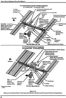
The redesign team submitted their final report in June 1993, describing three distinct space station concepts. Each concept was assessed at orbital inclinations of 28.5 and 51.6 degrees to expose any issues of support from the US and Russian launch complexes, respectively. None of the three configurations precisely matches the design of the ISS as it exists today, although some of them bore strong resemblance to the eventual configuration. The CBM was the only explicitly identified structural/mechanical subsystem included in all options at all inclinations. An increased exploitation of vestibule volume for utility connections was recommended for all options in order to decrease EVA time. Removal of automated controllers, motors, and latch mechanisms was conceptually identified as an option for one of them.[82]
The specific conceptual designs that emerged from the Task Force were soon overcome by events. By late 1994, the US, Russia, and International Partners agreed in principle to merge their national efforts into a single "international [sic] Space Station" project. The cooperation led to hybridized assembly operations such as installation of the docking module atop the Orbiter Docking System on STS-74. This blurred common distinctions between berthing and docking, being positioned by the RMS but actuated by Orbiter thruster firings.[83]
Both CBM specifications were completely re-written in 1995 (PCBM) and 1996 (ACBM) as part of the transition process. This period also saw the splitting of the ICD into dedicated Part 1 (interface requirements) and Part 2 (physical and functional definition) at Revision D (June 1996).[79] By the time a final framework for the international effort was contractually established in December 1996, the first CBM simulators had already been delivered to NASA.[84]
Qualification (c. 1994 – 1998) edit
Having been specified independently, compliance for most requirements of the ACBM and PCBM was verified separately.[85] In addition to assembly-level activities for the ACBM and PCBM, compliance data were generated for subassemblies such as the Capture Latch, Powered Bolt, Powered Bolt Nut, and Ready to Latch Indicator.[86] For example, the Powered Bolt and Nut functionality was qualified by component-level tests that included ambient functional, random vibration, thermal vacuum, and, for the bolt, thermal cycle.[87] Load tests at the yield and ultimate static conditions were conducted at the component level, as were dynamic conditions. The success criteria for these tests were generally based on the torque required to establish and relieve preload, on electrical continuity, and on the accuracy of the bolt's load cell.[88]
In contrast, at least 11 specified verification activities required conjoint verification of mating and/or demating the two sides.[89] Of those, five called for analysis validated by test and/or demonstration that required a specific combination of circumstances and interfaces. For example, the specifications directed capture to be qualified "...by analysis under dynamic loads imposed by the SRMS and SSRMS...validated by assembly-level test that includes variation of performance resulting from temperature and pressure on the ACBM and PCBM and on their interfacing structures."[90] Boltup analyses of the ACBM/PCBM interface, and subsequent leakage, required similar validation by element- and assembly-level tests that included the distorting effects of pressure and temperature. End-to-end demonstrations were also required at the assembly level to verify "...mechanical functionality...without interruption from accomplishment of ready-to-latch indication and capture."[91]

Imposing the combined effects of capture dynamics and distortions required iterations of analysis and validating test for each aspect. The dedicated test setup was developed in three parallel threads:[48]
- Contact dynamics analysis of early CBM versions had begun by 1992, and was incorporated into MSFC's RMS Model for use in Boeing's CBM model development tests. The model was based on the "method of soft constraints", assessing "...intersection or penetration between the corresponding surfaces and calculating mutually perpendicular forces proportional to the depth of penetration". Preliminary model validation testing for these "rebound" forces and subsequent accelerations was conducted in MSFC's Contact Dynamics Laboratory from 1992 through at least 1997.[93] The loads were locally linearized and imposed on the back end of a PCBM test article in the conjoint tests and demonstrations by a counter-balanced "Resistive Load System" suspended from the top of MSFC's V20 Vacuum Chamber.[94]
- Temperature predictions were based on standard thermal analysis modeling techniques. The model was validated by stand-alone thermal balance testing of both assemblies at AEDC's 12V Thermal Vacuum/Solar Simulation Chamber in 1995/96. These ensured use of the correct interface conductances, internal re-radiation, and internal thermal capacitances. Validation was supported by select contact conductance testing, reducing the number of variables to be resolved in thermal balance.[95] Temperatures were imposed during assembly-level qualification testing by a combination of strip heaters, cryogenic shrouds, and direct LN2 Injection.[96]
- Pressure-induced deflections of pressurized elements were estimated by finite element modeling of their primary pressure shells, which led to validating pressure tests in mid-1996. For CBM assembly-level testing, the 16 foot (4.9 m) Active Pressure Vessel (APV) emulated boundary conditions on a flight-like radial port berthing plate. Emulation used 32 external structural doublers ranging in thickness from 0.125–1.00 inch (3.2–25.4 mm), 32 internal struts and 16 pneumatic actuators to tailor stiffness, constrain deflections, and apply local radial loads, respectively. The simpler 9 foot (2.7 m) Passive Pressure Vessel emulated an axial port. Manufacturing of the APV overlapped with discovery of negative margins in the design of Node 1 radial berthing plates. Redesign of the plate could not be accommodated in the APV's manufacturing schedule. It was compensated for by the relative rotation of nut acquisition commands during test.[97]

Setup for the assembly level test began with chamber modifications in August 1996, with the two pressure vessels being delivered for characterization testing in December. Integrated checkout of the assembled setup in the V20 chamber began with baseline testing of developmental CBM hardware in August 1997, and was completed in November of that year. Formal testing ran in three phases from February to September 1998:
- Phase A executed 62 boltup cycles under a range of atmospheric and temperature conditions to evaluate leak rates and Powered Bolt/Nut life cycle.
- Phase B ran 35 partial cycles (capture and nut acquisition) under an expanded range of temperature conditions.
- Phase C conducted five round-trip demonstrations under "challenge" conditions: extreme temperature differentials combined with PCBM positions more distant than those previously executed in hardware.[98]
No leak test was ever failed in this test. The contact dynamics model correlated to the test results with high statistical confidence and was shown to have no discernable sensitivity to deflections. Wear-out signatures for the Powered Bolt were identified and validated, and several integration issues were identified and resolved through minor re-designs. Significant issues with test-specific off-loading of gravitational effects were encountered, ultimately leading to changes in flight procedures. Nominal and contingency procedures were investigated and, in some cases, extensively revised prior to flight operations.[99]
Tests were subsequently conducted in the facility to qualify the IVA seals, and to support resolution of mission operations issues about bolt reach, contact corridors for alignment, RTL clearance, M/D Cover clearance, and RTL activation. The facility also provided real-time support for the first three flight uses of the CBM to assemble the ISS on orbit.[100]
Field modifications (c. 2000 – present) edit

- The decision to install Node 3 on the port-facing CBM of Node 1, instead of the originally-planned Nadir-facing orientation, resulted in "...a unique circumstance: an exposed axial port berthing mechanism. Because this had never been planned for, a new design was developed...similar to the forward facing radial port...to provide a deployable shield to cover the exposed areas." The unique covers were installed during EVA #4 of Expedition 50.[101]
- In late 2017 and early 2018, modifications were made to the attachment of CPAs to the hatch beams on two Nadir-facing ports. These modification allowed for rotation of CPAs "...into the vestibule rather than requiring that the crew remove them completely after a vehicle arrives. This will save both crew time and stowage space during a berthed mission. The CPAs must be installed for proper CBM operation during berthing activities, but they obstruct the pathway into the vehicle once the hatch is opened, so they need to be moved out of the corridor prior to cargo operations."[35]
Galleries edit
Design edit
-
 Module pattern configuration studies continued during the Advanced Development phase. The quasi-spherical nodes of some options, such as the Triangular Tetrahedral pattern shown here, would have had significantly different implications for CBM development. See Smith, et al. (2020) §V for a discussion of how the radial port (and CBM) are influenced by the pressure shell design.[6]
 -
 Major elements of the pressure-containing primary structure of ISS' Node 1 Unity. The ACBM rings act as external flanges on the berthing plates (bulkheads) when no PCBM is present. See Zipay, et al. (2012) for an extensive discussion of the pressure shell.[6]
 -
 The size of the CBM interacts with the radial orientation to produce the deflections in this artist's rendering. Although shown for clarity at the ACBM's "outboard" flange in this artist's rendering, these deflections actually apply where the ACBM's ring is bolted to the Pressurized Element (with the ring installed). They are "conformed" when the two halves of the CBM are bolted together at "hard mate".[6][102]
 -
 A vestibule is composed of an ACBM ring (1) mounted to a flanged bulkhead (3) and a PCBM ring (2) mounted to a flanged bulkhead or barrel section (4). The rings, both machined from 2219 Aluminum forgings, mate at a "molded seal" (5); each ring is sealed at its inboard end by a pair of concentric o-rings (6). Shown here "mid-span" between the Powered Bolt locations, three internal loads try to pry the joint open: atmospheric pressure (Fa) (15.2 psia), seal compression (Fs) and flange conformance (Fc). This artist's rendering of a generic cross-section also shows (in blue) where air can leak to the vacuum of space.[6][67][103]
 -
 The CBM/CBM joint is clamped by 16 equally-spaced Powered Bolts (1). The fine-threaded bolt shaft is machined from Inconel 718, with a nominal diameter of 0.625 in (15.9 mm). Each bolt threads into a nut encapsulated by a nutplate (2). The nut is made of Nitronic 60 steel, internally lubricated with Vitro-lube NPI-1220C.[104] The bolt was qualified to a preload (Fp*) of 19,300 lbf (85,900 N), actuated by torque (τ) from an actuator (3) having a maximum sustained output of 1,600 lb⋅in (180,000 mN⋅m).[105] The effective preload can change (Fcte) after berthing by the difference between coefficients of thermal expansion of bolts and flanges. Each bolt aligns with the separating load (Ft) of a spring-loaded thermal standoff (4), also affected by post-berth temperatures. This artist's rendering of a generic cross-section also shows (in blue) leak paths unique to the bolt locations.[6][103]
 -
 A stripped vestibule photographed during STS-092. Powered Bolt Nuts and the area reserved for their IVA seal caps are visible (1), as are a CPM/PE leak check port (2) and a CBM/CBM grounding strap (3). This is one of two Node 1 axial ports: the closeout brackets (4) are tucked into the hatch beam rather than on its face. "Butter dish" IVA seals cover the powered bolts, and covers protect the CBM/CBM IVA seal lands (6) on the inward faces of the outboard flanges. Mounts (7) and tensioners (8) for the covers are also shown.[6][106]
 -
 Almost a full quadrant of mated CBM rings can be seen in the vestibule leading to PMA2, showing the thickness of the Gask-o-seal (1) between them. The rings are rigidly joined by 16 nuts (2), each having been threaded into by a Powered Bolt to carry axial and bending loads between mated modules. Of the bolt, only the actuator (3) is visible. Also seen are a capture latch (4), a capture fitting (5), some electrical/control harnessing, and a quadrant's complement of mated alignment guides.[6][107]
 -
 Insertion of the first system rack into the US Lab "Destiny" demonstrated the sizing logic for both the common hatch and the CBM, that followed from the architectural approach described in Hopson, Aaron & Grant (1990). The ACBM ring had not yet been installed when this photo was taken in March, 1998.[6]
 -

-
 The ID of the inboard flange is "scalloped" in 16 places to fit Powered Bolt Actuators, as highlighted (1) on Node 2 during assembly in 2004. The ID pattern has 112 bolts, for a total of 208 fasteners at that joint. The hatch beam (2) shows mounting holes for a controller panel assembly (CPA), and M/D Center Section standoff brackets (3) are installed. The flange cover will be removed before flight.[6][109]
 -

-
 The Z1 PCBM ring (1) before installation in 1998. Viewed here from the PE side, the silicone (2) and fluorocarbon (3) O-rings are already installed under the inboard flange. The attachment bolt holes (4) are visible around the inboard flange, and indexing pins protrude to ensure that the seals compress uniformly as it is bolted into place.[6][108]
 -
-
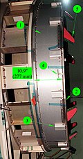
 The seal between the two CBM sides is a four-segment, two-sided molded design. Attached to the PCBM ring by 36 bolts, each segment's aluminum substrate is 0.250 in (6.4 mm) thick. Three beads are molded into each segment, ranging in height from 0.044 in (1.1 mm) (inner bead) to 0.050 in (1.3 mm) (outer). A little more than 1/8th of the circumference is shown here during STS-124; the segment "interlock" joint (1) is highlighted in the inset. The photo also shows the ends of two thermal standoffs (2), alignment guides (3), a capture fitting (4), a bumper (5) and the ends of two Powered Bolt Nuts (6). Small holes and sunken channels between the seal beads permit leak testing of the CBM/CBM joint once mated.[6][111]
 -
 Three stages of alignment are seen in this photo of Kibo's ACBM from STS-124. Bumpers (1), curving over the "high wall", are on radial ports only. All ACBM installations have Alignment Guides (2), and Alignment Pins (3). The constraint is handed off from each stage to its successor while the in-coming module is moved with the RMS. Final alignment happens when the pins seat in their respective PCBM sockets during capture. They carry shear and torsion loads across the interface thereafter.[6][112]
 -
 The tip of a Powered Bolt (1) peeks out from the outboard flange on Kibo's radial port during STS-124. The Capture Latch (2) is at or near "capture ready". Its tip stands over 5” above the flange here, but reaches further during its sweep. A Ready-to-Latch Indicator (3) will be depressed by the PCBM's Alignment Guide during the RMS maneuver. [6][113]
 -
![Front and side elevation diagrams of the Capture Latch (1) in the closed position. The underside of the Ready-to-Latch Indicator (2) shows one set of springs that will be compressed by the PCBM Alignment Guide during capture. The cables (3) are for the latch and its limit switch, the RTL, and nearby Powered Bolts.[6][114]](//upload.wikimedia.org/wikipedia/commons/thumb/2/24/ACBM_Capture_Mechanisms_%28Annotated%29.jpg/120px-ACBM_Capture_Mechanisms_%28Annotated%29.jpg) Front and side elevation diagrams of the Capture Latch (1) in the closed position. The underside of the Ready-to-Latch Indicator (2) shows one set of springs that will be compressed by the PCBM Alignment Guide during capture. The cables (3) are for the latch and its limit switch, the RTL, and nearby Powered Bolts.[6][114]
Front and side elevation diagrams of the Capture Latch (1) in the closed position. The underside of the Ready-to-Latch Indicator (2) shows one set of springs that will be compressed by the PCBM Alignment Guide during capture. The cables (3) are for the latch and its limit switch, the RTL, and nearby Powered Bolts.[6][114] -
![The Capture Latch is a rotating four-bar linkage. Attached to the chassis (1), an actuator (not shown) applies torque to the drive axle (2), rotating the drive arm (3). The arm pushes the "dogleg assembly" (4) around, which torques the outer clevis of the Capture Arm (5). The Capture Arm rotates about the end of the Follower linkage (6), the other end of which rotates about the axle. When deployed, the latch trips a switch (not shown). When fully closed it is locked by a hook (7) passing through the hole (8) in the Capture Arm.[6][115]](//upload.wikimedia.org/wikipedia/commons/thumb/8/85/Capture_Latch_2-view_Anno.jpg/120px-Capture_Latch_2-view_Anno.jpg) The Capture Latch is a rotating four-bar linkage. Attached to the chassis (1), an actuator (not shown) applies torque to the drive axle (2), rotating the drive arm (3). The arm pushes the "dogleg assembly" (4) around, which torques the outer clevis of the Capture Arm (5). The Capture Arm rotates about the end of the Follower linkage (6), the other end of which rotates about the axle. When deployed, the latch trips a switch (not shown). When fully closed it is locked by a hook (7) passing through the hole (8) in the Capture Arm.[6][115]
The Capture Latch is a rotating four-bar linkage. Attached to the chassis (1), an actuator (not shown) applies torque to the drive axle (2), rotating the drive arm (3). The arm pushes the "dogleg assembly" (4) around, which torques the outer clevis of the Capture Arm (5). The Capture Arm rotates about the end of the Follower linkage (6), the other end of which rotates about the axle. When deployed, the latch trips a switch (not shown). When fully closed it is locked by a hook (7) passing through the hole (8) in the Capture Arm.[6][115] -
![The ACBM's Ready-to-Latch (RTL) indicator is a spring-loaded device, depressing in combined rotation and plunge by the PCBM Alignment Guide. It transmits a signal to the RMS Operator through the ACBM Controller Panel Assembly. Each of the two spring-loaded degrees of freedom can be locked out for maintenance. One RTL is associated with each Capture Latch.[6][116]](//upload.wikimedia.org/wikipedia/commons/thumb/f/fc/Ready-to-Latch_Indicator_Exploded_View.jpg/120px-Ready-to-Latch_Indicator_Exploded_View.jpg) The ACBM's Ready-to-Latch (RTL) indicator is a spring-loaded device, depressing in combined rotation and plunge by the PCBM Alignment Guide. It transmits a signal to the RMS Operator through the ACBM Controller Panel Assembly. Each of the two spring-loaded degrees of freedom can be locked out for maintenance. One RTL is associated with each Capture Latch.[6][116]
The ACBM's Ready-to-Latch (RTL) indicator is a spring-loaded device, depressing in combined rotation and plunge by the PCBM Alignment Guide. It transmits a signal to the RMS Operator through the ACBM Controller Panel Assembly. Each of the two spring-loaded degrees of freedom can be locked out for maintenance. One RTL is associated with each Capture Latch.[6][116] -
![The internally-located capture components are shown here at an intermediate capture position. The Ready-to-Latch indicator has already been plunged, but has not yet been rotated under the PCBM Alignment Guide. This frame was taken from a real-time contact dynamics simulation created at JSC.[6][117]](//upload.wikimedia.org/wikipedia/commons/thumb/3/3c/Internal_Capture_Components.jpg/120px-Internal_Capture_Components.jpg)
-
![Powered Bolt upper housings are shown in this pre-flight test of the Cupola from late 2008. Actuators are not used in this equipment. Engagement of strikeplates (1) with thermal standoffs (2) and alignment pins (3) with sockets (4) is imminent. The inset, from a photo taken two years later, shows the back of the Powered Bolt Assembly's Upper Housing.[6][118]](//upload.wikimedia.org/wikipedia/commons/thumb/5/56/Cupola_Leak_Test_1_Setup_%28Annotated%29.jpg/120px-Cupola_Leak_Test_1_Setup_%28Annotated%29.jpg) Powered Bolt upper housings are shown in this pre-flight test of the Cupola from late 2008. Actuators are not used in this equipment. Engagement of strikeplates (1) with thermal standoffs (2) and alignment pins (3) with sockets (4) is imminent. The inset, from a photo taken two years later, shows the back of the Powered Bolt Assembly's Upper Housing.[6][118]
Powered Bolt upper housings are shown in this pre-flight test of the Cupola from late 2008. Actuators are not used in this equipment. Engagement of strikeplates (1) with thermal standoffs (2) and alignment pins (3) with sockets (4) is imminent. The inset, from a photo taken two years later, shows the back of the Powered Bolt Assembly's Upper Housing.[6][118] -
![A partially-disassembled CBM Powered Bolt, showing both ends of the shaft (1), the lower housing (2) that nestles into the ACBM ring, the drive sleeve (3) and its spline interface with the shaft, and the upper housing (4). The upper housing and drive sleeve can be removed without demating the vestibule to install a spline lock under an IVA seal "butter dish". The spline lock prevents the bolt from backing out.[6][119]](//upload.wikimedia.org/wikipedia/commons/thumb/7/7d/CBM_Powered_Bolt_Apart.jpg/120px-CBM_Powered_Bolt_Apart.jpg) A partially-disassembled CBM Powered Bolt, showing both ends of the shaft (1), the lower housing (2) that nestles into the ACBM ring, the drive sleeve (3) and its spline interface with the shaft, and the upper housing (4). The upper housing and drive sleeve can be removed without demating the vestibule to install a spline lock under an IVA seal "butter dish". The spline lock prevents the bolt from backing out.[6][119]
A partially-disassembled CBM Powered Bolt, showing both ends of the shaft (1), the lower housing (2) that nestles into the ACBM ring, the drive sleeve (3) and its spline interface with the shaft, and the upper housing (4). The upper housing and drive sleeve can be removed without demating the vestibule to install a spline lock under an IVA seal "butter dish". The spline lock prevents the bolt from backing out.[6][119] -
![Each Powered Bolt "acquires" an Encapsulated Nut (1) to align the threads. It is loaded by a spring (2) retained between washers (3) under a nut plate (4). The plate is located on the back of the PCBM's outboard flange by a pair of dowel pins (5). As the bolt nudges the nut during acquisition, motion of the nut is constrained by tabs on the Floating Washer (6) inside the plate's rectangular hole and by a Spherical Washer (7). A Castellated Nut (8), locked with a Cotter Pin (9), holds the stack together. It attaches to the flange by a pair of Captive Fasteners (10). If the Powered Bolt jams in the Encapsulated Nut, disassembly permits the seized units to be removed and replaced from the ACBM side without depressurizing the vestibule.[6][120]](//upload.wikimedia.org/wikipedia/commons/thumb/a/ab/CBM_Powered_Bolt_Nut_%28Exploded%29.jpg/120px-CBM_Powered_Bolt_Nut_%28Exploded%29.jpg) Each Powered Bolt "acquires" an Encapsulated Nut (1) to align the threads. It is loaded by a spring (2) retained between washers (3) under a nut plate (4). The plate is located on the back of the PCBM's outboard flange by a pair of dowel pins (5). As the bolt nudges the nut during acquisition, motion of the nut is constrained by tabs on the Floating Washer (6) inside the plate's rectangular hole and by a Spherical Washer (7). A Castellated Nut (8), locked with a Cotter Pin (9), holds the stack together. It attaches to the flange by a pair of Captive Fasteners (10). If the Powered Bolt jams in the Encapsulated Nut, disassembly permits the seized units to be removed and replaced from the ACBM side without depressurizing the vestibule.[6][120]
Each Powered Bolt "acquires" an Encapsulated Nut (1) to align the threads. It is loaded by a spring (2) retained between washers (3) under a nut plate (4). The plate is located on the back of the PCBM's outboard flange by a pair of dowel pins (5). As the bolt nudges the nut during acquisition, motion of the nut is constrained by tabs on the Floating Washer (6) inside the plate's rectangular hole and by a Spherical Washer (7). A Castellated Nut (8), locked with a Cotter Pin (9), holds the stack together. It attaches to the flange by a pair of Captive Fasteners (10). If the Powered Bolt jams in the Encapsulated Nut, disassembly permits the seized units to be removed and replaced from the ACBM side without depressurizing the vestibule.[6][120] -
![One of the four Controller Panel Assemblies (CPA) bolted to a hatch beam during STS-102 in 2001. Each CPA has one Capture Latch controller (1), four Powered Bolt controllers (2) and circuitry to condition input power (3). A bracket (4) for installation of the M/D "center section" cover is visible on either side of the CPA. The photograph was taken from the PCBM side of the mated vestibule, looking back into the ACBM. The basic individual controller design is also used for the Carbon Dioxide Removal Assembly's Pump Fan Motor Controller, Vent and Relief Valve, and Internal Thermal Control System valves.[6][121]](//upload.wikimedia.org/wikipedia/commons/thumb/8/8c/CBM_CPA_%28Annotated%29.jpg/120px-CBM_CPA_%28Annotated%29.jpg) One of the four Controller Panel Assemblies (CPA) bolted to a hatch beam during STS-102 in 2001. Each CPA has one Capture Latch controller (1), four Powered Bolt controllers (2) and circuitry to condition input power (3). A bracket (4) for installation of the M/D "center section" cover is visible on either side of the CPA. The photograph was taken from the PCBM side of the mated vestibule, looking back into the ACBM. The basic individual controller design is also used for the Carbon Dioxide Removal Assembly's Pump Fan Motor Controller, Vent and Relief Valve, and Internal Thermal Control System valves.[6][121]
One of the four Controller Panel Assemblies (CPA) bolted to a hatch beam during STS-102 in 2001. Each CPA has one Capture Latch controller (1), four Powered Bolt controllers (2) and circuitry to condition input power (3). A bracket (4) for installation of the M/D "center section" cover is visible on either side of the CPA. The photograph was taken from the PCBM side of the mated vestibule, looking back into the ACBM. The basic individual controller design is also used for the Carbon Dioxide Removal Assembly's Pump Fan Motor Controller, Vent and Relief Valve, and Internal Thermal Control System valves.[6][121] -
![The six-member Expedition 59 crew poses for a portrait looking through the vestibule between Node 1 (Unity) and Northrop Grumman's Cygnus commercial space freighter. The closeout covers a full complement of rotated CPAs.[6][35]](//upload.wikimedia.org/wikipedia/commons/thumb/0/04/Expedition_59_crew_inside_the_Cygnus.jpg/120px-Expedition_59_crew_inside_the_Cygnus.jpg) The six-member Expedition 59 crew poses for a portrait looking through the vestibule between Node 1 (Unity) and Northrop Grumman's Cygnus commercial space freighter. The closeout covers a full complement of rotated CPAs.[6][35]
The six-member Expedition 59 crew poses for a portrait looking through the vestibule between Node 1 (Unity) and Northrop Grumman's Cygnus commercial space freighter. The closeout covers a full complement of rotated CPAs.[6][35] -
![Each Active CBM has four Controller Panel Assemblies. With five ACBM's, Node 3 carried 20 such units to orbit. As seen here on an axial ACBM (1) CPA's are cantilevered across the hatch. In this photo taken at KSC in 2009, the proximity of M/D petals to the CPA is also visible on a radial port (2). Another port (3) has already been equipped with the M/D Center Section.[6][122]](//upload.wikimedia.org/wikipedia/commons/thumb/c/cf/Node_3_MD_Installing_Anno.jpg/120px-Node_3_MD_Installing_Anno.jpg) Each Active CBM has four Controller Panel Assemblies. With five ACBM's, Node 3 carried 20 such units to orbit. As seen here on an axial ACBM (1) CPA's are cantilevered across the hatch. In this photo taken at KSC in 2009, the proximity of M/D petals to the CPA is also visible on a radial port (2). Another port (3) has already been equipped with the M/D Center Section.[6][122]
Each Active CBM has four Controller Panel Assemblies. With five ACBM's, Node 3 carried 20 such units to orbit. As seen here on an axial ACBM (1) CPA's are cantilevered across the hatch. In this photo taken at KSC in 2009, the proximity of M/D petals to the CPA is also visible on a radial port (2). Another port (3) has already been equipped with the M/D Center Section.[6][122] -
![The large M/D Center Section (1) covers most of the hatch to protect it from the meteoroid/debris environment. It has several straps and openings, depending on installed location. Most covers have a flap (2) over the hatch window, as seen here during STS-120. The flap is restrained by "hook and loop" closure, held with a snap. Each of the four Capture Latches is covered by a spring-loaded deployable petal (3). They open to expose the mechanisms that effect the on-orbit mate.[6][123]](//upload.wikimedia.org/wikipedia/commons/thumb/b/bc/STS120_CBM_Open_Flap_%28Annotated%29.jpg/120px-STS120_CBM_Open_Flap_%28Annotated%29.jpg) The large M/D Center Section (1) covers most of the hatch to protect it from the meteoroid/debris environment. It has several straps and openings, depending on installed location. Most covers have a flap (2) over the hatch window, as seen here during STS-120. The flap is restrained by "hook and loop" closure, held with a snap. Each of the four Capture Latches is covered by a spring-loaded deployable petal (3). They open to expose the mechanisms that effect the on-orbit mate.[6][123]
The large M/D Center Section (1) covers most of the hatch to protect it from the meteoroid/debris environment. It has several straps and openings, depending on installed location. Most covers have a flap (2) over the hatch window, as seen here during STS-120. The flap is restrained by "hook and loop" closure, held with a snap. Each of the four Capture Latches is covered by a spring-loaded deployable petal (3). They open to expose the mechanisms that effect the on-orbit mate.[6][123] -
![The Center Section's multi-layer fabric (1) is suspended by a cable running through pulleys (2) around its perimeter, tensioned by turnbuckles (3). Inserted into ring-mounted clevises (4), the pulleys pull against standoffs (5) that fit into brackets (6) on either side of each CPA. The center section is removed from underneath by the crew to expose the newly berthed module.[6][124]](//upload.wikimedia.org/wikipedia/commons/thumb/d/d2/CBM_MD_Center_Install_%28Annotated%29.jpg/120px-CBM_MD_Center_Install_%28Annotated%29.jpg) The Center Section's multi-layer fabric (1) is suspended by a cable running through pulleys (2) around its perimeter, tensioned by turnbuckles (3). Inserted into ring-mounted clevises (4), the pulleys pull against standoffs (5) that fit into brackets (6) on either side of each CPA. The center section is removed from underneath by the crew to expose the newly berthed module.[6][124]
The Center Section's multi-layer fabric (1) is suspended by a cable running through pulleys (2) around its perimeter, tensioned by turnbuckles (3). Inserted into ring-mounted clevises (4), the pulleys pull against standoffs (5) that fit into brackets (6) on either side of each CPA. The center section is removed from underneath by the crew to expose the newly berthed module.[6][124] -
![The tightly-packed area near one corner of a Radial Port hatch is seen here in a figure from an in-flight maintenance manual. The cable (1) of a Powered Bolt load cell wraps around the upper housing (2) and actuator (3), which are held together by a threaded collar (4). The protective cover (5) and cover mount (6) for the CBM/CBM IVA seal are in the foreground, as is one of the eight clevises (7) for the M/D Cover Center Section. The restraint slot (8) for a Deployable Cover launch lock pin protrudes beyond the CBM/CBM interface plane.[6][125]](//upload.wikimedia.org/wikipedia/commons/thumb/f/f9/CBM_Corner_Closeup.jpg/120px-CBM_Corner_Closeup.jpg) The tightly-packed area near one corner of a Radial Port hatch is seen here in a figure from an in-flight maintenance manual. The cable (1) of a Powered Bolt load cell wraps around the upper housing (2) and actuator (3), which are held together by a threaded collar (4). The protective cover (5) and cover mount (6) for the CBM/CBM IVA seal are in the foreground, as is one of the eight clevises (7) for the M/D Cover Center Section. The restraint slot (8) for a Deployable Cover launch lock pin protrudes beyond the CBM/CBM interface plane.[6][125]
The tightly-packed area near one corner of a Radial Port hatch is seen here in a figure from an in-flight maintenance manual. The cable (1) of a Powered Bolt load cell wraps around the upper housing (2) and actuator (3), which are held together by a threaded collar (4). The protective cover (5) and cover mount (6) for the CBM/CBM IVA seal are in the foreground, as is one of the eight clevises (7) for the M/D Cover Center Section. The restraint slot (8) for a Deployable Cover launch lock pin protrudes beyond the CBM/CBM interface plane.[6][125] -
![The petals (1) deploy outboard when the Capture Latch releases from roller link (2). The pivot point (3) is just outboard of the Capture Latch. Each petal has two launch locks (4) that fit into slots (5) atop the clevises, pockets (6) to accommodate Alignment Guides, and a feature (7) aligned with its respective Ready-to-Latch Indicator (8).[6][126]](//upload.wikimedia.org/wikipedia/commons/thumb/9/91/CBM_MD_Petal_Open_1_Annotated.jpg/120px-CBM_MD_Petal_Open_1_Annotated.jpg) The petals (1) deploy outboard when the Capture Latch releases from roller link (2). The pivot point (3) is just outboard of the Capture Latch. Each petal has two launch locks (4) that fit into slots (5) atop the clevises, pockets (6) to accommodate Alignment Guides, and a feature (7) aligned with its respective Ready-to-Latch Indicator (8).[6][126]
The petals (1) deploy outboard when the Capture Latch releases from roller link (2). The pivot point (3) is just outboard of the Capture Latch. Each petal has two launch locks (4) that fit into slots (5) atop the clevises, pockets (6) to accommodate Alignment Guides, and a feature (7) aligned with its respective Ready-to-Latch Indicator (8).[6][126] -
![The deployable petal is grabbed by the Capture Latch at the tip of the Roller Link (1). If necessary, the link can be released during EVA by loosening a bolt (2). "Locking out" the spring-loaded actuator with a bolt (3) allows the astronaut to "safe" the mechanism before manual operation. The petal structure can be separated from the deployment mechanism with two bolts (4).[6]](//upload.wikimedia.org/wikipedia/commons/thumb/a/a2/MD_Petal_EVA_Anno.jpg/120px-MD_Petal_EVA_Anno.jpg) The deployable petal is grabbed by the Capture Latch at the tip of the Roller Link (1). If necessary, the link can be released during EVA by loosening a bolt (2). "Locking out" the spring-loaded actuator with a bolt (3) allows the astronaut to "safe" the mechanism before manual operation. The petal structure can be separated from the deployment mechanism with two bolts (4).[6]
The deployable petal is grabbed by the Capture Latch at the tip of the Roller Link (1). If necessary, the link can be released during EVA by loosening a bolt (2). "Locking out" the spring-loaded actuator with a bolt (3) allows the astronaut to "safe" the mechanism before manual operation. The petal structure can be separated from the deployment mechanism with two bolts (4).[6] -
![PMA-3's location on the nadir port of Node 1 Unity shows the tight fit between a berthed module and the deployed M/D Petal.[6]](//upload.wikimedia.org/wikipedia/commons/thumb/c/ca/PMA3_on_Node_1_Nadir.jpg/120px-PMA3_on_Node_1_Nadir.jpg) PMA-3's location on the nadir port of Node 1 Unity shows the tight fit between a berthed module and the deployed M/D Petal.[6]
PMA-3's location on the nadir port of Node 1 Unity shows the tight fit between a berthed module and the deployed M/D Petal.[6] -
![The petals are locked in place for launch by a pin (1) inserted through a fitting (2) on the M/D Center Section clevis (3). Release is effected by a T-handle (4), which is pulled (5) away from the ACBM. It can be re-locked by pushing (6) the pin back into the fitting.[6]](//upload.wikimedia.org/wikipedia/commons/thumb/c/cd/MD_Petal_Launch_Lock.jpg/120px-MD_Petal_Launch_Lock.jpg) The petals are locked in place for launch by a pin (1) inserted through a fitting (2) on the M/D Center Section clevis (3). Release is effected by a T-handle (4), which is pulled (5) away from the ACBM. It can be re-locked by pushing (6) the pin back into the fitting.[6]
The petals are locked in place for launch by a pin (1) inserted through a fitting (2) on the M/D Center Section clevis (3). Release is effected by a T-handle (4), which is pulled (5) away from the ACBM. It can be re-locked by pushing (6) the pin back into the fitting.[6] -
![The petal is typically unlocked during EVA, using a conveniently located strap.[6]](//upload.wikimedia.org/wikipedia/commons/thumb/c/ca/MD_Petal_Unlocking.jpg/120px-MD_Petal_Unlocking.jpg) The petal is typically unlocked during EVA, using a conveniently located strap.[6]
The petal is typically unlocked during EVA, using a conveniently located strap.[6] -
![The CBM/CBM seal, mounted on the face of the PCBM, was covered to protect it from debris when launched in the shuttle. The seal, bolted to the face of the ring, peeks out beyond the cover in the top left corner of the image. Covers, which were removed by pre-berth EVA, are not used for logistics missions.[6][127]](//upload.wikimedia.org/wikipedia/commons/thumb/f/f9/PCBM_Flight_Cover.jpg/120px-PCBM_Flight_Cover.jpg) The CBM/CBM seal, mounted on the face of the PCBM, was covered to protect it from debris when launched in the shuttle. The seal, bolted to the face of the ring, peeks out beyond the cover in the top left corner of the image. Covers, which were removed by pre-berth EVA, are not used for logistics missions.[6][127]
The CBM/CBM seal, mounted on the face of the PCBM, was covered to protect it from debris when launched in the shuttle. The seal, bolted to the face of the ring, peeks out beyond the cover in the top left corner of the image. Covers, which were removed by pre-berth EVA, are not used for logistics missions.[6][127] -
![The CBM/CBM joint has provisions for installation of an IVA seal in case the primary seal fails. Like the primary, it is a segmented molded seal, but has beads only on the outboard face. The beads are squeezed against the inboard faces of the rings by compression plates, fastening into the same bolt pattern used to hold the protective covers.[6][4]](//upload.wikimedia.org/wikipedia/commons/thumb/c/c2/CBM-CBM_IVA_Seal_Before-After.jpg/120px-CBM-CBM_IVA_Seal_Before-After.jpg) The CBM/CBM joint has provisions for installation of an IVA seal in case the primary seal fails. Like the primary, it is a segmented molded seal, but has beads only on the outboard face. The beads are squeezed against the inboard faces of the rings by compression plates, fastening into the same bolt pattern used to hold the protective covers.[6][4]
The CBM/CBM joint has provisions for installation of an IVA seal in case the primary seal fails. Like the primary, it is a segmented molded seal, but has beads only on the outboard face. The beads are squeezed against the inboard faces of the rings by compression plates, fastening into the same bolt pattern used to hold the protective covers.[6][4] -
![In the event of a leak at the joint where an ACBM is bolted to its parent module, an o-ring can be installed on the inside. The o-ring is compressed into the groove by a series of compression plates. This particular plate conforms to the joint's scallop.[6][4]](//upload.wikimedia.org/wikipedia/commons/thumb/7/77/ACBM-to-PE_Compression_Plate.jpg/120px-ACBM-to-PE_Compression_Plate.jpg)
-
![The Passive CBM provides for IVA seals where it is bolted to its parent Element. Here, a human finger (1) points to a main IVA seal compression plate, which would be installed over an o-ring. Covers (2) can also be placed over the joint's bolt heads, each of which is a potential leak path through the joint.[6][4]](//upload.wikimedia.org/wikipedia/commons/thumb/7/7b/PCBM-PE_IVA_Seal.jpg/120px-PCBM-PE_IVA_Seal.jpg) The Passive CBM provides for IVA seals where it is bolted to its parent Element. Here, a human finger (1) points to a main IVA seal compression plate, which would be installed over an o-ring. Covers (2) can also be placed over the joint's bolt heads, each of which is a potential leak path through the joint.[6][4]
The Passive CBM provides for IVA seals where it is bolted to its parent Element. Here, a human finger (1) points to a main IVA seal compression plate, which would be installed over an o-ring. Covers (2) can also be placed over the joint's bolt heads, each of which is a potential leak path through the joint.[6][4] -
![The "butter dish" covers seal the leak paths through (and around) Powered Bolts and Powered Bolt Nuts. When used on the ACBM's bolt, the actuator and upper housing are removed and a spline lock is installed inside the dish to keep the bolt from gradually backing out under cyclic loads.[6] [4]](//upload.wikimedia.org/wikipedia/commons/thumb/8/83/CBM_Butter_Dish_Seal.jpg/120px-CBM_Butter_Dish_Seal.jpg)


![Front and side elevation diagrams of the Capture Latch (1) in the closed position. The underside of the Ready-to-Latch Indicator (2) shows one set of springs that will be compressed by the PCBM Alignment Guide during capture. The cables (3) are for the latch and its limit switch, the RTL, and nearby Powered Bolts.[6][114]](http://upload.wikimedia.org/wikipedia/commons/thumb/2/24/ACBM_Capture_Mechanisms_%28Annotated%29.jpg/120px-ACBM_Capture_Mechanisms_%28Annotated%29.jpg)
![The Capture Latch is a rotating four-bar linkage. Attached to the chassis (1), an actuator (not shown) applies torque to the drive axle (2), rotating the drive arm (3). The arm pushes the "dogleg assembly" (4) around, which torques the outer clevis of the Capture Arm (5). The Capture Arm rotates about the end of the Follower linkage (6), the other end of which rotates about the axle. When deployed, the latch trips a switch (not shown). When fully closed it is locked by a hook (7) passing through the hole (8) in the Capture Arm.[6][115]](http://upload.wikimedia.org/wikipedia/commons/thumb/8/85/Capture_Latch_2-view_Anno.jpg/120px-Capture_Latch_2-view_Anno.jpg)
![The ACBM's Ready-to-Latch (RTL) indicator is a spring-loaded device, depressing in combined rotation and plunge by the PCBM Alignment Guide. It transmits a signal to the RMS Operator through the ACBM Controller Panel Assembly. Each of the two spring-loaded degrees of freedom can be locked out for maintenance. One RTL is associated with each Capture Latch.[6][116]](http://upload.wikimedia.org/wikipedia/commons/thumb/f/fc/Ready-to-Latch_Indicator_Exploded_View.jpg/120px-Ready-to-Latch_Indicator_Exploded_View.jpg)
![The internally-located capture components are shown here at an intermediate capture position. The Ready-to-Latch indicator has already been plunged, but has not yet been rotated under the PCBM Alignment Guide. This frame was taken from a real-time contact dynamics simulation created at JSC.[6][117]](http://upload.wikimedia.org/wikipedia/commons/thumb/3/3c/Internal_Capture_Components.jpg/120px-Internal_Capture_Components.jpg)
![Powered Bolt upper housings are shown in this pre-flight test of the Cupola from late 2008. Actuators are not used in this equipment. Engagement of strikeplates (1) with thermal standoffs (2) and alignment pins (3) with sockets (4) is imminent. The inset, from a photo taken two years later, shows the back of the Powered Bolt Assembly's Upper Housing.[6][118]](http://upload.wikimedia.org/wikipedia/commons/thumb/5/56/Cupola_Leak_Test_1_Setup_%28Annotated%29.jpg/120px-Cupola_Leak_Test_1_Setup_%28Annotated%29.jpg)
![A partially-disassembled CBM Powered Bolt, showing both ends of the shaft (1), the lower housing (2) that nestles into the ACBM ring, the drive sleeve (3) and its spline interface with the shaft, and the upper housing (4). The upper housing and drive sleeve can be removed without demating the vestibule to install a spline lock under an IVA seal "butter dish". The spline lock prevents the bolt from backing out.[6][119]](http://upload.wikimedia.org/wikipedia/commons/thumb/7/7d/CBM_Powered_Bolt_Apart.jpg/120px-CBM_Powered_Bolt_Apart.jpg)
![Each Powered Bolt "acquires" an Encapsulated Nut (1) to align the threads. It is loaded by a spring (2) retained between washers (3) under a nut plate (4). The plate is located on the back of the PCBM's outboard flange by a pair of dowel pins (5). As the bolt nudges the nut during acquisition, motion of the nut is constrained by tabs on the Floating Washer (6) inside the plate's rectangular hole and by a Spherical Washer (7). A Castellated Nut (8), locked with a Cotter Pin (9), holds the stack together. It attaches to the flange by a pair of Captive Fasteners (10). If the Powered Bolt jams in the Encapsulated Nut, disassembly permits the seized units to be removed and replaced from the ACBM side without depressurizing the vestibule.[6][120]](http://upload.wikimedia.org/wikipedia/commons/thumb/a/ab/CBM_Powered_Bolt_Nut_%28Exploded%29.jpg/120px-CBM_Powered_Bolt_Nut_%28Exploded%29.jpg)
![One of the four Controller Panel Assemblies (CPA) bolted to a hatch beam during STS-102 in 2001. Each CPA has one Capture Latch controller (1), four Powered Bolt controllers (2) and circuitry to condition input power (3). A bracket (4) for installation of the M/D "center section" cover is visible on either side of the CPA. The photograph was taken from the PCBM side of the mated vestibule, looking back into the ACBM. The basic individual controller design is also used for the Carbon Dioxide Removal Assembly's Pump Fan Motor Controller, Vent and Relief Valve, and Internal Thermal Control System valves.[6][121]](http://upload.wikimedia.org/wikipedia/commons/thumb/8/8c/CBM_CPA_%28Annotated%29.jpg/120px-CBM_CPA_%28Annotated%29.jpg)
![The six-member Expedition 59 crew poses for a portrait looking through the vestibule between Node 1 (Unity) and Northrop Grumman's Cygnus commercial space freighter. The closeout covers a full complement of rotated CPAs.[6][35]](http://upload.wikimedia.org/wikipedia/commons/thumb/0/04/Expedition_59_crew_inside_the_Cygnus.jpg/120px-Expedition_59_crew_inside_the_Cygnus.jpg)
![Each Active CBM has four Controller Panel Assemblies. With five ACBM's, Node 3 carried 20 such units to orbit. As seen here on an axial ACBM (1) CPA's are cantilevered across the hatch. In this photo taken at KSC in 2009, the proximity of M/D petals to the CPA is also visible on a radial port (2). Another port (3) has already been equipped with the M/D Center Section.[6][122]](http://upload.wikimedia.org/wikipedia/commons/thumb/c/cf/Node_3_MD_Installing_Anno.jpg/120px-Node_3_MD_Installing_Anno.jpg)
![The large M/D Center Section (1) covers most of the hatch to protect it from the meteoroid/debris environment. It has several straps and openings, depending on installed location. Most covers have a flap (2) over the hatch window, as seen here during STS-120. The flap is restrained by "hook and loop" closure, held with a snap. Each of the four Capture Latches is covered by a spring-loaded deployable petal (3). They open to expose the mechanisms that effect the on-orbit mate.[6][123]](http://upload.wikimedia.org/wikipedia/commons/thumb/b/bc/STS120_CBM_Open_Flap_%28Annotated%29.jpg/120px-STS120_CBM_Open_Flap_%28Annotated%29.jpg)
![The Center Section's multi-layer fabric (1) is suspended by a cable running through pulleys (2) around its perimeter, tensioned by turnbuckles (3). Inserted into ring-mounted clevises (4), the pulleys pull against standoffs (5) that fit into brackets (6) on either side of each CPA. The center section is removed from underneath by the crew to expose the newly berthed module.[6][124]](http://upload.wikimedia.org/wikipedia/commons/thumb/d/d2/CBM_MD_Center_Install_%28Annotated%29.jpg/120px-CBM_MD_Center_Install_%28Annotated%29.jpg)
![The petals (1) deploy outboard when the Capture Latch releases from roller link (2). The pivot point (3) is just outboard of the Capture Latch. Each petal has two launch locks (4) that fit into slots (5) atop the clevises, pockets (6) to accommodate Alignment Guides, and a feature (7) aligned with its respective Ready-to-Latch Indicator (8).[6][126]](http://upload.wikimedia.org/wikipedia/commons/thumb/9/91/CBM_MD_Petal_Open_1_Annotated.jpg/120px-CBM_MD_Petal_Open_1_Annotated.jpg)
![The deployable petal is grabbed by the Capture Latch at the tip of the Roller Link (1). If necessary, the link can be released during EVA by loosening a bolt (2). "Locking out" the spring-loaded actuator with a bolt (3) allows the astronaut to "safe" the mechanism before manual operation. The petal structure can be separated from the deployment mechanism with two bolts (4).[6]](http://upload.wikimedia.org/wikipedia/commons/thumb/a/a2/MD_Petal_EVA_Anno.jpg/120px-MD_Petal_EVA_Anno.jpg)
![PMA-3's location on the nadir port of Node 1 Unity shows the tight fit between a berthed module and the deployed M/D Petal.[6]](http://upload.wikimedia.org/wikipedia/commons/thumb/c/ca/PMA3_on_Node_1_Nadir.jpg/120px-PMA3_on_Node_1_Nadir.jpg)
![The petals are locked in place for launch by a pin (1) inserted through a fitting (2) on the M/D Center Section clevis (3). Release is effected by a T-handle (4), which is pulled (5) away from the ACBM. It can be re-locked by pushing (6) the pin back into the fitting.[6]](http://upload.wikimedia.org/wikipedia/commons/thumb/c/cd/MD_Petal_Launch_Lock.jpg/120px-MD_Petal_Launch_Lock.jpg)
![The petal is typically unlocked during EVA, using a conveniently located strap.[6]](http://upload.wikimedia.org/wikipedia/commons/thumb/c/ca/MD_Petal_Unlocking.jpg/120px-MD_Petal_Unlocking.jpg)
![The CBM/CBM seal, mounted on the face of the PCBM, was covered to protect it from debris when launched in the shuttle. The seal, bolted to the face of the ring, peeks out beyond the cover in the top left corner of the image. Covers, which were removed by pre-berth EVA, are not used for logistics missions.[6][127]](http://upload.wikimedia.org/wikipedia/commons/thumb/f/f9/PCBM_Flight_Cover.jpg/120px-PCBM_Flight_Cover.jpg)
![The CBM/CBM joint has provisions for installation of an IVA seal in case the primary seal fails. Like the primary, it is a segmented molded seal, but has beads only on the outboard face. The beads are squeezed against the inboard faces of the rings by compression plates, fastening into the same bolt pattern used to hold the protective covers.[6][4]](http://upload.wikimedia.org/wikipedia/commons/thumb/c/c2/CBM-CBM_IVA_Seal_Before-After.jpg/120px-CBM-CBM_IVA_Seal_Before-After.jpg)
![The Passive CBM provides for IVA seals where it is bolted to its parent Element. Here, a human finger (1) points to a main IVA seal compression plate, which would be installed over an o-ring. Covers (2) can also be placed over the joint's bolt heads, each of which is a potential leak path through the joint.[6][4]](http://upload.wikimedia.org/wikipedia/commons/thumb/7/7b/PCBM-PE_IVA_Seal.jpg/120px-PCBM-PE_IVA_Seal.jpg)
![The "butter dish" covers seal the leak paths through (and around) Powered Bolts and Powered Bolt Nuts. When used on the ACBM's bolt, the actuator and upper housing are removed and a spline lock is installed inside the dish to keep the bolt from gradually backing out under cyclic loads.[6] [4]](http://upload.wikimedia.org/wikipedia/commons/thumb/8/83/CBM_Butter_Dish_Seal.jpg/120px-CBM_Butter_Dish_Seal.jpg)
Operations edit
-
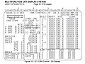 This display screen was used for operational control of the CBM during ISS assembly to stage 3A (STS-92). The image source contains detailed descriptions for each available berthing command and interprets each reportable status message.
 -
 Connections to be made while outfitting the vestibule between Node 1 (Unity) and the US Lab (Destiny). The image source contains a detailed description of the outfitting procedure.
 -
 Vestibule jumpers, such as those shown here between Node 2 and the Columbus module, typically span between well-aligned connectors on facing bulkheads. See the discussion about routing in Link & Williams (2009).
 -
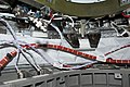 Jumpers in the vestibule between Nodes 1 and 3 are not well aligned because of revisions to the ISS design shortly before Node 3 was delivered to orbit. Node 1 utilities were re-routed by ISS Expedition 21 crew members between STS-129 and STS-130. See the detailed discussion in Link & Williams (2009).
 -
 Mikhail Tyurin of Rosaviakosmos, Expedition 3 flight engineer, secures a connection on a Controller Power Assembly (CPA) in a hatchway on Unity Node 1.
 -
 Astronaut Peggy Whitson, Expedition 16 commander, works in the vestibule between the Harmony node and Destiny laboratory of the International Space Station.
 -
 Anchored by their toes, Expedition 47 Commander Tim Kopra and Flight Engineer Tim Peake wrestle an M/D Cover Center Section into the vestibule while preparing for deberth of a Cygnus cargo vehicle from Node 1 (Unity).
 -
 Posed in a soon-to-be-demated vestibule, Expedition 21 Flight Engineer Nicole Stott provides a sense of scale for both the CBM and the Common Hatch.
 -
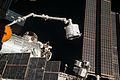 BEAM in the process of being moved to the rear port of Tranquility in April 2016.
 -
 Expedition 5 Flight Engineer Peggy A. Whitson demonstrates proper form for floating through a fully outfitted vestibule.
 -
 The size of the CBM enabled construction of the ISS to defer installation of rack-sized packages until after launch of the modules. Deferral enabled the program's adjustment to changes in orbital inclination, accommodating impacts to the payload capability of the Shuttle.


-
Relocation of PMM "Leonardo" by the SSRMS.
-
The SSRMS grapples the free-flying CRS-12 module and maneuvers it to the ISS for berthing
Missions edit
Uses of the CBM (as of May 2020) are tabulated below. Timing for the factory mates of PMA-1 and PMA-2 to Node 1 are approximate. See Reference to the ISS (Utilization) (NASA/ISSP, 2015) for berths through April, 2015; additional information is available for the Shuttle flights as noted in the PCBM Element column. Later berths are substantiated in the Notes column, as are anomalies and relevant information in NASA flight status reports and other documentation.
| Berth | PCBM Element | Time Frame | Purpose | ACBM Element | Orientation | Notes |
|---|---|---|---|---|---|---|
| 1 | PMA-1 | 09/1998 | Assembly | Node 1 | Aft | Factory Mate |
| 2 | PMA-2 | 09/1998 | Assembly | Node 1 | Forward | Factory Mate |
| 3 | Z1 | 10/2000 | Assembly | Node 1 | Zenith | |
| 4 | PMA-3 | 10/2000 | Assembly | Node 1 | Nadir | |
| 5 | PMA-2 | 02/2001 | Assembly | US Lab | Forward | |
| 6 | U.S. Lab (Destiny) | 02/2001 | Assembly | Node 1 | Forward | |
| 7 | PMA-3 | 03/2001 | Assembly | Node 1 | Port | |
| 8 | MPLM (STS-102) | 03/2001 | Logistics | Node 1 | Nadir | |
| 9 | MPLM (STS-100) | 04/2001 | Logistics | Node 1 | Nadir | |
| 10 | Airlock (Quest) | 06/2001 | Assembly | Node 1 | Starboard | |
| 11 | MPLM (STS-105) | 08/2001 | Logistics | Node 1 | Nadir | |
| 12 | MPLM (STS-108) | 12/2001 | Logistics | Node 1 | Nadir | |
| 13 | MPLM (STS-111) | 06/2002 | Logistics | Node 1 | Nadir | |
| 14 | MPLM (STS-114) | 07/2005 | Logistics | Node 1 | Nadir | |
| 15 | MPLM (STS-121) | 06/2006 | Logistics | Node 1 | Nadir | |
| 16 | PMA-3 | 08/2007 | Assembly | Node 1 | Nadir | Intermittent faults while unbolting. On-Orbit Status Archive (NASA/HQ, 2007),p. 816 |
| 17 | Node 2 (Harmony) | 10/2007 | Assembly | Node 1 | Port | Bolt 1–4 remained failed since PMA-3 demate. Problem believed to be a small, linear negative shift in the load cell. No change to commands. STS-120/FD04 Execute Pkg. (NASA/MCC, 2007) |
| 18 | PMA-2 | 11/2007 | Assembly | Node 2 | Starboard | |
| 19 | Node 2 (Harmony) + PMA-2 | 11/2007 | Assembly | US Lab | Forward | |
| 20 | European Research Laboratory (Columbus) | 02/2008 | Assembly | Node 2 | Starboard | FOD reported on Node 2 Starboard ACBM ring surface; EVA cleaning process established. STS-122/FD05 Execute Pkg. (NASA/MCC, 2008) |
| 21 | ELM-PS | 03/2008 | Assembly | Node 2 | Zenith | |
| 22 | Japanese Experiment Module (Kibo) | 05/2008 | Assembly | Node 2 | Port | |
| 23 | ELM-PS | 05/2008 | Assembly | JEM | Zenith | |
| 24 | MPLM (STS-126) | 11/2008 | Logistics | Node 2 | Nadir | |
| 25 | PMA-3 | 08/2009 | Assembly | Node 1 | Port | |
| 26 | MPLM (STS-128) | 08/2009 | Logistics | Node 2 | Nadir | Bolt 4-1, Node 2 Nadir: high torque on berth, jammed on deberth (replaced IVA); Load cell drift noted on bolt 2-1; Previous incidence of damage to CPA connectors reported. STS-128/FD10 Execute Pkg. (NASA/MCC, 2009), STS-128/FD11 Execute Pkg. (NASA/MCC, 2009) |
| 27 | ISS-HTV1 | 09/2009 | Logistics | Node 2 | Nadir | |
| 28 | PMA-3 | 01/2010 | Assembly | Node 2 | Zenith | Multiple bolt jams during Cupola deberth.Operating an Outpost (Dempsey, 2018) |
| 29 | Node 3 (Tranquility) + Cupola (STS-130) | 02/2010 | Assembly | Node 1 | Port | |
| 30 | PMA-3 | 02/2010 | Assembly | Node 3 | Port | |
| 31 | Cupola | 02/2010 | Assembly | Node 3 | Nadir | |
| 32 | MPLM (STS-131) | 04/2010 | Logistics | Node 2 | Nadir | |
| 33 | ISS-HTV2 | 01/2011 | Logistics | Node 2 | Nadir | OOS – 01/27/11 (NASA/HQ, 2011) |
| 34 | PMM | 02/2011 | Assembly | Node 1 | Nadir | |
| 35 | MPLM (STS-135) | 07/2011 | Logistics | Node 2 | Nadir | |
| 36 | ISS-SpX-D | 05/2012 | Logistics | Node 1 | Nadir | |
| 37 | ISS-HTV3 | 07/2012 | Logistics | Node 2 | Nadir | |
| 38 | ISS-SpX-1 | 10/2012 | Logistics | Node 2 | Nadir | |
| 39 | ISS-SpX-2 | 03/2013 | Logistics | Node 2 | Nadir | |
| 40 | ISS-HTV4 | 08/2013 | Logistics | Node 2 | Nadir | |
| 41 | ISS-Orb-D1 | 09/2013 | Logistics | Node 2 | Nadir | |
| 42 | ISS-Orb-1 | 01/2014 | Logistics | Node 2 | Nadir | |
| 43 | ISS-SpX-3 | 04/2014 | Logistics | Node 2 | Nadir | Only 15 of 16 bolts. 16th bolt was binding. DSR – 04/20/14 (NASA/HQ, 2014) |
| 44 | ISS-Orb-2 | 07/2014 | Logistics | Node 2 | Nadir | |
| 45 | ISS-SpX-4 | 09/2014 | Logistics | Node 2 | Nadir | |
| 46 | ISS-SpX-5 | 01/2015 | Logistics | Node 2 | Nadir | DSR – 01/12/15 (NASA/HQ, 2015) |
| 47 | ISS-SpX-6 | 04/2015 | Logistics | Node 2 | Nadir | DSR – 04/17/15 (NASA/HQ, 2015) |
| 48 | HTV-5 | 08/2015 | Logistics | Node 2 | Nadir | DSR – 08/24/15 (NASA/HQ, 2015) |
| 49 | OA-4 | 12/2015 | Logistics | Node 1 | Nadir | DSR – 12/09/15 (NASA/HQ, 2015) |
| 50 | OA-6 | 03/2016 | Logistics | Node 1 | Nadir | DSR – 03/28/16 (NASA/HQ, 2016) |
| 51 | ISS-SpX-8 | 04/2016 | Logistics | Node 2 | Nadir | DSR – 04/18/16 (NASA/HQ, 2016) |
| 52 | BEAM | 04/2016 | Assembly | Node 3 | Aft | DSR – 04/18/16 (NASA/HQ, 2016) |
| 53 | ISS-SpX-9 | 07/2016 | Logistics | Node 2 | Nadir | DSR – 07/20/16 (NASA/HQ, 2016) |
| 54 | OA-5 | 10/2016 | Logistics | Node 1 | Nadir | DSR – 10/23/2016 (NASA/HQ, 2016) |
| 55 | HTV-6 | 12/2016 | Logistics | Node 2 | Nadir | DSR – 12/13/2016 (NASA/HQ, 2016) |
| 56 | ISS-SpX-10 | 02/2017 | Logistics | Node 2 | Nadir | DSR – 2/23/2017 (NASA/HQ, 2017) |
| 57 | PMA-3 | 03/2017 | Assembly | Node 2 | Zenith | DSR – 3/27/2017 (NASA/HQ, 2017) |
| 58 | OA-7 | 04/2017 | Logistics | Node 1 | Nadir | DSR – 4/24/2017 (NASA/HQ, 2017) |
| 59 | ISS-SpX-11 | 06/2017 | Logistics | Node 2 | Nadir | DSR – 6/05/2017 (NASA/HQ, 2017). ACBM ring face was cleaned by EVA the previous March. DSR – 3/30/2017 (NASA/HQ, 2017) |
| 60 | ISS-SpX-12 | 08/2017 | Logistics | Node 2 | Nadir | DSR – 8/16/2017 (NASA/HQ, 2017) |
| 61 | OA-8E | 11/2017 | Logistics | Node 1 | Nadir | DSR – 11/14/2017 (NASA/HQ, 2017) |
| 62 | ISS-SpX-13 | 12/2017 | Logistics | Node 2 | Nadir | DSR – 12/17/2017 (NASA/HQ, 2017) |
| 63 | ISS-SpX-14 | 04/2018 | Logistics | Node 2 | Nadir | DSR – 4/04/2018 (NASA/HQ, 2018) |
| 64 | OA-9E | 05/2018 | Logistics | Node 1 | Nadir | DSR – 5/24/2018 (NASA/HQ, 2018) |
| 65 | ISS-SpX-15 | 06/2018 | Logistics | Node 2 | Nadir | DSR – 7/02/2018 (NASA/HQ, 2018) |
| 66 | HTV-7 | 09/2018 | Logistics | Node 2 | Nadir | DSR – 9/27/2018 (NASA/HQ, 2018) |
| 67 | ISS-SpX-16 | 12/2018 | Logistics | Node 2 | Nadir | DSR – 12/08/2018 (NASA/HQ, 2018) |
| 68 | CRS NG-11 | 04/2019 | Logistics | Node 1 | Nadir | DSR – 04/19/2019 (NASA/HQ, 2019). ACBM ring face was cleaned by EVA the previous March. DSR – 03/22/2019 (NASA/HQ, 2019) |
| 69 | ISS-SpX-17 | 05/2019 | Logistics | Node 2 | Nadir | DSR – 05/06/2019 (NASA/HQ, 2019) |
| 70 | ISS-SpX-18 | 07/2019 | Logistics | Node 2 | Nadir | DSR – 07/28/2019 (NASA/HQ, 2019) |
| 71 | HTV-8 | 09/2019 | Logistics | Node 2 | Nadir | ISS Status – 09/28/2019 (NASA/HQ, 2019) |
| 72 | CRS NG-12 | 11/2019 | Logistics | Node 1 | Nadir | DSR – 11/04/2019 (NASA/HQ, 2019). |
| 73 | ISS-SpX-19 | 12/2019 | Logistics | Node 2 | Nadir | DSR – 12/08/2019 (NASA/HQ, 2019) |
| 74 | CRS NG-13 | 02/2020 | Logistics | Node 1 | Nadir | DSR – 02/18/2020 (NASA/HQ, 2020) |
| 75 | ISS-SpX-20 | 3/2020 | Logistics | Node 2 | Nadir | DSR – 03/09/2020 (NASA/HQ, 2020) |
| 76 | HTV-9 | 05/2020 | Logistics | Node 2 | Nadir | ISS Status – 05/25/2020 (NASA/HQ, 2020) |
| 77 | CRS NG-14 | 10/2020 | Logistics | Node 1 | Nadir | ISS Status – 10/05/2020 (NASA/HQ, 2020) |
| 78 | Bishop NRAL | 12/2020 | NRAL Ops | Node 3 | Port | ISS Status – 12/21/2020 (NASA/HQ, 2020). Initial delivery to orbit. |
| 79 | CRS NG-15 | 02/2021 | Logistics | Node 1 | Nadir | ISS Status – 02/22/2021 (NASA/HQ, 2021) |
Glossary edit
Many terms used in the CBM literature are not always consistent with usage in other contexts. Some were defined specific to the development program. Definitions are included here to improve continuity with the references, and with other topics.
- Acceptance
- "A process which demonstrates that an item was manufactured as designed with adequate workmanship, performs in accordance with specification requirements, and is acceptable for delivery." Contrast with Qualification. See the Environmental Test Requirements (NASA/ISSP, 2003) page 10-1.
- Analysis
- In the formal context, verification by technical or mathematical models or simulation, algorithms, charts, or circuit diagrams, and representative data. Contrast with Demonstration, Inspection and Test. See the ACBM Dev. Spec. (BD&SG, 1998) §4.2.1.2.
- androgynous
- A characteristic of connectors in which both sides are the same; that is, no "differences of gender" can be assigned. Contrast with Non-androgynous. See also Spacecraft docking and berthing mechanism.
- Assembly
- Specific arrangement of two or more attached parts. When used in the context of a CBM specification, a CBM "half" (either the entire ACBM, or the entire PCBM). See the CMAN Requirements (NASA/ISSP, 2000) §B.2.
- berthing
- A method for structurally joining ("mating") two entities on orbit, e.g., for assembly or retrieval-for-maintenance operations. One or both of the items might be spacecraft operating under independent control authority prior to the mating event. No universally agreed-upon conceptual definition appears to exist. In the context of CBM, the definitive distinctions are found in the ACBM Dev. Spec. (BD&SG, 1998) §6.3:
- a) Providing data to support positioning an ACBM (sic) and its attached element within the capture capabilities of the ACBM
- b) Capture a positioned PCBM and its attached element
- c) Rigidizing the interface with the captured PCBM.
- catastrophic hazard
- Any hazard which may cause permanent disabling or fatal personnel injury of loss of one of the following: the launch or servicing vehicle, SSMB, or major ground facility. See the ACBM Dev. Spec. (BD&SG, 1998) §6.3.
- chase vehicle
- In a docking maneuver, the vehicle that is approaching, usually under active maneuver control. See the usage throughout History of Space Shuttle Rendezvous (Goodman, 2011). Use of the term for the berthing process is inconsistent. In many analyses, it simply refers to the element equipped with the PCBM. Contrast with target vehicle.
- Component
- In the context of the Environmental Test Requirements (NASA/ISSP, 2003) §10.2: "A component is an assembly of parts that constitute a functional article viewed as an entity for purposes of analysis, manufacturing, maintenance, or record keeping; the smallest entity specified for a distributed system. Examples are hydraulic actuators, valves, batteries, electrical harnesses, individual electronic assemblies, and Orbital Replaceable Units."
- Demonstration
- In the formal context, verification by operation, adjustment or reconfiguration of items performing their designed functions under specific scenarios. The items may be instrumented and quantitive limits or performance monitored, but only check sheets rather than actual performance data are required to be recorded. Contrast with Analysis, Inspection and Test. See the ACBM Dev. Spec. (BD&SG, 1998) §4.2.1.3.
- docking
- A method for structurally joining ("mating") two entities on orbit, e.g., for assembly or retrieval-for-maintenance operations. One or both of the items might be spacecraft operating under independent control authority prior to the mating event. No universally agreed-upon conceptual definition appears to exist, but most implementations include using the relative kinetic energy of the chase vehicle to actuate latches that effect the mate. In the context of CBM, limitations on the final relative velocity eliminate docking as an acceptable means of meeting the requirements. See ACBM Dev. Spec. (BD&SG, 1998) §3.2.1.2.2 (which levies requirements on relative velocities of the PCBM with respect to the ACBM at capture) and Spacecraft docking and berthing mechanism.
- EVA (Extravehicular Activity)
- See Extravehicular Activity.
- Execute Package
- An “execute” package consists of flight plans, short-term plans, procedure updates, data needed to operate the space-shuttle and ISS systems, in-flight maintenance procedures, inventory-stowage data, software upgrades, flight notes, scripts for publicized events, and other instructions. See Whitney, Melendrez & Hadlock (2010) page 40.
- flange conformance
- Conformance loads are those applied to eliminate relative deflections across a joint as it is bolted. They result from the stiffness of the joint's members and supporting structure (e.g., a bulkhead). The CBM literature sometimes uses the term "compliance" as a synonym. See the definition for stiffness in the Fracture Control Requirements (NASA/SSPO 2001) page B-6 and Illi (1992) page 5 (pdf pagination).
- Inspection
- In the formal context, verification by visual examination of the item, or reviewing descriptive documentation, and comparing the appropriate characteristics with predetermined standards to determine conformance to requirements without the use of special laboratory equipment or procedures. Contrast with Analysis, Demonstration and Test. See the ACBM Dev. Spec. (BD&SG, 1998) §4.2.1.1.
- IVA (Intravehicular Activity)
- Work done without a pressurized suit inside a spacecraft that is internally pressurized to something like the atmosphere found at sea level. Often referred to as occurring in a "shirt-sleeve environment". Contrast with EVA.
- module
- The precise definition of this term on ISS depends on context. It is used generically for any pre-integrated unit being attached to the on-orbit ISS. When used in the CBM literature, it is a shortened version of "pressurized module", synonymous with "Pressurized Element (PE)". Many sources appear to use all of these terms interchangeably. In the context of CBM, it includes things that cannot be pressurized before berthing, but can contain pressure after berthing is complete (e.g., Cupola, Pressurized Mating Adapters).
- Moving Mechanical Assembly
- A mechanical or electromechanical device that controls the movement of one mechanical part of a vehicle relative to another part. See the Environmental Test Requirements (NASA/ISSP, 2003) page 10-3.
- non-androgynous
- A characteristic of connectors in which one side is different that the other. Such connectors are often described as "gendered". The concept is sometimes referred to as "heterogenous". Contrast with Androgynous. See also Spacecraft docking and berthing mechanism.
- NRAL (NanoRacks Airlock)
- NRAL is an abbreviation sometimes used in the NASA Status Reports in lieu of the element's formal nomenclature (NanoRacks Bishop Airlock).
- preloaded joint
- As used in the Space Station program, a preloaded joint is one in which the clamping force is sufficient to a) provide for life due to cyclic loads; b) to assure that the joint stiffness doesn't change due to flange separation; and c) to assure that pressure seals (if present) are not affected by flange separation. “Pre” is used in the sense of being present when the joint is first made, before being exposed to service loads. The clamping force is typically provided by a bolt, but can be supplied by other types of mechanical device. See the Structural Design Requirements (NASA/SSPO, 2000) page B-5.
- pressure decay test
- A known volume of pressurized gas permeates through and/or leaks at the interface of a seal under test while the pressure and temperature are recorded over time. Although this method is low cost and applicable to an extensive range of leak rates, it has several limitations that "reduce feasibility": see Oravec, Daniels & Mather (2017) pp 1–2.
- pressure vessel
- A container designed primarily for pressurized storage of gases or liquids that meets certain criteria for stored energy or pressure. See the Structural Design Requirements (NASA/SSPO, 2000).
- Pressurized Element
- See module.
- pressurized structure
- A structure designed to carry vehicle loads in which pressure is a significant contributor to the design loads. See the Structural Design Requirements (NASA/SSPO, 2000) Appendix B.
- port
- Not used in a consistent manner. In some sources, a combination of penetrated primary structural bulkhead (sealed with a hatch) and a CBM. In other sources, anywhere a CBM is used (with, or without, a bulkhead and hatch).
- PDRS (Payload Deployment and Retrieval System)
- The collection of Shuttle subsystems and components used to hold and manipulate items in the payload bay, especially items for which flight release (or mating) was planned. Elements included the Shuttle RMS, Payload Retention Latch Assemblies, Grapple Fixtures, Targets, and a CCTV system. See the Payload Bay User's Guide (NASA/NSTS, 2011).
- Primary Structure
- That part of a flight vehicle or element which sustains the significant applied loads and provides main load paths for distributing reactions of applied loads. Also the main structure which is required to sustain the significant applied loads, including pressure and thermal loads, and which if it fails creates a catastrophic hazard. See the ACBM Dev. Spec. (BD&SG, 1998) §6.3 and the Structural Design Requirements (NASA/SSPO, 2000) Appendix B.
- Proximity Operations
- Operations by one (or more) independently controlled spacecraft within 2,000 feet (610 m) of another, characterized by nearly continuous trajectory control. See the usage throughout History of Space Shuttle Rendezvous (Goodman, 2011). Contrast with rendezvous control.
- Qualification
- "Qualification is the process that proves the design, manufacturing, and assembly of the hardware and software complies with the design requirements when subjected to environmental conditions." Contrast with Acceptance. See the Environmental Test Requirements (NASA/ISSP, 2003) page 10-5.
- Reaction Control System (RCS)
- A type of Attitude Control System (ACS). RCS is distinguished by active implementation of Newton's Second Law to manage the orientation of a spacecraft without changing the orbital parameters of the center of mass. Propulsive RCS can, if so designed, also be used for Orbital Maneuvering (implementing Kepler's Laws to changing the spacecraft's orbital parameters). See Kaplan (1976) p. 2 and Chapters 3–4.
- Rendezvous
- Maneuvers by one spacecraft to match the orbital parameters of another. These maneuvers place the two spacecraft in such close proximity that the mathematics of “orbital mechanics” no longer dominate the ability to bring them closer still. These operations are typically executed by one independently controlled spacecraft at ranges greater than 2,000 feet (610 m) of another. They can be characterized by trajectory control maneuvers occurring at intervals of tens of minutes or greater. See the usage throughout History of Space Shuttle Rendezvous (Goodman, 2011). Contrast with proximity operations.
- RMS (Remote Manipulator System)
- A tele-robotic device used to maneuver payloads in the near vicinity of a spacecraft (comparable in range to the terminal operations of docking). Several examples exist: those relevant to CBM documentation are the Shuttle RMS (SRMS) and the Space Station RMS (SSRM). The two are colloquially known as "Canadarm" and Canadarm2, respectively, but the documentation almost exclusively uses the nomenclature shown here.
- subassembly
- With respect to some reference assembly, an assembly which is wholly contained within the reference assembly. In the context of the CBM, a mechanism for which verification activities can take place ex situ. The definition here follows the CMAN Requirements (NASA/ISSP, 2000), §B.2, but see the Environmental Test Requirements (NASA/ISSP, 2003) §10.2 for nuances of application.
- Target Vehicle
- In a docking maneuver, the vehicle being approached. The target vehicle is sometimes under active attitude control, but not typically under active maneuver control. See the usage throughout History of Space Shuttle Rendezvous (Goodman, 2011). The term is inconsistently found in the technical literature with regard to berthing. In many CBM analyses, the term refers to the element equipped with the ACBM. Contrast with chase vehicle.
- Test
- In the formal context, verification through systematic exercising of the item under all appropriate conditions. Performance is quantitatively measured either during or after the controlled application of either real or simulated functional or environmental stimuli. The analysis of data derived from a test is an integral part of the test and may involve automated data reduction to produce the necessary results. Contrast with Analysis, Demonstration and Inspection. See the ACBM Dev. Spec. (BD&SG, 1998) §4.2.1.4.
- Thermal Mass
- In thermal analysis, a synonym of “capacitance”, which is analogous to its usage in electrical network analysis. Thermal mass can be achieved either by literal large mass, or by a large heat storage capacity of a material (e.g., one that changes phase at near-constant temperature). See Gilmore (1994) page 5-24.
See also edit
Notes and citations edit
- ^ a b c d e The length shown is for the mated vestibule. See the Design Gallery for the lengths of the individual sides. Both sides have the same diameter. PCBM specified mass: see PCBM Dev. Spec. (BD&SG, 1998) §3.2.2.3. ACBM specified masses: see ACBM Dev. Spec. (BD&SG, 1998) §3.2.2.2. Masses shown are "as specified"; very few weights were reported in the literature, none of which indicated any particular complement of hardware. The as-flown mass may differ from the specified value. See the Operations Gallery for the dates of operation and number of missions. The Developers shown are based on the signature pages for the specifications. The PCBM appears to have been manufactured by more than one source, but a comprehensive assessment was not conducted.
- ^ Ring material: Illi (1992). Silicone temperature performance:O-Ring HDBK (PHC, 2018) page 2-5. Fluorocarbon wear performance: Christensen, et al. (1999) page 5.
- ^ ACBM Dev. Spec. (BD&SG, 1998) §3.3.
- ^ a b c d e The geometry of the interfacing features on the rings (both ACBM and PCBM) is extensively documented in the CBM/PE ICD (NASA/ISSP, 2005). For example, the o-ring groove geometry where the rings mount is shown in Figures 3.1.4.2–3 and −4 and Figure 3.3.2.1–7, and ACBM/PE interface scallop is dimensioned in Figure 3.1.4.2 – 5 and −6. 4A Maintenance Book (NASA/MOD, 2000), §§1.2.518 – 520 contains the detailed installation steps and additional photographs of the IVA Seal and related hardware.
- ^ Vestibule closeout panel interfaces: CBM/PE ICD (NASA/ISSP, 2005) §3.3.8. On-orbit module-to-module jumper envelope: ICD §3.1.4.
- ^ a b c d e f g h i j k l m n o p q r s t u v w x y z aa ab ac ad ae af ag ah ai aj ak al am an ao ap aq ar as at au av aw ax ay az ba bb Part identifications and nomenclatures are generally as found in Foster, Cook, Smudde & Henry (2004), Figure 3, which is identical to Figure 2-1 of the Assembly Qual. Test Report (BD&SG, 1998). In both cases, the figures address only those components found in the PCBM and the Type I ACBM as used on axial ports. They omit identification of the CBM/CBM and CBM/PE IVA seals and all ancillary equipment. They also omit identification of bumpers that are installed on radial port ACBM and of the corresponding feature on the PCBM (variously referred to in the literature as "bumper" or "follower"). Many parts are also identified throughout the CBM/PE ICD (NASA/ISSP, 2005) and in Appendix A of the Assembly Qual. Test Report (BD&SG, 1998), although the nomenclatures are sometimes different than in the other two references. See the talk (discussion) page on each original image upload for additional source referencing.
- ^ CBM functionality is inconsistently described in the literature. It is unclear whether the apparent discrepancies resulted from evolution of the design over the project's life, or from the perspectives of different authors. Compare Illi (1992) p. 282, Winch & Gonzalez-Vallejo (1992) p. 67, Searle (1993) pp. 351–352, ACBM Dev. Spec. (BD&SG, 1998) §3.3.1 and §6.3 (which are themselves not completely consistent), PCBM Dev. Spec. (BD&SG, 1998) §§3.1.2–3.1.3, the nominal test flow of §2.6.3 in the Assembly Qual. Test Report (BD&SG, 1998), the operational sequence on p. 39 of Operating an Outpost (Dempsey, 2018), Pilot and Mission Specialist 2 timelines on pp. 6–7, 12–13 (pdf pagination) of STS-120/FD04 Execute Pkg. (NASA/MCC, 2007), the detailed steps described on pp 200–203 of the 3A Assembly Ops (NASA/MOD, 2000), and procedures defined for Stage 5A on pp. 23–97 of the 5A Assembly Ops (NASA/MOD, 2000). The present description merges the two descriptions found in the development specification.
- ^ Some authors (e.g., Winch & Gonzalez-Vallejo (1992), Foster, Cook, Smudde & Henry (2004)) appear to treat alignment as a "function" actively performed by the ACBM. Others (e.g., Operating an Outpost (Dempsey, 2018)) discuss it more as a "physical characteristic" constituting a constraint imposed by the ACBM. No obvious resolution to the difference in perspective appears to be available in the literature.
- ^ Foster, Cook, Smudde & Henry (2004) (p. 303) and Cook, Aksamentov, Hoffman & Bruner (2011) p. 27 (pdf pagination) both describe the ACBM as having two sets of alignment structures: Coarse Alignment Guides and Fine Alignment Pins. The Assembly Qual. Test Report (BD&SG, 1998), Appendix B explicitly identifies "bumpers" as part of the as-qualified test articles, but does not show them in Figure 2-1 of that report (identical to Figure 3 of Foster, Cook, Smudde & Henry (2004)). The report discusses the bumpers as a preliminary stage of alignment, and §3 of the CBM/PE ICD (NASA/ISSP, 2005) conclusively identifies them as part of the ACBM for Radial Ports (referring to them as "the new bumper" in note 4 of Figure 3.1.4–9). The RTL/Capture Envelope survey identifies 25 cases (of 124 surveyed) where the bumpers constrain motion in certain directions before any other contact surface is reached; that is, a stage of alignment before the Coarse Alignment Guides. All bumper contacts are at or above 3.75" of axial separation between the two rings, suggesting that Alignment Guides do not become the overriding constraint until around that separation. No obvious resolution was found for this apparent disconnect in the number of alignment stages within and between sources.
- ^ The trajectory envelope of the PCBM with respect to the ACBM ("combined rotation and translation") is shown by the trajectory plots in Appendices E and F of the Assembly Qual. Test Report (BD&SG, 1998). Many trajectories are non-monotonic, with rotations that actually increase for a few seconds after capture latch loads first begin to build. In a few cases, translations also increase. In all cases, however, the trajectories end with the PCBM being aligned to, and slightly separated from, the ACBM.
- ^ ACBM Dev. Spec. (BD&SG, 1998) §3.1. The ACBM Spec. is identified by Foster, Cook, Smudde & Henry (2004) page 303 (footnote 3). The PCBM Dev. Spec. (BD&SG, 1998) is identified as Reference 2 of Christensen, et al. (1999) (pdf page 6). The two specifications contain a large number of requirements in common. In order to mitigate the number of references, only one of the two specifications is typically cited herein. Cases in which the reference explicitly cited is applicable to just one of the two Configuration Items are plain from the content and context of their reference.
- ^ In ("forward") or opposite ("aft") the direction of orbital travel, toward ("nadir") or away from ("zenith") the orbit's center, below ("port") or above ("starboard") the orbital plane when facing forward with feet to nadir. See Operating an Outpost (Dempsey, 2018), page xv (17 in the pdf pagination).
- ^ a b The orientations at which an ACBM can be installed are found in the CBM/PE ICD (NASA/ISSP, 2005) §3.3.2.1.4. Qualification temperatures are from the Environmental Test Requirements (NASA/ISSP, 2003) (SSP 41172), pages 424 and 425 (pdf pagination). They are also addressed in Miskovish, et al. (2017) slide 5. There appear to be discrepancies between and within the published sources. SSP 41172 identifies a qualification temperature range for the bolt and nut (−50F – +150F) that is smaller than the range it references for their usage in the Assembly Qualification Test (−70F – +190F), which is inconsistent with the practices for component-level testing in the same document. The range depicted in Miskovish is substantially less than that quoted in SSP 41172. Figure 6 of the ACBM Dev. Spec. (BD&SG, 1998) identifies Miskovish's depicted range as being applicable for "boltup". The specification further requires ranges of temperature differential of −170F to +170F for nut acquisition and −200F – +200F for capture (both on absolute ranges of −70F – +170F). No reconciliation of the discrepancies is obvious in the available sources.
- ^ ACBM Dev. Spec. (BD&SG, 1998) §3.1.
- ^ Foster, Cook, Smudde & Henry (2004) explicitly refers to the PCBM's thermal standoffs as mechanisms, and to the Powered Bolt Nut as "floating" (that is, a mechanism). The nut design was qualified for vibration, thermal vacuum conditions, and life cycle (durability) as a stand-alone assembly. See the CBM Bolt/Nut Qual. Test Report (BD&SG, 1998) Table 1-1 (p. 1–7), which aligns well with requirements in the Environmental Test Requirements (NASA/ISSP, 2003) §4.2.13.
- ^ Regarding "push-off": PCBM Dev. Spec. (BD&SG, 1998) §3.2.1.6: "..shall provide the net force and moment...for separation of the elements during deberthing." §4.3.2.1.6 identifies seal "stiction" and RMS resistance as factors to be verified in this regard. Seal "stiction" (adhesion) can be substantial. Sub-scale testing reported in Daniels, et al. (2007) (pdf page 15) estimated adhesion during release of CBM-type elastomeric seals from their faying surface at about 150 lbf (670 N) for a 12 in (30 cm) diameter, single-bead test specimen seal. Regarding stabilization, see Foster, Cook, Smudde & Henry (2004) at the top of page 304.
- ^ Christensen, et al. (1999) p. 196.
- ^ PCBM Dev. Spec. (BD&SG, 1998) §3.2.1.8.2. See also Operating an Outpost (Dempsey, 2018), Figure 2 (p. 37) and File:PMA3 Mounted in SLP.jpg.
- ^ The bulkhead is often referred to in the literature as a "berthing plate". Cupola and the three PMA's have no bulkhead to hold pressure when unberthed.
- ^ a b The PCBM Dev. Spec. (BD&SG, 1998) Figure 6 requires accommodation of pre-berth temperature differentials of +/- 200F between the two outboard flanges when Capture Latches are actuated, +/-170F for acquisition of Powered Bolt Nuts, and −70F to +90F when the interface is rigidized.
- ^ Shower cap removal: STS-120 EVA Cklist (NASA/MOD, 2007), pdf pp. 130 and 254 (photo). Launch lock removal: STS-123 EVA Cklist (NASA/MOD, 2008) (pdf page 131). Launch locks can also be removed by driving a Powered Bolt (pdf p. 312, step 2.6.D, note 2). Times vary because other activities were accomplished around some of the ports. All ACBM launches to date occurred during the NSTS era.
- ^ a b The ISS/Shuttle Joint Ops. (LF1) (NASA/MOD, 2005), pdf pp. 523 – 527 discusses detailed inspection criteria for both the ACBM and PCBM, including post-landing photographs of Foreign Object Damage (FOD) found on the PCBM's Gask-O-Seal after UF-2 (STS-114).
- ^ Provisioning of tools to clean the PCBM seals is referred to in the EVA workarounds cribsheet on pdf page 177 of the STS-122 EVA Cklist (NASA/MOD, 2007).
- ^ Task time and description: STS-123 EVA Cklist (NASA/MOD, 2008), pdf pages 56, 70.
- ^ Preparation for mating operations begins on p. 82 (pdf pagination) of the 5A Assembly Ops (NASA/MOD, 2000). These steps can be executed by either flight or ground crew. Several other examples exist from as early as Stage 3A in documentation available online. Description of the pre-berthing Bolt Actuator test ("BBOLTCK") is from the 3A Assembly Ops (NASA/MOD, 2000), p. 210 (pdf pagination), which contains detailed descriptions for many other CBM commands.
- ^ Cleaning the ACBM sealing surface: STS-122/FD05 Execute Pkg. (NASA/MCC, 2008), pp. 2, 27 and DSR – 3/30/2017 (NASA/HQ, 2017). EVA access to CBM components, and the removal and replacement thereof, is addressed in detail on pp. 224–260 (pdf) of the STS-124 EVA Cklist (NASA/MOD, 2008). "Prep for Mate" CPA malfunctions are found in pp. 26–88 (pdf) of the 5A Assembly Malfunctions (NASA/MOD, 2000).
- ^ The operational flow is summarized from Operating an Outpost (Dempsey, 2018), page 243. Use of SVS and CBCS visual cue systems, including photographs of the operator's display, are found on pp. 44–45.
- ^ Description of how the Ready-to-Latch Indicators are used is on page 44 of Operating an Outpost (Dempsey, 2018). Three-of-four RTL and the reference to a state that can resist the RTLs (e.g., Position Hold) are from the 5A Assembly Ops (NASA/MOD, 2000) p. 64 (pdf pagination). For an example of choreography, see the video of PMM Leonardo's relocation. Several examples of contingency planning for the maneuver operation are found in the STS-114 PDRS Ops Cklist (NASA/MOD, 2004)
- ^ First-stage capture settings, operational constraints, completion criteria and execution time: pp 64–66 (pdf pagination) of 5A Assembly Ops (NASA/MOD, 2000). Load control might not be required for all CBM operations: see the STS-130/FD09 Execute Pkg. (NASA/MCC, 2010).
- ^ NSTS era second stage capture: p68 of the 5A Assembly Ops (NASA/MOD, 2000). During capture with the SSRMS, it is intermittently operated between capture commands to further alleviate load build up; see the STS-128/FD10 Execute Pkg. (NASA/MCC, 2009) page 24 (pdf pagination). Second stage capture: SRMS into Test Mode, which may cause RTLs to open. Indicated shaft angle when at the end of second-stage capture (about 108 seconds) is from p68 of the 5A Assembly Ops. The RTL position is substantially below the top of the Capture Latch arc: compare the dimensioned side elevation view of the RTL in CBM/PE ICD (NASA/ISSP, 2005) Figure 3.1.4.1–12 to the clear volume elevation shown in Figure 3.1.4.1–17.
- ^ Nominal bolt command descriptions are found in the 3A Assembly Ops (NASA/MOD, 2000), pp.210–211 (pdf). The overall boltup process, including the budgeted time, is described in detail in McLaughlin & Warr (2001) p. 2, and starting on page 73 (pdf) of the 5A Assembly Ops (NASA/MOD, 2000). Page 64 (pdf) of the latter source states that if the "at least eight bolts" are not "alternating", then ground controllers will advise the crew how to proceed. The interpretation of "at least eight bolts" may have been substantively revised by the time STS-128 installed the MPLM; see the caution on page 23 of the STS-128/FD10 Execute Pkg. (NASA/MCC, 2009). ABOLT speed: McLaughlin & Warr (2001) page 2. The sources are not in complete agreement on the nomenclature of the command. It appears as "ABOLT", "ABOLTS", "A Bolt", and "A bolts". Some of the sources are not internally consistent in this regard.
- ^ The CBM Bolt/Nut Qual. Test Report (BD&SG, 1998) p. 3-2 reports the 1,500 lbf (6.67 kN) preload to be the lower end of the toleranced region for performance of the bolt's load cell. The upper end is quoted at 19,300 lbf (85.9 kN).
- ^ Thermal stabilization: McLaughlin & Warr (2001)(page 3) states that the equalization hold occurs at a much higher preload of 10,500 lbf (47,000 N), but the flight documentation reads as described here: see the caution banner on page 109 (pdf) of 5A Assembly Ops (NASA/MOD, 2000). 90° bolt group spacing: 3A Assembly Ops (NASA/MOD, 2000) near the bottom of page 212 (pdf pagination). The detailed bolt loading procedure (up to and including full preload) begins on page 110 (pdf) of the 5A Assembly Ops. Subsequent flights often allocate this task to ground controllers.
- ^ For one- and two-bolt failure capability, see Zipay, et al. (2012) pdf pages 18 and 41, respectively. The reference does not discuss whether pressurized access to the vestibule can somehow be restored after the two-bolt-out scenario occurs. Detailed resolution procedures, including those for rapid safing, are indexed beginning on page 8 in the pdf pagination of the 5A Assembly Malfunctions (NASA/MOD, 2000). Procedures dealing with failures in the capture latch and Ready-to-Latch Indicator are found in pp.21–30 (pdf) of the STS-128/FD04 Execute Pkg. (NASA/MCC, 2009).
- ^ a b c On most ports, the CPAs are completely removed, but the Nadir ports of Nodes 1 and 2 were modified on orbit to rotate the CPAs in place. See DSR – 1/3/2018 (NASA/HQ, 2018).
- ^ Detailed procedures for vestibule outfitting are found in the 5A Assembly Ops (NASA/MOD, 2000), pp. 129 – 171 (pdf pagination). Each vestibule is at least slightly different, and some (e.g., Cupola, PMA) depart significantly from the generic description given here. In many cases, procedures and NASA status reports clearly indicate a pause of about eight hours for a fine leak check, but some of the reported timelines do not appear to accommodate any such operation. The M/D Center Section removal procedure is described in detail starting on page 70 (pdf pagination) of the 5A Joint Ops. (NASA/MOD, 2000), from which the budgeted time was taken, but the 4A Maintenance Book (NASA/MOD, 2000) budgets twice that for removal (pdf page 74).
- ^ Detailed procedures to remove internally accessible CBM components (CPA, Bolt, Nut, Latch, RTL) and install IVA seals are indexed on page 8 in the pdf pagination of 4A Maintenance Book (NASA/MOD, 2000), as are the general procedures for leak pinpointing. Procedures for the alternate CPA installation to preclude damage are found in STS-126/FD13 Execute Pkg. (NASA/MCC, 2008), page 3 (pdf).
- ^ Preparation for demating operations begins on p. 38 (pdf pagination) of the 5A Assembly Ops (NASA/MOD, 2000).
- ^ See the Missions Table for the relative occurrence of logistics flights compared to assembly flights. The details of time budgeting appear to have evolved over time. For vestibule deoutfitting of logistics elements (in this case, MPLM), see the 5A.1 MPLM Book (NASA/MOD, 2000), page 134 (pdf pagination). Allocation of two crewmembers to deoutfitting is based on the STS-102/FD10 Original Plan (NASA/MCC, 2001), which allocated less time for the task. No effort to install the CBCS is accounted for in the current description; an informal sampling of recent status reports suggests that it is not used in support of deberthing operations. The time to reconfigure for demate probably decreased significantly after CPA rotation kits were introduced: installation of four CPAs was budgeted for about 2:30 in the 4A Maintenance Book (NASA/MOD, 2000), page 74 (pdf). M/D Cover Center Section installation is detailed in the 5A Joint Ops. (NASA/MOD, 2000), page 170 (pdf). Ground strap removal steps follow directly thereafter. Removal of the Vestibule Closeout is budgeted for 40 minutes on pdf page 84 of the 4A In-Flight Maintenance Book, but for only 20 minutes in the Joint Operations Book (5A), page 70 (pdf).
- ^ Including installation of pressure test equipment, depressurization was budgeted for about 75 minutes in the STS-102/FD10 Original Plan (NASA/MCC, 2001); the 40-minute duration of actual depressurization comes from summing the dwell periods in the 5A.1 MPLM Book (NASA/MOD, 2000), pages 150–153. That reference omits an overall task duration, which had to have been somewhat longer to allow for crew steps. The STS-102 timeline suggests that depressurization is not included in the deoutfitting task, as does the organization of 5A.1 MPLM Book, but the 4:30 timeline from the start of MPLM egress to the end of CBM demate in same timeline suggests that it might have been. No resolution of the apparent time budgeting discrepancy appeared obvious in the available documentation. The tolerance for the conversion of pressure to metric units is based on the readily-available manual for the Fluke 105B meter identified in the reference (±0.5%). The manual doesn't indicate whether the experimental uncertainty is "indicated" or "full scale"; "full scale" was assumed here. The rationale for the constraint on pressure is from OOS – 01/22/10 (NASA/HQ, 2010): "...it must be ensured that the pressure is below 2mmHg before demating to protect the CBM (Common Berthing Mechanism) seals." The limit itself is in the procedures (e.g., the MPLM Book (5A.1), pdf page 152) but the rationale is not identified therein.
- ^ Activation and checkout of the CBM for deberth can be executed either by ground control or from orbit. The general flow of procedures is from the 3A Ground Handbook (NASA/MOD, 2000) and 5A Assembly Ops (NASA/MOD, 2000). Although the DBBoltck command (distinct from the "BBoltck" command) is explicitly called for in both documents, neither detailed description nor rationale were found that would differentiate it from the BBBoltck command. CBM checkout by the ground and left with CPAs powered on: see STS-114/FD11 Execute Pkg. (NASA/MCC, 2005), pdf page 3.
- ^ The STS-102/FD10 Original Plan (NASA/MCC, 2001) allotted 90 minutes for demate and deactivation of the Node 1 Nadir ACBM. The bolt loosening procedure starts on page 57 (pdf pagination) of the 5A Assembly Ops (NASA/MOD, 2000). A motion range of ±0.1 revolutions is quoted; later editions of the procedure expand the positional tolerance. The CBM Bolt/Nut Qual. Test Report (BD&SG, 1998) p. 3-2 identifies the success criterion for unbolting as relieving the preload with a peak torque not exceeding 1,600 lb⋅in (180,000 mN⋅m); McLaughlin & Warr (2001) identifies a speed limit of 0.5 RPM at that torque on page 4, although page 3 reports that the "F Bolt" command in the opposite direction at full load to be executed at 0.4 RPM. Taken together with overall time allocated by the procedure, this suggests that loosening is actually implemented in sets of four bolts rather than all 16 at once.
- ^ The loosening criterion on 5A Assembly Ops (NASA/MOD, 2000), page 58 (pdf) is consistent with findings reported on page 5-7 of the Assembly Qual. Test Report (BD&SG, 1998): "...if the indicated load on a bolt ever goes below 1500 pounds during extraction, it must be fully extracted not less than 29 turns from full preload without any additional sets being actuated in either direction. There are no exceptions to this rule." The rule is reported by the same source to have resulted from damage incurred during some of the first demates during setup for the Assembly level qualification test sequence, where no such constraint was imposed.
- ^ Bolt extraction, cover closure, and CBM shutdown: 6A Assembly Ops (NASA/MOD, 2001), pages 69–91. Closure of the covers is visually verified by camera image.
- ^ Demate contingency operations are indexed on pp. 8–9 in the pdf pagination of the 5A Assembly Malfunctions (NASA/MOD, 2000). The relative speed of undocking and deberthing is noted on page 41 of Operating an Outpost (Dempsey, 2018).
- ^ For the originally-designed usage of the Nadir port on Node1, see Link & Williams (2009) page 1, which includes a detailed discussion of the engineering changes required to integrate Node 3 in that location. PMA3 was essentially used as a Diving Bell would be used underwater. For a programmatic description of the re-design and implementation, see Operating an Outpost (Dempsey, 2018), page 64-67 of the pdf pagination. For the quoted listing of re-routed utilities, see OOS – 11/20/09 (NASA/HQ, 2009), which does not provide a definition for the ISL connections referred to. The status report's list appears to diverge from the detailed discussion in Link pp. 2–5. Reconciliation of the two discussions was not obvious from the available documentation. The definition of IMV is from Operating an Outpost, page 187.
- ^ See NASA's Space Station Research Slingshot Announcement (NASA/ISSP, 2019).
- ^ a b Foster, Cook, Smudde & Henry (2004) (p. 319 of the pdf pagination) and the Assembly Qual. Test Report (BD&SG, 1998) (ALQTR) (§3.2 "Precursor Developmental Activities") identify the same three critical activities and their associated factors "...establishing the combined conditions under which the CBM must function..." (ALQTR, page 3-2). The two sources clearly refer to the same event (Foster's Figure 4 is identical to the report's Figure 3-3) but they organize their discussion differently and contain some divergent material: the ALQTR reports a fourth chain of logic, having to do with the performance of the Powered Bolt's acquisition of the Nut; Foster refers to "Full-Scale Seal Tests" that are unmentioned in the formal test report. The test also receives summary discussion in Zipay, et al. (2012) (p. 40–41 in the pdf pagination) that is generally consistent with the other two sources, but having less detail.
- ^ a b The loading condition with external loads and without vestibule pressure (that is, as an external flange) is shown in Figure 39 of Zipay, et al. (2012). The condition with both external load and internal (vestibule) pressure is shown in Figure 40 of the same reference.
- ^ The Fracture Control Requirements (NASA/SSPO 2001) and Structural Design Requirements (NASA/SSPO, 2000) detail the program's Engineering practices by which pressure vessels and pressurized structures are qualified for fracture and structural loads, respectively.
- ^ a b Each berth can have a unique RMS joint configuration, and the inertial properties of the modules being berthed vary over a wide range (see the module-by-module summaries in the Reference to the ISS (Utilization) (NASA/ISSP, 2015)). Analysis is used to define loads and predict performance throughout a mechanism's stroke. Test is used to ensure that the internal dynamics are properly modeled under representative loads, which often includes compensation for gravity. The iterative approach is discussed briefly in Conley (1998), p. 589 "Deployment Analysis". See the discussion of "Offloading Systems" (p. 534 in Conley) for a description of how gravitational effects are compensated for during test of spacecraft mechanisms.
- ^ "The conformance loads define the scrubbing action on the seal during boltup..." Assembly Qual. Test Report (BD&SG, 1998) p. 3-5. The manufacturer's recommended maximum gapping after boltup is complete for a Gask-O-Seal is 0.003 inch (Gask-O-Seal Hdbk (PHC, 2010) page 9). The importance of cleanliness of the manufacturing condition for factory-assembled joints is discussed on page 18 of the same reference, and by Holkeboer (1993), pp. 256–257. In contrast, the CBM/CBM is a "field joint", assembled in an uncontrolled environment. The launch environment for early berths of PCBM-equipped elements was the (reused) Shuttle Payload Bay; cleanliness of the payload bay environment is discussed in §§4.1.3.3 and 4.2.3 of the Payload Bay User's Guide (NASA/NSTS, 2011). Since retirement of the Shuttle, all deliveries occur under flight-dedicated payload fairings, each of which may reasonably be expected to have its own characterization.
- ^ Typical orbit altitude: Operating an Outpost (Dempsey, 2018), page 123. This region of Earth orbit is usually referred to as the thermosphere.
- ^ The temperature of the gas starts increasing with altitude in this region, but the density is so low that spacecraft see little heating from the temperature. See Natural Environments (Justh, ed., 2016) §5.1 for a description of the environment, and §5.1.7 for a brief review of Atomic Oxygen's general effect on spacecraft. For the seal's sensitivity, see Christensen, et al. (1999). On the topic of the influence of combined temperature and vacuum on friction, see Conley (1998) pp. 176 and 589, and Chapter 17. For a wide-ranging contemporary survey of friction data under both atmospheric and vacuum conditions, see Lubrication Handbook for the Space Industry (NASA/MSFC, 1985). For a brief discussion of changes in chemical composition due to vacuum exposure ("outgassing") see Conley's Chapter 9.
- ^ Because they deal with radiation, these issues are often referred to as "thermal-optical". See §5.2 of Natural Environments (Justh, ed., 2016) for a description of the thermal environment.
- ^ a b At about 7 feet in diameter, the CBMs encompass between 10 and 20% of a typical Node's surface area. Even though this phenomenon is directional and (therefore) dependent on the orbital parameters, it cannot be ignored during periods where multiple ports are unmated or when ports are unmated for long periods of time in aggressive orientations. See Natural Environments (Justh, ed., 2016), §5.6.4, Chapter 3 of Gilmore (1994) and Conley (1998) Chapter 20 for additional discussion of relevant Operational and Engineering accommodation techniques.
- ^ The magnetic field varies depending on where the spacecraft is in its orbit (the "true anomaly"), so it is usually referred to as "geomagnetic". Relevant characteristics are discussed in §5.3 of Natural Environments (Justh, ed., 2016), along with some of the pertinent spacecraft design issues.
- ^ See §5.4 of Natural Environments (Justh, ed., 2016) for a parametric discussion of the plasma environment at the altitude of ISS. Excess positive charge on the ISS is managed through a Plasma Contactor Unit mounted on the Z1 Truss element. It eliminates arcing between the spacecraft and the charged environment. See Carpenter (2004).
- ^ The thermosphere's ionizing radiation environment is described §5.5 of Natural Environments (Justh, ed., 2016). The effects are generically described in §5.5.3.
- ^ For example, non-quantitative M/D requirements were documented in the ACBM Dev. Spec. (BD&SG, 1998) §3.2.5.12. A recent assessment of Meteoroid/Debris environment is described in Natural Environments (Justh, ed., 2016) §5.6; the reference notes that, although debris is not strictly "natural" in origin, it is treated as such for descriptive purposes because it is outside the control of any development project.
- ^ In this context, "plume" refers to a rocket's exhaust jet after it leaves the nozzle. During proximity operations, a rocket fired by a chase vehicle to slow its approach toward a target is often aimed at that target (a "braking maneuver"). When the exhaust hits the target, it generates forces that can push the target away and, if striking off-center, spin it around. Depending on the composition of the exhaust, the plume can also contaminate the outside of the target vehicle. Regarding the effect of plume impingement on the target vehicle, operations to mitigate them are extensively discussed in Shuttle/LDEF Retrieval Ops (Hall, William M., 1978) starting on page 10 (pdf pagination). Contamination can degrade the target's thermal control and power generation capabilities. See, for example, the discussion of Apollo spacecraft jets interacting with Skylab in History of Space Shuttle Rendezvous (Goodman, 2011), Chapter 5. The shape and density of the plume may not be intuitive. See the discussion starting on p 166 of Griffen & French (1994).
- ^ See Figure 1 of Cook, Aksamentov, Hoffman & Bruner (2011) for a "tree" of assembly mechanisms. The need to assemble large things on orbit is discussed on page 9 of History of Space Shuttle Rendezvous (Goodman, 2011). The same reference notes on page 16 that the emergent concepts were considered too dangerous for the one-person spacecraft of the Mercury program, and were deferred to the larger crew complement of Project Gemini. Mercury did, however, contain flight experimentation on the ability of the pilot to estimate distances and attitudes in space. "Apollo era" is used abstractly here to include Skylab, and the Apollo/Soyuz Test Project. See pages 15 – 59 of the reference for a more comprehensive historical treatment.
- ^ See History of Space Shuttle Rendezvous (Goodman, 2011), page 69 for an introductory discussion of newly encountered circumstances and factors in the Space Shuttle program. The comment on coaxiality is found on page 4 (pdf page 9) of Cohen, Eichold & Heers (ed.) (1987). Shuttle/LDEF Retrieval Ops (Hall, William M., 1978) contains a detailed explanation of the physics and mathematics of the r-bar approach, including an exposition on the relationship between it and use of the SRMS to retrieve free-flying spacecraft. Comprehension of what was known (or expected) in the time frame where berthing was developed can be enhanced by reading it in the context of Livingston (1972) and the RMS Requirements (NASA/JSC,1975).
- ^ For the fraction of missions foreseen to involve retrieval and identification of driving requirement topics, see Livingston (1972) Figures 1 and 2, respectively. The reference to near-zero contact velocity is from the History of Space Shuttle Rendezvous (Goodman, 2011), page 69. Allocation of deployment and retrieval to the RMS: Jorgensen & Bains (2011) page 1.
- ^ The relevant RMS Requirements are found on page 12 of the RMS Requirements (NASA/JSC,1975). For insight into the size and shape of entry for the CBM alignment corridor, see Operating an Outpost (Dempsey, 2018), page 44. Once it entered service, modifications to the SRMS helped to address the evolving situation; see Jorgensen & Bains (2011) page 8; development of new software (Position-Orientation Hold Submode) that allowed the SRMS to handle heavy payloads is discussed on pages 15–20. Regarding the potential for shoving to achieve alignment between mating objects (e.g., contact between ACBM and PCBM Alignment Guides) when using the RMS, see the discussion of Force Moment Accommodation on page 22 of the same document. These changes were occurring at almost the same time as CBM development, so many of the new capabilities were emergent.
- ^ First uses of the SRMS: Jorgensen & Bains (2011) page 6. Many contractor reports on the Space Station Needs, Attributes, and Architectural Options study are found by use of the search facility at the NASA Technical Reports Server (NTRS) using that phrase. Although not formally referred to as a "Phase A" study in the reports, it was followed by a Phase B (See the NASA SE Handbook (Hirshorn, Voss & Bromley, 2017), Chapter 3 for the current definition of development phases on NASA programs). It is not clear from the reports that any single definition of "berthing" was understood at the time of the early program phases. The differences between definitions of the era and definitions today is evident, for example, on page 4 (pdf page 9) of Cohen, Eichold & Heers (ed.) (1987): "The distinction between docking and berthing is that docking occurs between the shuttle and the space station while berthing occurs between the module and the hub or between module and module". Other definitions can be found in the program literature of the day, much of which is archived in NTRS.
- ^ a b Flange conformance loads: see Illi (1992) page 5 (pdf pagination). Although this paper was "early", the deflections shown in CBM/PE ICD (NASA/ISSP, 2005) §3.2.1.1 and the mention on pages 12 and 42 of Zipay, et al. (2012) indicate that deflections, particularly in the Radial Port, remained as issues through the final verification activities. The qualitative internal loads are based on a close read of Preloaded Bolt Criteria (NASA/NSTS, 1998), which was required by the Structural Design Requirements (NASA/SSPO, 2000)), §3.5.5 (which was, in turn, called by ACBM Dev. Spec. (BD&SG, 1998) section 3.3.1.3.3). Limit pressure is specified in PCBM Dev. Spec. (BD&SG, 1998), §3.2.5.2. Like the module pressure shell, the vestibule created by mated CBMs was proof tested to 22.8 psig (Zipay, et al. (2012) page 10).
- ^ Space Station Progr. Description (NASA/HQ, 1984) page 344. No mention is made of the RMS in this report; berthing is defined without distinction between propulsive maneuvers typically now associated only with docking (on the one hand), and the use of a telerobotic manipulator (on the other hand). Also, the document refers to the hatch as part of the Berthing Mechanism, whereas the eventual Space Station architecture has CBM's in places without hatches. The Multiple Berthing Adapter is discussed on pages 240–241. In other locations of the same document, the adapter appears to be called "Assembly and Berthing Module" (e.g., page 429). Regarding commonality of berthing mechanisms: "The modules capable of human habitation shall...have common interfaces and berthing mechanisms" (page 323). Androgyny of "identical berthing systems" is considered on page 462. (All page numbers for the Program Description are according to the pdf pagination, which bundles multiple volumes of the report into a single file.)
- ^ See Leavy (1982) for a detailed description of the Flight Support Structure mechanisms developed during this timeframe. Many of the Engineering and Operational practices are echoed in later documentation regarding the CBM.
- ^ Space Station Progr. Description (NASA/HQ, 1984) page 516 (pdf pagination).
- ^ The actual start date is from the Adv. Dev. Final Report (Cntrl. Dyn. & MDA, 1998) p. 74 (76 in the pdf pagination). Description of the berthing/docking mechanism is summarized from Burns, Price & Buchanan (1988) pages 2 – 9 (pdf pagination). The overall diameter derives from Figure 8 of the latter reference, which contains several other figures of the design concept at that time.
- ^ The small CBM ring diameters, bolt holes, and outward-facing guides of the resource nodes echo those depicted in the Advanced Development report from the previous year; see Burns, Price & Buchanan (1988).
- ^ The "bolt/nut structural latch" is described in Burns, Price & Buchanan (1988) pp 331 – 333 (pages 7 – 9 in the pdf pagination). The origin of the term is unclear: the general requirements on page 3 of the same source refer to them simply as "latches". The Lubrication Handbook for the Space Industry (NASA/MSFC, 1985), which was MSFC's primary document in that time frame for lubrication, does not explicitly identify Dicronite or DOD-L-85645, which is a standard governing tungsten disulfide. The Handbook does list several such lubricants and describes them as having coefficients of friction around 0.04 in air, but the values for vacuum applications are not shown. The importance of the relationship between torque and preload uncertainty, of which variation in friction is an important part, is clear from the Preloaded Bolt Criteria (NASA/NSTS, 1998), which was subsequently required during development of the CBM.
- ^ For the bellows spring rate test results, see Adv. Dev. Final Report (Cntrl. Dyn. & MDA, 1998) page 9 – 15 (pages 11 – 17 in the pdf pagination). In general, the Advanced Development program focused on docking and on closing the module "loop", with relatively little reporting on berthing operations per se. Illi (1992) reports on page 7 (pdf pagination) that the bellows could not be reliably manufactured at the time.
- ^ Accommodation of internal utilities: Burns, Price & Buchanan (1988) Figure 8. For a comprehensive, but not necessarily definitive, example station configuration of the day, see Figure 3.5-1 of Space Station SE & I, Vol. 2 (BAC/SSP, 1987). For an assortment of Resource Node ("hub") configurations still being studied at the time, see Cohen, Eichold & Heers (ed.) (1987) pages 19–22, 30–31, 33–34, 40–41, 44, and 75–76 (all in the pdf pagination). Numerous on-orbit photographs of Radial Ports illustrate the potential for limited compatibility.
- ^ Although documentation from this period contains the earliest-identified discussions of a specific module design strategy, the driving requirement for a nominally square 50 inches (1.27 m) hatch clearly existed near the start of the Advanced Development Program; see Burns, Price & Buchanan (1988) page 3 (pdf). The hatch size had been undefinitized as late as 1984 (Space Station Progr. Description (NASA/HQ, 1984) pdf page 462). The "four quadrant" layout is described in Hopson, Aaron & Grant (1990) pp 5 – 6. The "dynamic envelope" of the Payload Bay is described in §5.1.2.1 of the Payload Bay User's Guide (NASA/NSTS, 2011). The CBM/PE ICD (NASA/ISSP, 2005), §3.1.4 contains a detailed allocation of geometry for "utility jumpers" between the modules, and carefully manages the dynamic clearance envelopes for components on both sides of the CBM/CBM interface during berthing operations.
- ^ The life span of the modules is asserted in Hopson, Aaron & Grant (1990) p. 6. Reconciliation with the eventual requirement for 10 years of life (§3.2.3.1 of ACBM Dev. Spec. (BD&SG, 1998)) is unclear from the available documentation. See Figure 13 on page 16 of the former reference for the geometry of the standard racks. Early discussion of the pre-integrated rack being used as a convenient means to adjust module launch weight can be found in Troutman, et al. (NASA/LaRC, 1993), page 25 (pdf pagination), SSRT Final Report to the President (NASA/SSRT, 1993), page 13, and page 59 of Redesign Report (NASA/SSRT, 1993) (pdf pagination). A summary of the Shuttle payload capability change that followed the increase of orbital inclination is found on page 39 of the latter reference.
- ^ Distinct berthing and docking mechanisms are referred to in pages 13 through 15 of Hopson, Aaron & Grant (1990). See Gould, Heck & Mazanek (1991) for an extended analysis of the proposed Common Module concept's impact on module sizing and launch weight. Brief discussions of the baseline Resource Node, selected by 1992, are found in the introductions to Winch & Gonzalez-Vallejo (1992) and Illi (1992). Illi (pages 3 and 5 of the pdf pagination) further explicitly recognizes the impact of pressure-induced deflections on the design of the CBM. The "passive flexible CBM" was discussed as if certain in Winch (pdf page 7), but as being effectively deferred in Illi (pdf page 7) shortly thereafter. No record could be found of such a variant being qualified or manufactured, and the module pattern has never been "closed" into a loop.
- ^ a b Release dates for the System Engineering documentation are from page ii of the PCBM Dev. Spec. (BD&SG, 1998), page ii of the CBM/PE ICD (NASA/ISSP, 2005), and page i of the ACBM Dev. Spec. (BD&SG, 1998).
- ^ a b c These passages contain material that is mostly common to the two major sources from this period: Winch & Gonzalez-Vallejo (1992) and Illi (1992). Except for reference to the shear tie, the design descriptions follow Winch, pages 3 – 7 (pdf pagination). The design may have been in rapid flux at the time. Illi, published the same year as Winch, discusses the flexible variant as having been discarded, and describes the CBM/PE joint as being sealed with a weld rather than Winch's o-rings. Only Illi refers to the shear tie (page 2 in the pdf pagination); the description in Winch contains no obvious method to carry such loads across the CBM/CBM interface plane. The design of the shear tie is acknowledged by Illi as effectively providing a final stage of alignment tighter than that of the alignment guides. The PCBM alignment guides in Illi Figure 4 have only half the span of those seen in Winch Figures 3 and 4; Illi describes the change as a weight-saving measure. Illi also reports the preload of the bolts as 9,500 lbf (42,000 N), compared to Winch's 6,500 lbf (29,000 N), even though the bolt torque is reported as 900 lb⋅in (100,000 mN⋅m) in both cases (suggesting that a thread lubrication change might have been made). Winch reports o-rings at the CBM/CBM interface, where Illi reports a segmented Gask-O-Seal to facilitate EVA replacement. No record was found showing that any such replacement has ever occurred on orbit.
- ^ The summary of congressional support for the Space Station Freedom program is from Testimony to the House Science Committee (Smith, 2001). The cost numbers are from Appendix 1, Table 1 of that reference; the source advises caution when interpreting them, because different estimates do not necessarily reflect the same scope or the same estimating procedures. See Appendix B of the Redesign Report (NASA/SSRT, 1993) for Mr. Goldin's direction to NASA.
- ^ The two orbital inclinations had significant implications for both the design and capabilities of the station. See Redesign Report (NASA/SSRT, 1993), "Common Option Considerations", starting on page 33 (pdf pagination). Recommendations for inclusion of structural/mechanical subsystems are found in Appendix D, page 293 (pdf pagination). Loads increases for the CBM are reported for two options on page 270 (pdf pagination). No other issues appear to have been identified. The report notes, however, that the 51.6 degree inclination results in significantly higher "time in sunlight" as compared to that of the original 28.5 degrees (page 55 in the pdf pagination). Removal of controllers, motors, and latches was identified (for only a single option) on page 157 (pdf pagination). Although not explicitly recommended for other options, that concept is present in the design as flown. Increased exploitation of the vestibule volume: see page 221 (pdf pagination) of the redesign team's report.
- ^ STS-74 Mission Report (Fricke, 1996) p. 4: "The docking module was grappled...and unberthed from the Orbiter...It was then moved to the pre-install position, 12 inches above the ODS capture ring...[then] maneuvered to within five inches of the ODS ring in preparation for the thrusting sequence designed to force capture. Six reaction control subsystem (RCS) down-firing thrusters were fired...and capture was achieved." The ODS (Orbiter Docking System) was a pressurized module mounted in the Shuttle's payload bay. An Androgynous Peripheral Attach System was on the end opposite the Orbiter's aft hatch.
- ^ Regarding the initial stages of the merged programs: Report of the President for 1994 (NASA/HQ, 1995), page 2. There was an interim period during which the Space Station was referred to as "Space Station Alpha" (see page 134). The report does not capitalize "international" as part of a proper name for the program (e.g., pages 1, 2,and 9), suggesting that the program was still in flux when the report was written. For finalization, see Report of the President for 1997 (NASA/HQ, 1998), page 2. For delivery of CBM simulators, see Report of the President for 1995 (NASA/HQ, 1996), page 28 (33 in the pdf pagination). The relationship between the two ICD parts is defined in §1.1 "Purpose" of the CBM/PE ICD (NASA/ISSP, 2005) itself.
- ^ The CBM Qualification project is discussed by nine available sources. Foster, Cook, Smudde & Henry (2004) and the Assembly Qual. Test Report (BD&SG, 1998) both provide overviews, the report being much more extensive. Zipay, et al. (2012), Hall, Slone & Tobbe (2006), Environmental Test Requirements (NASA/ISSP, 2003) (SSP 41172), the Boeing Thermal Balance Report (BD&SG, 1997), the CBM Test Final Report (AEDC, 1996), the CBM Bolt/Nut Qual. Test Report (BD&SG, 1998) and Smith, et al. (2020) all discuss specific aspects. All appear to be authoritative: both Zipay and Foster signed as supervisors on program-level requirements documentation for structures (Fracture Control Requirements (NASA/SSPO 2001) and Structural Design Requirements (NASA/SSPO, 2000)), Foster was mentioned in the acknowledgements for Illi (1992), the veracity of the two test reports is formally certified by the developing contractor, SSP 41172 is a program-level document for verification requirements, and the MSFC/CDL and Lessons Learned papers are authored by NASA Engineering Staff. The sources, unfortunately, appear not to be in complete agreement in all of the qualification details. The discussion here follows the formally released test reports.
- ^ The components listed are based on Foster, Cook, Smudde & Henry (2004) p. 304. The ACBM list appears to consider the Type I only. No mention is made of the mechanisms that are unique to the Type II, nor was their component-level qualification described in any other available source. Thermal Stand-offs of the PCBM are also unmentioned from the listing in Foster, Cook, Smudde & Henry (2004), even though described therein as "spring-loaded". See Environmental Test Requirements (NASA/ISSP, 2003) Table 4-1 for a comprehensive list of component qualification tests required for Moving Mechanical Assemblies (MMA).
- ^ Due to the incorporation of sensors and/or actuators, some of the Moving Mechanical Assemblies in the CBM are also Electronic/Electrical Equipment, as are the Controller Panel Assemblies.
- ^ The Powered Bolt/Nut test is summarized from the CBM Bolt/Nut Qual. Test Report (BD&SG, 1998). Static loads testing addressed the load condition when mated on orbit; dynamic loads testing addressed the launch-in-place condition of a PMA (§8-1). Life (durability) and Thermal Vacuum testing, also specified in the Environmental Test Requirements (NASA/ISSP, 2003) (SSP 41172), were conducted in the ALQT setup "...in order to properly cycle the subject bot/nut pair, [because] a technically valid cycle includes iterative load/unload cycles at partial preload" (page 12-6). The list of tests is from §2–1 of the report. SSP 41172 is listed in the report as being at Revision B for the test, so some of the details may not compare precisely to the currently available revision.
- ^ Sections 4 of the ACBM Dev. Spec. (BD&SG, 1998) and PCBM Dev. Spec. (BD&SG, 1998).
- ^ ACBM Dev. Spec. (BD&SG, 1998) §4.3.2.1.2.4.1.
- ^ Capture dynamics: ACBM Dev. Spec. (BD&SG, 1998) §4.3.2.1.2.4.1. Validation of pressure-induced deflection models by element-level test, rigidization and vestibule loads at the ACBM/PCBM interface plane: §4.3.2.1.3.2. Regarding verification of the seal between the two sides and related demonstration, see the PCBM Dev. Spec. (BD&SG, 1998) §4.3.2.1.4.2.
- ^ According to the Boeing Thermal Balance Report (BD&SG, 1997) §7.6, the Alignment Guide material was being changed from 2219 Aluminum to Titanium, but this change occurred too late for inclusion in the test. Deployable covers shown in the report bear only a superficial resemblance to those in the flight design. Peripheral bumpers are neither present in the test report's figures, nor mentioned in the text. "First hardware on dock" date is from the report §1.4, suggesting a substantially earlier design cut-off date to account for test article manufacturing lead time. The summary of differences from Freedom relies on a comparison between detailed figures in Winch & Gonzalez-Vallejo (1992) and Illi (1992) and those in the test report. The summary of items not yet at flight configuration relies on a comparison between this figure and the many flight photographs of the CBM.
- ^ The earliest date found for capture/contact dynamic analysis of the CBM is Searle (1993) which, although published in 1993, is dated July 1992. The summary in §5 describes it as reporting on "...a 3–4 month analysis effort", suggesting that the analysis effort began late in 1991 or early 1992. For incorporation of the RMS model into MSFC's simulator in support of CBM, see the Test Bed Math Model Final Report (Cntrl. Dyn., 1993), which also asserts the start date for model validation testing. The "method of soft constraints" is described in Hall, Slone & Tobbe (2006), p. 5 of the pdf pagination. This source describes the MSFC facility as "...used exclusively throughout the 1990s in support of the CBM development and qualification test programs", but the summary in §3.2 of the Assembly Qual. Test Report (BD&SG, 1998) describes the precursor activity as being a "...five-year period...", suggesting that it was complete by sometime in 1997. Hall(2006) asserts that the facility was used for crew training and mission support, which would have carried to at least the first use of CBM on orbit in 2000 during STS-92. It also contains low-resolution graphics showing the CBM in the test facility. This source contains a list of as-modeled contact pairs, but omits mention of guide/guide contact. The terms "duckhead bumper" and "Load Attenuation System" (Figure 3) are of unknown origin. The terms are not found elsewhere, but their usage is clear. The term "Long Reach Capture Latches and Hooks" echoes terminology used by Burns, Price & Buchanan (1988) to describe certain aspects of Advanced Development testing in the same facility several years earlier. It was not found in reference to the CBM in any other source. The description of the Resistive Load System is from the ALQTR §5; a frontal view is shown in Foster, Cook, Smudde & Henry (2004) Figure 4.
- ^ Zipay, et al. (2012) (p. 42 of the pdf pagination) asserts that the SRMS and SSRMS were simulated in the assembly-level test, and that Man-in-the-Loop activities were included. The Assembly Qual. Test Report (BD&SG, 1998) reports otherwise in Appendix F ('CBM Capture Dynamics Test Data Analysis, ALQT Phases B and C'): the test's Resistive Load System replaces "...the 6-joint 'brakes on' flexible SRMS model...with equivalent 6x6 stiffness and damping matrices and 6 load slip parameters". No reconciliation of the apparent discrepancy appeared obvious in the available sources.
- ^ Assembly Qual. Test Report (BD&SG, 1998), section 3.2 relates that the specification temperatures were derived by analysis based on Thermal Balance Testing as reported in the Boeing Thermal Balance Report (BD&SG, 1997). According to §2.1 of the latter, the test "...was planned under the general guidance of ASTM E 491-73(1980)...section 5.5.1" [see the slightly later Standard Practice for Thermal Balance Testing (ASTM, 1984), which had not been updated since 1973], and was "...slotted into the CBM verification plan after...sub-scale tests establishing contact conductances at key interfaces...". The chain of standard modeling tools is described in §7.1. The more readily available CBM Test Final Report (AEDC, 1996) describes and summarizes the test setup and results, but reports only temperature stabilization (within Experimental Uncertainty) to steady state conditions, which cannot actually obtain on orbit.
- ^ The Assembly Qual. Test Report (BD&SG, 1998) §2.2.3 describes direct LN2 Injection as a technique for cooling in a vacuum chamber whereby liquid nitrogen is sprayed directly onto a test article while maintaining chamber pressure below the triple point of 12.52 kilopascals (93.9 Torr). Nitrogen pelletizes upon ejection from the delivery system, accreting on the test article. Subsequent sublimation extracts thermal energy from the article. §3.2 reports that the methodology was invented by JPL for testing of the Mars Pathfinder, and refined for the CBM test through an extensive series of dedicated fixture development tests. It was "...capable of cooling the critical sections of the 27,000 pound active test fixture by 100F in less than three hours...".
- ^ Redesign of the radial port is summarized in the larger program context in the ISS Cost Assessment and Validation Task Force Report (Chabrow, Jay W., ed. (1998) (p. 19). Certain aspects are discussed in detail on pp. 12–18 of Zipay, et al. (2012) and Smith, et al. (2020), §V. APV and PPV descriptions are from the Assembly Qual. Test Report (BD&SG, 1998) (§§2.2 and 3.3), which goes on to report that rotation of the commands had no influence on the seal issues being assessed.
- ^ The Assembly Qual. Test Report (BD&SG, 1998) relates in §5.4 that the originally-planned temperatures could not be achieved in practice, being missed by about 10 °F (5.6 °C) on each side. The fixture's thermal control systems (direct LN2 injection and "strip" heaters) proved to have insufficient authority to reach and hold the originally desired temperatures in close proximity of the other (i.e., the heaters warmed the cold side too much, and the spray cooled the hot side too much). The issue could not be resolved for reasonable effort, and the original test objectives were relaxed to match the capacity of the fixture. Also, the Resistive Load System's load limits were exceeded when exercised at the extreme initial positions, causing it to abort the run in self-preservation. This issue led directly to the development of new CBM operating procedures, allowing the demonstration to proceed.
- ^ The timing and sequence of setup and test are from the Assembly Qual. Test Report (BD&SG, 1998) §4.1. The brief summary of results is from §§ 4 and 5 of the same report. Integration issues corrected during the test include command interfaces between bolts and executive software, between M/D Cover and RTL, between M/D Cover and Latch, and between RTL and Latch.
- ^ The additional tests are from Table 2-1 of the Assembly Qual. Test Report (BD&SG, 1998) page 2-8. For flight support, see V20 (NASA/MSFC, n.d.).
- ^ The direct quote describing the ramifications of the change to Node 3's orientation is from Link & Williams (2009) page 6. The reference contains Engineering graphics of the affected areas and as-designed installation. It also includes a brief discussion of the analytical approach that drove the new design. See also the extensive video of the installation EVA.
- ^ The deflections shown are from the CBM/PE ICD (NASA/ISSP, 2005) §§3.2.1.1. They match those in Figure 7 of the more readily available Gualtieri, Rubino & Itta (1998), except that the latter reference omits the local out-of-plane requirement found in the ICD (over any 7.5 degree span).
- ^ a b Identification of leak paths for atmospheric pressure is based on the detailed discussion in Underwood & Lvovsky (2007), the on-orbit leak pinpoint procedures in the 4A Maintenance Book (NASA/MOD, 2000), §§1.3.502 – 504 and on the IVA seal installation procedures in §§1.2.518 – 520 of the same document. The leak paths can be sealed by components in the IVA seal kit, if necessary.
- ^ Material, size, threadform of the bolts: Illi (1992). Material and lubrication for the nut: Sievers & Warden (2010).
- ^ The sources are not in precise agreement on the preload value. Illi (1992) uses "at least 9500 lbf", but can probably be discounted due to its early time period. Sievers & Warden (2010) quotes "approximately 19000 lbf". McLaughlin & Warr (2001) quotes 19,300 lbf (85,900 N), as does the CBM Bolt/Nut Qual. Test Report (BD&SG, 1998). Operating an Outpost (Dempsey, 2018), written by NASA Flight Directors, identifies a preload of 20,230 lbf (90,000 N), which may indicate that the bolt is operated differently than how it was originally qualified. No resolution of the apparent discrepancy is obvious from the literature. The qualification value is used here, and explicitly referred to as such. The nominal bolt actuator output is from McLaughlin. Spring loaded thermal standoff: Foster, Cook, Smudde & Henry (2004). The effect of differential Coefficient of Thermal Expansion is a simple matter of physics given the difference in materials in the joint.
- ^ IVA seal cap protection: CBM/PE ICD (NASA/ISSP, 2005) Figure 3.1.4.1–2 and 4A Maintenance Book (NASA/MOD, 2000), page 119 (pdf pagination), Figure 7. Leak check ports: ICD Figure 3.3.5.1-1 and −3; they appear to have functionally replaced the pressure transducers described in Illi (1992) and Winch & Gonzalez-Vallejo (1992). Ground strap: ICD Figure 3.3.10-9. Closeout brackets as identifying of port type: ICD Figure 3.3.8-1, compared to −2. IVA Seal covers on the inward radial faces of the rings: 4A Maintenance Book (NASA/MOD, 2000), page 122 (pdf pagination), Figure 10. The reference dimension is from ICD Figure 3.3.4.3-1.
- ^ Identification of the internal components is as found in Foster, Cook, Smudde & Henry (2004) Figure 3, which is identical to Figure 2-1 of the Assembly Qual. Test Report (BD&SG, 1998). The reference dimension is from the CBM/PE ICD (NASA/ISSP, 2005) Figure 3.1.4.1–17.
- ^ a b c PCBM and ACBM ring ID, mounting bolt patterns, tolerances and indexing pins: CBM/PE ICD (NASA/ISSP, 2005) Figure 3.3.2.1-1 (ACBM) and −2 (PCBM). A moderate-resolution photograph of the PCBM ring's outboard face before installation of the CBM/CBM seal can be found on page 72 (pdf pagination) of STS-124 EVA Cklist (NASA/MOD, 2008).
- ^ The CPA bolt pattern is from the CBM/PE ICD (NASA/ISSP, 2005) Figure 3.3.4.3.1-1 and 2. The rationale for scalloping the CBM/PE flange is from the same ICD, Figure 3.1.4.2–6. It can also be deduced from the many on-orbit photographs of this region of the ACBM. Identification of the standoff brackets: STS-126/FD13 Execute Pkg. (NASA/MCC, 2008), page 37 (pdf pagination), Figure 3.
- ^ CBM/PE ICD (NASA/ISSP, 2005) §3.3.2.1.
- ^ For the configuration of the CBM/CBM seal, including the leak check holes between the beads, see Underwood & Lvovsky (2007) pages 5–6 (pdf pagination) and Figure 5. The thickness of the seal's substrate is calculated from dimensions given in CBM/PE ICD (NASA/ISSP, 2005) Figure 3.1.4.1–17. Seal bead heights are given on page 525 (pdf pagination), Figure 2 of the ISS/Shuttle Joint Ops. (LF1) (NASA/MOD, 2005). The reference dimension is calculated from Figure 3.1.4.1–8 and 3.3.10.1-1 of the ICD.
- ^ Several references refer to the Alignment Guides as "Coarse Alignment Guides". Similarly, the Alignment Pins are referred to by several references as "Fine Alignment Pins". Handoff between stages of alignment: Foster, Cook, Smudde & Henry (2004) pp 303–304. Bumpers and Alignment Pins on the ACBM are called out by the CBM/PE ICD (NASA/ISSP, 2005) Figure 3.3.10-4. Regarding the relationship between Capture Latches and final alignment, see Cook, Aksamentov, Hoffman & Bruner (2011) page 27 (pdf pagination). Shear and torsion carried by the alignment pin: Foster, Cook, Smudde & Henry (2004) p. 304. The reference dimension is from the ICD Figure 3.3.10–6.1.
- ^ The envelope reserved for the Capture Latch sweep within the PCBM is documented in Figure 3.1.4.1–17 of the CBM/PE ICD (NASA/ISSP, 2005). It extends slightly beyond the top of the Capture Fitting when the rings are at hard mate. Actuation of the Ready-to-Latch Indicator by the in-coming PCBM Alignment Guide is based on Brain (2017). The reference dimension is from Figure 3.1.4.1–22 of the ICD.
- ^ A close inspection of the right-hand graphic shows the Capture Latch's launch restraint hook holding the capture arm. See also the annotations on page 313 (pdf pagination) of the STS-123 EVA Cklist (NASA/MOD, 2008). Connectivity back to the CPA is as described in Figure 8 of McLaughlin & Warr (2001). The reference dimension is from Figure 3.1.4.1–13 of the CBM/PE ICD (NASA/ISSP, 2005).
- ^ The literature uses several different sets of nomenclature for the capture latch assembly and its pieces. Searle (1993) refers to the latch as a "five-bar" mechanism, while the contemporaneous Illi (1992) calls it a "four-bar". The later term is used here because it matches the conventional definition. "Dogleg" was used here because that is how the image source referred to it, but many sources use the term "idler". The image source refers to the Follower in the plural, but the many on-orbit photographs of the latch clearly show it as a single member having two sides. Reference to the Capture Latch Switch and how it is used in operation can be found in several places, e.g., in Block 2 of the "Lab CBM Controller Error – Prep for Mate malfunction" resolution flow (see page 58 in the pdf pagination of the 5A Assembly Malfunctions (NASA/MOD, 2000)). The actuator itself is described (both physically and functionally) in McLaughlin & Warr (2001). The function of the launch hook is described on page 338 (pdf) of the STS-120 EVA Cklist (NASA/MOD, 2007).
- ^ For the physical and operational relationships between the Ready-to-Latch Indicators and Capture Latches, see the 3A Assembly Ops (NASA/MOD, 2000), page 212 (pdf pagination).
- ^ This advanced training simulation includes latch/fitting, guide/guide, standoff/strikeplate, and bumper/bumper contact. It was validated against a non-real-time, high-fidelity CBM model created at MSFC. See Brain (2017).
- ^ The 11-point socket in the drive sleeve, visible through the opening in the near end of the housing, can be compared with the mating features of the actuator in Figures 6 and 7 of McLaughlin & Warr (2001). The reference dimension is from the CBM/PE ICD (NASA/ISSP, 2005) Figure 3.3.10-3.
- ^ Removal of Powered Bolt upper piece-parts is described in Section 1.2.520 of 4A Maintenance Book (NASA/MOD, 2000), with several additional photographs and line drawings.
- ^ 4A Maintenance Book (NASA/MOD, 2000), §1.2.514 – 1.2.516 (pdf pages 80 – 93), with additional reference to Figure 1 of Sievers & Warden (2010) for the assembled, unbolted condition, which shows the nut misaligned with the shaft of the bolt (and also misaligned in the PCBM ring's hole). Sievers also refers to the nut as "self-aligning" in the paper's abstract. The Encapsulated Nut is referred to in the maintenance steps as a "nut barrel". The nomenclature used here follows that of Sievers & Warden. Similarly, the Castellated Nut is referred to in the Maintenance Book as a "contingency nut", but the term here is more commonly used in the industry. Reference to the ability to replace a bolt/nut without depressurization is supported by the "15 of 16" statements in the Environmental Test Requirements (NASA/ISSP, 2003) appendix C. This condition has occurred at least once on orbit: see DSR – 6/12/2017 (NASA/HQ, 2017).
- ^ The general description of the CPA is based on McLaughlin & Warr (2001). Regarding commonality of usage for the controller, see the Environmental Test Requirements (NASA/ISSP, 2003) page C-24 (page 408 in the pdf pagination).
- ^ For the complement of CPA on each ACBM, see McLaughlin & Warr (2001).
- ^ The image source (STS-120/FD04 Execute Pkg. (NASA/MCC, 2007)) also shows the details of how the flap is held closed during launch. Many flight photographs of the covers can be found in the National Archives Catalog, showing the variety of configurations. Reference to the Deployable Petal actuator spring comes from the EVA task data on page 323 of the STS-123 EVA Cklist (NASA/MOD, 2008) (pdf pagination). The reference dimension is from Figure 3.1.4.1–19 of the CBM/PE ICD (NASA/ISSP, 2005).
- ^ The labeling and description are from the STS-126/FD13 Execute Pkg. (NASA/MCC, 2008) pp. 35 – 42. Many features of the cover are easily seen here
- ^ Identification of the Powered Bolt, Actuator, collar, and cabling in the photograph comes from the 4A Maintenance Book (NASA/MOD, 2000), pages 85 and 91 (pdf pagination). The IVA seal land cover components are identified on page 122 (pdf) of the same document. The relationship between the clevis and the Deployable Petal launch lock comes from the STS-123 EVA Cklist (NASA/MOD, 2008), pp. 256–260 (pdf).
- ^ The complement of launch locks on each petal is documented in several places, including the EVA "get-ahead" description for the Node 2 port and nadir CBMs in the STS-123 EVA Cklist (NASA/MOD, 2008), page 131 (pdf pagination). The relationship between the clevis and the Deployable Petal launch lock comes from pp. 256–260 (pdf) of the same document, as is engagement of the Roller Link by the latch (page 324). The reference dimension is taken from Figure 3.1.4–7.3 of the CBM/PE ICD (NASA/ISSP, 2005).
- ^ Section 3.2.1.9.1 of the PCBM Dev. Spec. (BD&SG, 1998) prohibited reliance on "...Extra Vehicular Activity (EVA) preparation for berthing or deberthing the pressurized logistics module". No such requirement was allocated for assembly of long-term joints. Discussion of removing contamination covers from the PCBM seals can be found in several EVA Checklist Flight Supplements (STS-120 EVA Cklist (NASA/MOD, 2007) (pdf page 55), STS-122 EVA Cklist (NASA/MOD, 2007)(pdf page 34), STS-123 EVA Cklist (NASA/MOD, 2008) (pdf pp. 56–70), and STS-124 EVA Cklist (NASA/MOD, 2008) (pdf pp. 66–72), all of which installed permanent Pressurized Elements. The ISS/Shuttle Joint Ops. (LF1) (NASA/MOD, 2005) discusses the extensive inspections to be performed on the exposed CBM/CBM seal during logistics flights on pages 195–199 (pdf pagination), along with photographic evidence of foreign material discovered on seals after previous flights. Numerous on-orbit photographs of logistics vehicles orbited by expendable launch vehicles show a bare CBM/CBM seal before grapple by the SSRMS. In addition to the contamination covers, additional over-wraps and static covers have been used on Axial Ports for some of the permanently-installed elements (see, for example, Link & Williams (2009) page 6). The relationship between such covers and the CBM specifications is unclear from the available documentation.
References edit
Reports and other distributions edit
Key to Organizational Authors and Publishers
- AEDC: Arnold Engineering Development Center
- AIAA: American Institute of Aeronautics and Astronautics
- ARC: Ames Research Center
- ASAP: Aerospace Safety Advisory Panel
- ASTM: American Society for Testing and Materials
- BAC/SSP: Boeing Aerospace Company/Space Station Program
- BD&SG: Boeing Defense & Space Group
- CAGE: Commercial and Government Entity
- Cntrl. Dyn.: Control Dynamics Company
- ESA: European Space Agency
- GRC: Glenn Research Center
- GSFC: Goddard Space Flight Center
- HQ: Headquarters
- ISSP: International Space Station Program
- JPL: Jet Propulsion Laboratory
- JSC: Johnson Space Flight Center
- LaRC: Langley Research Center
- MCC: Mission Control Center
- MDA: McDonnell Douglas Astronautics Company
- MOD: Mission Operations Directorate
- MSFC: Marshall Space Flight Center
- NSTS: National Space Transportation System
- PHC: Parker Hannifin Corp.
- SAE: Society of Automotive Engineers
- SSPO: Space Station Program Office
- SSRT: Space Station Redesign Team
- USGPO: U.S. Government Printing Office
- AEDC (1996-09-01). International Space Station Passive and Active Common Berthing Mechanism Thermal Cycle Test (PDF) (Technical report). AEDC. AEDC-TSR-96-V4. Archived (PDF) from the original on February 29, 2020. Retrieved 2019-12-27.
- ASTM Subcommittee E21.07 (1984). "Standard Practice for Solar Simulation for Thermal Balance Testing of Spacecraft". Annual Book of ASTM Standards, Volume 15.03: Space Simulation; Aerospace Materials; High Modulus Fibers and Composites. ASTM. ASTM E 491-73.
{{citation}}: CS1 maint: numeric names: authors list (link)
- BAC/SSP (1987-01-18). Space station System Engineering and Integration (SE and I). Volume 2: Study results (Technical report). BAC/SSP. D483-50115-2. Retrieved 2019-12-24.
- BD&SG (1997-02-24). Common Berthing Mechanism (CBM) Thermal Balance Developmental Test Report. CAGE 3A768. T683-13856-1A.
- BD&SG (1998-10-01). Passive Common Berthing Mechanism Critical Item Development Specification. CAGE 3A768. S683-28943E.
- BD&SG (1998-10-07). Active Common Berthing Mechanism Prime Item Development Specification. CAGE 3A768. S683-29902B.
- BD&SG (1998-10-08). Common Berthing Mechanism Assembly Qualification Test Report. CAGE 3A768. T683-13850-3.
- BD&SG (1998-10-12). Common Berthing Mechanism Powered Bolt/Nut Qualification Test Report. CAGE 3A768. T683-85131-1.
- Brain, Thomas A.; Kovel, Erik B.; MacLean, John R. & Quiocho, Leslie J. (2017-08-06). Update: Advancement of Contact Dynamics Modeling for Human Spaceflight Simulation Applications. IDETC/CIE International Design Engineering Technical Conferences & Computers & Information in Engineering Conference. Cleveland, OH; United States: ASME. JSC-CN-39583. Retrieved 2018-10-15.
- Burns, Gene C.; Price, Harold A. & Buchanan, David B. (1988-05-01). Space station full-scale docking/berthing mechanisms development. The 22nd Aerospace Mechanisms Symposium. LaRC. Retrieved 2019-12-10.
- Carpenter, Christian B. (2004-08-01). On the Operational Status of the ISS Plasma Contactor Hollow Cathodes. 40th Joint Propulsion Conference and Exhibit. AIAA. AIAA Paper 2004–3425. Retrieved 2020-03-20.
- Chabrow, Jay W., ed. (1998-03-25). Report of the Cost Assessment and Validation Task Force On the International Space Station to the NASA Advisory Council (PDF). NASA/HQ. Retrieved 2020-03-24.
- Christensen, John R.; Underwood, Steve D.; Kamenetzky, Rachel R. & Vaughn, Jason A. (1999-02-01). Atomic Oxygen Effects on Seal Leakage. 20th Space Simulation Conference: The Changing Testing Paradigm. NASA/HQ. NASA/CP-1999-208598. Retrieved 2019-12-10.
- Cntrl. Dyn. & MDA (1988). Berthing Mechanism Final Test Report and Program Assessment, Contract NAS8-36417 (Technical report). MDA. NASA-CR-183554. Retrieved 2020-04-16.
- Cntrl. Dyn. (1993). RMS Software Overview and Operations Manual (excerpt). Final Report for Mechanisms Test Bed Math Model Modification and Simulation Support, Contract NAS8-38771 (Technical report). NASA/MSFC. pp. 22–23. NASA-CR-199826. Retrieved 2020-04-16.
- Cohen, Marc M.; Eichold, Alice & Heers, Susan, eds. (1987-10-01). Space Station Human Factors Research Review. Volume 3: Space Station Habitability and Function: Architectural Research. Workshop held at Moffett Field, Calif., 3–6 Dec. 1985. NASA/ARC. NASA-CP-2426-VOL-3. Retrieved 2019-12-24.
- Conley, Peter L., ed. (1998). Space Vehicle Mechanisms: Elements of a Successful Design. John Wiley & Sons, Inc. ISBN 0-471-12141-X.
- Cook, John G.; Aksamentov, Valery; Hoffman, Thomas & Bruner, Wes (2011-01-01). ISS Interface Mechanisms and their Heritage. Space 2011. AIAA. JSC-CN-23389. Retrieved 2019-12-10.
- Daniels, Christopher C.; Dunlap, Patrick; deGroh, Henry C., III; Steinetz, Bruce; Oswald, Jay & Smith, Ian (2007-10-01). Overview of LIDS Docking and Berthing System Seals. 2006 NASA Seal/Secondary Air System Workshop. NASA/GRC. pp. 349–371. NASA/CP-2007-214995/VOL1. Retrieved 2020-02-07.
{{cite conference}}: CS1 maint: multiple names: authors list (link)
- Dempsey, Robert, ed. (2018-04-13). The International Space Station – Operating an Outpost in the New Frontier (PDF). NASA/JSC. NASA-SP-2017-834. Retrieved 2019-12-09.
- Foster, Robert M.; Cook, John G.; Smudde, Paul R. & Henry, Mark A. (2004-05-01). Space Station Berthing Mechanisms, Attaching Large Structures On-Orbit that were Never Mated on the Ground. 37th Aerospace Mechanisms Symposium. 37th Aerospace Mechanisms Symposium. Mechanisms Education Association. pp. 301–314. NASA/CP-2004-212073. Retrieved 2019-12-19.
- Fricke, Robert W. Jr. (1996-02-01). STS-74 Space Shuttle Mission Report (Technical report). NASA/NSTS. NSTS 37404. Retrieved 2019-12-09.
- Gilmore, David G., ed. (1994). Satellite Thermal Control Handbook. The Aerospace Corporation Press. ISBN 1-884989-00-4.
- Goodman, John L. (2011-10-01). History of Space Shuttle Rendezvous (Technical report). NASA/JSC. JSC-63400 Rev. 3. Retrieved 2019-12-09.
- Gould, Marston J.; Heck, Michael L. & Mazanek, Daniel D. (1991-01-01). Utilization of Common Pressurized Modules on Space Station Freedom (Technical report). NASA/LaRC. NASA-TM-102779. Retrieved 2019-12-09.
- Griffen, Michael D. & French, James R. (1994). Space Vehicle Design. AIAA. ISBN 0-930403-90-8.
- Gualtieri, N.; Rubino, S. & Itta, A. (1999-02-01). "International Space Station Node 2 – Structure Design Analysis and Static Test Definition". Spacecraft Structures, Materials and Mechanical Testing, Proceedings of a European Conference Held at Braunschweig, Germany, 4–6 November 1998. 428. ESA: 173. Bibcode:1999ESASP.428..173G. ISBN 9290927127.
- Hall, D. P.; Slone, M. M & Tobbe, P. A. (2006-01-01). Modeling and Testing of Docking and Berthing Mechanisms. SPIE's International Defense and Security Symposium. NASA/MSFC. Retrieved 2019-12-10.
- Hall, William M. (1978-02-01). An Introduction to Shuttle/LDEF Retrieval Operations: The R-Bar Approach Option. NASA/LaRC. NASA-TM-78668. Retrieved 2019-12-23.
- Hirshorn, Steven R.; Voss, Linda D. & Bromley, Linda K. (2017-02-17). NASA Systems Engineering Handbook. NASA/HQ. NASA-SP-2016-6105R2. Retrieved 2020-06-18.
- Holkeboer, David H., ed. (1993). Vacuum Technology and Space Simulation. American Institute of Physics. ISBN 1-56396-123-7.
- Hopson, George D.; Aaron, John & Grant, Richard L. (1990-01-01). Space Station Freedom Pressurized Element Interior Design Process (Technical report). NASA/MSFC. NASA-CR-181297. Retrieved 2019-12-10.
- Illi, Erik (1992-05-01). Space Station Freedom Common Berthing Mechanism. The 26th Aerospace Mechanisms Symposium. NASA/GSFC. pp. 281–296. Retrieved 2019-12-10.
- Jorgensen, Glenn & Bains, Elizabeth (2011-09-26). SRMS History, Evolution and Lessons Learned. AIAA Space 2011 Conference and Exposition. AIAA. JSC-CN-24512. Retrieved 2019-12-23.
- Justh, H.L., ed. (2016-10-01). Natural Environments Definition for Design (Technical report). NASA/MSFC. NASA/TM-2016-218229. Retrieved 2020-02-13.
- Kaplan, Marshall H. (1975). Modern Spacecraft Dynamics & Control. John Wiley & Sons. ISBN 0-471-45703-5.
- Leavy, William A. (1982-05-01). Flight Support System Mechanisms. The 16th Aerospace Mechanisms Symposium. NASA/GSFC. pp. 23–44. Retrieved 2020-06-07.
- Link, Dwight E. Jr. & Williams, David E. (2009-01-01). Modification of the International Space Station USOS to Support Installation and Activation of the Node 3 Element. International Conference on Environmental Systems (preprint). Society of Automotive Engineers, Inc. JSC-CN-18269. Retrieved 2019-07-24.
- Livingston, Louis E. (1972-03-27). A Remote Manipulator System for the Space Shuttle. AIAA Man's Role in Space Conference. AIAA. doi:10.2514/6.1972-238. 72-238.
- McLaughlin, Richard J. & Warr, William H. (2001). The Common Berthing Mechanism (CBM) for International Space Station (PDF) (Technical report). SAE. 2001-01-2435. Retrieved 2019-12-10.
- Miskovish, R. Scott; Matt, Howard; Williams, Grant; Duong, Uy & Thomas, Lisa (2017-08-21). Thermal and Fluid Analysis of the Bigelow Expandable Activity Module (BEAM) (PDF). Thermal & Fluids Analysis Workshop (TFAWS) 2017. NASA/MSFC. TFAWS2017-PT-04. Retrieved 2019-12-11.
- NASA/HQ (1984-03-01). Space Station Program Description Document Books 1–7. NASA/HQ. NASA-TM-86652. Retrieved 2019-12-22.
- NASA/HQ (1995-01-01). Aeronautics and Space Report of the President (Fiscal Year 1994 Activities) (PDF). USGPO. Retrieved 2020-03-30.
- NASA/HQ (1996-01-01). Aeronautics and Space Report of the President (Fiscal Year 1995 Activities) (PDF). USGPO. Retrieved 2020-03-30.
- NASA/HQ (1998-01-01). Aeronautics and Space Report of the President (Fiscal Year 1997 Activities) (PDF). USGPO. Retrieved 2020-03-30.
- NASA/HQ (2007). ISS On-Orbit Status Archive for 2007 (PDF). NASA/HQ. Retrieved 2020-06-24.
- NASA/ISSP (2000-06-22). Configuration Management Requirements International Space Station Program. NASA/JSC. CiteSeerX 10.1.1.120.4680. SSP 41170A.
- NASA/ISSP (2003-03-28). Qualification and Acceptance Environmental Test Requirements (PDF). NASA/JSC. SSP 41172U. Archived from the original (PDF) on 2005-01-23. Retrieved 2019-12-09.
- NASA/ISSP (2005-10-25). Common Berthing Mechanism to Pressurized Elements Interface Control Document Part 2. NASA/JSC. SSP 41004J.
- NASA/ISSP (2015-09-01). Reference Guide to the International Space Station, Utilization Edition (PDF). NASA/JSC. NP-2015-05-022-JSC. Retrieved 2019-12-09.
- NASA/ISSP (2019-02-07). SlingShot Tests Small Satellite Deployment and Payload Hosting Capabilities. NASA/JSC. Retrieved 2020-05-30.
- NASA/JSC (1975-12-15). Requirements/Definition Document Remote Manipulator System. NASA/JSC. JSC-10633A. Retrieved 2019-12-22.
- NASA/MCC (2001-01-26). STS-102 FD 10 Original Flight Plan (PDF). NASA/JSC. Archived from the original (PDF) on 2003-10-13. Retrieved 2020-05-14.
- NASA/MCC (2005-08-05). STS-114/LF1 FD 11 Execute Package (PDF). NASA/JSC. Retrieved 2018-12-31.
- NASA/MCC (2007-10-26). STS-120/10A FD 04 Execute Package (PDF). NASA/JSC. Retrieved 2019-12-09.
- NASA/MCC (2008-02-09). STS-122/1E FD 03 Execute Package. NASA/JSC. Retrieved 2019-12-09.[dead link]
- NASA/MCC (2008-02-11). STS-122/1E FD 05 Execute Package (PDF). NASA/JSC. Retrieved 2019-12-09.
- NASA/MCC (2008-11-26). STS-126/ULF2 FD 13 Execute Package (PDF). NASA/JSC. Retrieved 2020-01-16.
- NASA/MCC (2009-08-31). STS-128/17A FD 04 Execute Package (PDF). NASA/JSC. Retrieved 2020-02-05.
- NASA/MCC (2009-09-06). STS-128/17A FD 10 Execute Package (PDF). NASA/JSC. Retrieved 2019-12-09.
- NASA/MCC (2009-09-07). STS-128/17A FD 11 Execute Package (PDF). NASA/JSC. Retrieved 2019-12-09.
- NASA/MCC (2010-02-15). STS-130/20A FD 09 Execute Package (PDF). NASA/JSC. Retrieved 2019-07-23.
- NASA/MOD (2000-06-13). International Space Station Assembly Ground Handbook Specific/ISS-3A (PDF). NASA/JSC. JSC-48516-3A. Retrieved 2019-12-09.[permanent dead link]
- NASA/MOD (2000-08-16). International Space Station Assembly Operations Book/ISS-5A (PDF). NASA/JSC. JSC-48502-5A. Retrieved 2019-12-09.[permanent dead link]
- NASA/MOD (2000-08-24). International Space Station Complex Operations Group Assembly Malfunctions Book/ISS-5A (PDF). NASA/JSC. JSC-48532-5A. Retrieved 2019-12-09.[permanent dead link]
- NASA/MOD (2000-09-21). International Space Station Assembly Operations Book/ISS-3A (PDF). NASA/JSC. JSC-48502-3A. Retrieved 2019-12-09.[permanent dead link]
- NASA/MOD (2000-11-01). International Space Station Multi-Purpose Logistics Module Book/ISS-5A.1 (PDF). NASA/JSC. JSC-48533-5A.1. Retrieved 2020-05-14.[permanent dead link]
- NASA/MOD (2000-11-20). International Space Station Maintenance & Repair Group (MRG) In-Flight Maintenance Book/ISS-4A (PDF). NASA/JSC. JSC-48513-4A. Retrieved 2019-12-29.[permanent dead link]
- NASA/MOD (2000-12-19). International Space Station ISS/Shuttle Joint Operations Book ISS-5A (PDF). NASA/JSC. JSC-48503-5A. Retrieved 2019-08-03.[permanent dead link]
- NASA/MOD (2001-04-03). International Space Station Assembly Operations Book/ISS-6A (PDF). NASA/JSC. JSC-48502-6A. Retrieved 2020-05-16.[permanent dead link]
- NASA/MOD (2004-08-27). PDRS Operations Checklist STS-114 Flight Supplement/Basic, Rev A (PDF). NASA/JSC. JSC-48040-114. Retrieved 2019-01-08.
- NASA/MOD (2005-06-28). International Space Stations ISS/Shuttle Joint Operations Book/ISS-LF1 (PDF). NASA/JSC. JSC-48503 (LF1). Retrieved 2019-12-09.
- NASA/MOD (2007-10-02). EVA Checklist STS-120 Flight Supplement (PDF). NASA/JSC. JSC-48024-120. Retrieved 2020-02-01.
- NASA/MOD (2007-11-20). EVA Checklist STS-122 Flight Supplement (PDF). NASA/JSC. JSC-48024-122. Retrieved 2020-02-01.
- NASA/MOD (2008-02-13). EVA Checklist STS-123 Flight Supplement (PDF). NASA/JSC. JSC-48024-123. Retrieved 2019-12-19.
- NASA/MOD (2008-05-02). EVA Checklist STS-124 Flight Supplement (PDF). NASA/JSC. JSC-48024-124. Retrieved 2019-12-19.
- NASA/MSFC (1985-12-01). Lubrication Handbook for the Space Industry (Technical report). NASA/MSFC. NASA-TM-86556. Retrieved 2020-06-16.
- NASA/MSFC (n.d.). ETF V20 (PDF). NASA/MSFC. Retrieved 2020-04-11.
- NASA/NSTS (1998-07-06). Space Shuttle Criteria for Preloaded Bolts. NASA/JSC. NSTS 08307A. Retrieved 2020-01-16.
- NASA/NSTS (2011-12-04). Space Shuttle Program Payload Bay Payload User's Guide. NASA/JSC. NSTS 21492. Archived from the original on 2019-09-05. Retrieved 2019-12-09.
- NASA/SSPO (2000-09-29). Structural Design and Verification Requirements (PDF). NASA/JSC. SSP 30559C. Archived from the original (PDF) on 2005-01-22. Retrieved 2019-12-09.
- NASA/SSPO (2001-08-24). Fracture Control Requirements for Space Station (PDF). NASA/JSC. SSP 30558C. Archived from the original (PDF) on 2006-01-05. Retrieved 2019-12-09.
- NASA/SSRT (1993-06-10). Space Station Redesign Team Final Report to the President (Technical report). NASA/HQ. NASA-TM-108760. Retrieved 2019-12-09.
- NASA/SSRT (1993-06-16). Space Station Redesign Team Final Report to the Advisory Committee on the Redesign of the Space Station (Technical report). NASA/HQ. NASA-TM-109241. Retrieved 2019-12-09.
- Oravec, Heather Ann; Daniels, Christopher C. & Mather, Janice L. (2017-06-30). Validation of Test Methods for Air Leak Rate Verification of Spaceflight Hardware. ASME 2017 Fluids Engineering Summer Meeting. ASME. GRC-E-DAA-TN38694. Retrieved 2020-05-07.
- PHC (2010). Gask-O-Seal and Integral Seal Design Handbook (PDF). PHC. CSS 5124. Retrieved 2020-02-08.
- PHC (2018). Parker O-Ring Handbook (50th Anniversary Edition) (PDF). PHC. ORD 5700. Retrieved 2019-12-10.
- Searle, Ian (1993-02-15). Space Station Common Berthing Mechanism, a Multi-Body Simulation. Proceedings of the Fifth NASA/NSF/DOD Workshop on Aerospace Computational Control. NASA/JPL. pp. 351–364. Retrieved 2019-12-10.
- Sievers, Daniel E. & Warden, Harry K. (2010-05-12). International Space Station Powered Bolt Nut Anomaly and Failure Analysis Summary. Proceedings of the 40th Aerospace Mechanisms Symposium. Mechanisms Education Association. pp. 177–186. NASA/CP-2010-216272. Retrieved 2019-12-10.
- Smith, James P.; Hamm, Kenneth R.; Imtiaz, Kauser S. & Raju, Ivatury S. (2020-01-06). Lessons Learned from Space Flight Assessments. 2020 AIAA SciTech Forum. AIAA. doi:10.2514/6.2020-0246.
- Smith, Marcia S. (2001-04-04). NASA's Space Station Program: Evolution and Current Status (Testimony before the House Science Committee) (PDF). Congressional Research Service. Archived from the original (PDF) on 2019-07-14. Retrieved 2020-02-23.
- Troutman, Patrick A.; Brewer, Laura M.; Heck, Michael L. & Kumar, Renjith R. (1993-01-01). Space Station Freedom Assembly and Operation at a 51.6 Degree Inclination Orbit (Technical report). NASA/LaRC. NASA-TM-107731. Retrieved 2019-12-09.
- Underwood, Steve & Lvovsky, Oleg (2007-06-12). Implementation of Leak Test Methods for the International Space Station (ISS) Elements, Systems, and Components. 6th International Symposium on Environmental Testing for Space Programs. ESA. Retrieved 2019-12-10.
- Whitney, Greg; Melendrez, Davis & Hadlock, Jason (2010-03-01). Coordinating “Execute” Data for ISS and Space Shuttle. NASA Tech Briefs, March 2010 (Technical report). NASA/HQ. p. 40-41. Retrieved 2020-03-14.
- Winch, John & Gonzalez-Vallejo, Juan Jose (1992-08-01). "Designing berthing mechanisms for international compatibility". Acta Astronautica. 28. Elsevier Ltd.: 65–72. Bibcode:1992AcAau..28...65W. doi:10.1016/0094-5765(92)90010-G.
- Zipay, John J.; Bernstein, Karen S; Bruno, Erica E.; Deloo, Phillipe & Patin, Raymond (2012-01-01). Structural Verification of the First Orbital Wonder of the World – The Structural Testing and Analysis of the International Space Station (ISS). 53rd AIAA Structures, Strutural Dynamics and Materials Conference (Preprint). AIAA. JSC-CN-23255. Retrieved 2019-12-11.
Status Pages edit
- "ISS On-Orbit Status 11/20/09". NASA/HQ. 2009-11-20. Retrieved 2020-03-08.
- "ISS On-Orbit Status 01/22/10". NASA/HQ. 2010-01-22. Retrieved 2020-03-08.
- "ISS On-Orbit Status 01/27/11". NASA/HQ. 2011-01-27. Retrieved 2020-03-08.
- "ISS Daily Summary Report – 08/09/13". NASA/HQ. 2013-08-09. Retrieved 2020-03-08.
- "ISS Daily Summary Report – 09/29/13". NASA/HQ. 2013-09-29. Retrieved 2020-03-08.
- "ISS Daily Summary Report – 04/20/14". NASA/HQ. 2014-04-20. Retrieved 2020-03-08.
- "ISS Daily Summary Report – 01/12/15". NASA/HQ. 2015-01-12. Retrieved 2020-06-21.
- "ISS Daily Summary Report – 04/17/15". NASA/HQ. 2015-04-17. Retrieved 2019-12-12.
- "ISS Daily Summary Report – 08/24/15". NASA/HQ. 2015-08-24. Retrieved 2019-12-12.
- "ISS Daily Summary Report – 12/09/15". NASA/HQ. 2015-12-09. Retrieved 2019-12-12.
- "ISS Daily Summary Report – 03/28/16". NASA/HQ. 2016-03-26. Retrieved 2019-12-12.
- "ISS Daily Summary Report – 04/11/16". NASA/HQ. 2016-04-10. Retrieved 2019-12-12.
- "ISS Daily Summary Report – 04/18/16". NASA/HQ. 2016-04-16. Retrieved 2019-12-12.
- "ISS Daily Summary Report – 07/20/16". NASA/HQ. 2016-07-20. Retrieved 2019-12-12.
- "ISS Daily Summary Report – 10/23/2016". NASA/HQ. 2016-10-23. Retrieved 2019-12-12.
- "ISS Daily Summary Report – 12/13/2016". NASA/HQ. 2016-12-13. Retrieved 2019-12-12.
- "ISS Daily Summary Report – 2/23/2017". NASA/HQ. 2017-02-23. Retrieved 2019-12-12.
- "ISS Daily Summary Report – 3/27/2017". NASA/HQ. 2017-03-27. Retrieved 8 May 2021.
- "ISS Daily Summary Report – 3/30/2017". NASA/HQ. 2017-03-30. Retrieved 2020-06-25.
- "ISS Daily Summary Report – 4/24/2017". NASA/HQ. 2017-04-22. Retrieved 2019-12-12.
- "ISS Daily Summary Report – 6/05/2017". NASA/HQ. 2017-06-05. Retrieved 2019-12-12.
- "ISS Daily Summary Report – 8/16/2017". NASA/HQ. 2017-08-16. Retrieved 2019-12-12.
- "ISS Daily Summary Report – 11/14/2017". NASA/HQ. 2017-11-14. Retrieved 2019-12-12.
- "ISS Daily Summary Report – 12/17/2017". NASA/HQ. 2017-12-17. Retrieved 2019-12-12.
- "ISS Daily Summary Report – 6/12/2017". NASA/HQ. 2017-06-12. Retrieved 2020-01-15.
- "ISS Daily Summary Report – 1/3/2018". NASA/HQ. 2018-01-03. Retrieved 2020-05-10.
- "ISS Daily Summary Report – 4/04/2018". NASA/HQ. 2018-04-04. Retrieved 2019-12-12.
- "ISS Daily Summary Report – 5/24/2018". NASA/HQ. 2018-05-24. Retrieved 2019-12-12.
- "ISS Daily Summary Report – 7/02/2018". NASA/HQ. 2018-07-02. Retrieved 2019-12-12.
- "ISS Daily Summary Report – 9/27/2018". NASA/HQ. 2018-09-27. Retrieved 2019-12-12.
- "ISS Daily Summary Report – 12/08/2018". NASA/HQ. 2018-12-08. Retrieved 2019-12-12.
- "ISS Daily Summary Report – 3/22/2019". NASA/HQ. 2019-03-09. Retrieved 2020-06-25.
- "ISS Daily Summary Report – 4/19/2019". NASA/HQ. 2019-04-19. Retrieved 2020-06-28.
- "ISS Daily Summary Report – 5/06/2019". NASA/HQ. 2019-05-06. Retrieved 2020-06-28.
- "ISS Daily Summary Report – 7/28/2019". NASA/HQ. 2019-07-28. Retrieved 2020-06-28.
- "ISS Status Report – 9/28/2019". NASA/HQ. 2019-09-28. Retrieved 2020-06-28.
- "ISS Daily Summary Report – 11/04/2019". NASA/HQ. 2019-11-04. Retrieved 2020-06-28.
- "ISS Daily Summary Report – 12/08/2019". NASA/HQ. 2019-12-08. Retrieved 2020-06-28.
- "ISS Daily Summary Report – 2/18/2020". NASA/HQ. 2020-02-18. Retrieved 2020-06-28.
- "ISS Daily Summary Report – 3/09/2020". NASA/HQ. 2020-03-09. Retrieved 2020-06-28.
- "ISS Status Report – 5/25/2020". NASA/HQ. 2020-05-25. Retrieved 2020-06-28.
- "ISS Status Report – 10/05/2020". NASA/HQ. 2020-10-05. Archived from the original on 2021-01-08. Retrieved 2020-12-31.
- "ISS Status Report – 12/21/2020". NASA/HQ. 2020-12-21. Retrieved 2020-12-31.
- "ISS Status Report – 02/22/2021". NASA/HQ. 2021-02-22. Retrieved 2021-05-22.
External links edit
- NSTS Mission Pages Mission Statuses are accessible through the "News" links
- ISS On-orbit Status Reports Archives 2006 – July, 2013
- ISS Status Reports Archive for 2009 January – December, 2009
- ISS Status Reports Archive for 2010 January – December, 2010
- ISS Status Reports Archive for 2011 January – August, 2011
- ISS Daily Summary Reports March, 2013 – present
- ISS Status Reports October, 2014 – present
- The National Archives Catalog Searchable for all NSTS photographs of CBM, Vestibule, etc.
- NASA Technical Reports Server (NTRS) Searchable for a wide variety of technical reports issued by NASA organizations and personnel
- Aerospace Safety Advisory Panel Reports 1971 – present
- JSC Mechanical Systems Working Group
- Common Berthing Mechanism Acceptance Test of the Japanese Experiment Module “Kibo”
- Expedition 50, EVA #4 (2017-03-17) Video Archive Extensive high-resolution video showing installation of the unique covers on Node 3's axial ACBM
- Node Structural Test Article internal 720° View[permanent dead link] Showing the structural elements influencing CBM pre-berth deflections, including end fittings for struts between the ports
![]() This article incorporates public domain material from websites or documents of the National Aeronautics and Space Administration.
This article incorporates public domain material from websites or documents of the National Aeronautics and Space Administration.