


Summary
A compact tension specimen (CT) is a type of standard notched specimen in accordance with ASTM[1] and ISO[2] standards. Compact tension specimens are used extensively in the area of fracture mechanics and corrosion testing, in order to establish fracture toughness and fatigue crack growth data for a material.
The purpose of using a notched sample is to create a fatigue crack by applying cyclic loading through pins inserted into the holes on the sample using a laboratory fatigue test machine. The fatigue crack will begin on the point of the notch and extend through the sample. The length of the crack is typically monitored by measuring the compliance of the coupon which changes as the crack grows, or direct measurement using an optical microscope to measure the position of the crack tip or indirectly from either extensometer readings of the crack mouth opening or attaching strain gauges to the backface of the coupon.[3]
According to the standards, the constraining dimension of the specimen is the thickness of the material. Compact tension specimens are used for experiments where there is a shortage of material available due to their compact design. For rolled materials the notch should be aligned with the roll direction where the material is weakest. This will allow the user to ensure that all results achieved are conservative (worst-case scenario).
Stress intensity factor edit
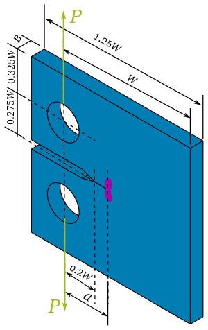
The stress intensity factor at the crack tip of a compact tension specimen is[4]
![{\displaystyle K_{\rm {I}}={\frac {P}{B}}{\sqrt {\frac {\pi }{W}}}\left[16.7\left({\frac {a}{W}}\right)^{1/2}-104.7\left({\frac {a}{W}}\right)^{3/2}+369.9\left({\frac {a}{W}}\right)^{5/2}-573.8\left({\frac {a}{W}}\right)^{7/2}+360.5\left({\frac {a}{W}}\right)^{9/2}\right]}](https://wikimedia.org/api/rest_v1/media/math/render/svg/0c2cc10d13eda5eb359996cde7ef9d0c9a17dd0e)
where is the applied load, is the thickness of the specimen, is the crack length, and is the effective width of the specimen being the distance between the centreline of the holes and the backface of the coupon. The above equation has been fitted using numerical computations for various specimen geometries.


Crack length edit
The length of the crack is often measured indirectly during testing by calculating the crack length from the compliance of the coupon. The compliance can be determined from either a crack mouth opening displacement (CMOD) gauge or from strain measurements on the back-face of the coupon.
Crack mouth opening displacement edit
Crack length can be found using a displacement gauge attached to the mouth of the coupon to measure displacements using the equation[1]


![{\displaystyle u_{x}=\left\{\left[{\frac {EvB}{P}}\right]^{\frac {1}{2}}+1\right\}^{-1}}](https://wikimedia.org/api/rest_v1/media/math/render/svg/aca38aa22b8cac4a21e626aebd9ea38047d276b6)
This equation is applicable in the range .

Back-face strain edit
The crack length can be determined using the back-face strain with the following equation[3]


where , and is the Young's modulus of the coupon material. This equation is applicable in the range .


Electric Potential Difference edit
The crack length can also be determined from voltage measurements of the electric potential difference (EPD) at points at each side of the mouth of the machined slot at opposite sides of the coupon using[1]

where is the measured EPD voltage and is the reference crack voltage corresponding to on an identical specimen. This equation is requires the electrical excitation current is injected along the load line of the specimen. This equation is applicable in the range .


References edit
- ^ a b c ASTM E647-00 Standard Test Method for Measurement of Fatigue Crack Growth Rates. ASTM International, 2000.
- ^ ISO 7539-6 Corrosion of metals and alloys - Stress corrosion testing - Part 6: Preparation and use of pre-cracked specimens for tests under constant load or constant displacement. 2nd Ed. 2003.
- ^ a b Newman, J. C.; Yamada, Y.; James, M. A. (2011). "Back-face strain compliance relation for compact specimens for wide range in crack lengths". Engineering Fracture Mechanics. 78 (15): 2707–2711. doi:10.1016/j.engfracmech.2011.07.001.
- ^ Bower, A. F. (2009). Applied mechanics of solids. CRC Press.