


Summary
In microtomography X-ray scanners, cone beam reconstruction is one of two common scanning methods, the other being Fan beam reconstruction.[1]
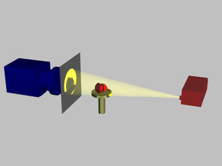
Cone beam reconstruction uses a 2-dimensional approach for obtaining projection data. Instead of utilizing a single row of detectors, as fan beam methods do, a cone beam systems uses a standard charge-coupled device camera, focused on a scintillator material. The scintillator converts X-ray radiation to visible light, which is picked up by the camera and recorded. The method has enjoyed widespread implementation in microtomography, and is also used in several larger-scale systems.
An X-ray source is positioned across from the detector, with the object being scanned in between. (This is essentially the same setup used for an ordinary X-ray fluoroscope).
Projections from different angles are obtained in one of two ways. In one method, the object being scanned is rotated. This has the advantage of simplicity in implementation; a rotating stage results in little complexity. The second method involves rotating the X-ray source and camera around the object, as is done in ordinary CT scanning and SPECT imaging. This adds complexity, size and cost to the system, but removes the need to rotate the object.

The method is referred to as cone-beam reconstruction because the X-rays are emitted from the source as a cone-shaped beam. In other words, it begins as a tight beam at the source, and expands as it moves away.