


Summary
A course deviation indicator (CDI)[1] is an avionics instrument used in aircraft navigation to determine an aircraft's lateral position in relation to a course to or from a radio navigation beacon. If the location of the aircraft is to the left of this course, the needle deflects to the right, and vice versa.
Use edit
The indicator shows the direction to steer to correct for course deviations. Correction is made until the vertical needle centres, meaning the aircraft has intercepted the given course line. The pilot then steers to stay on that line. Only the receiver's current position determines the reading: the aircraft's heading, orientation, and track are not indicated.
The deflection of the needle is proportional to the course deviation, but sensitivity and deflection vary depending on the system being used:
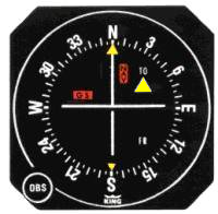
- When used with a VOR or VORTAC, the instrument can be referred to as an "omni bearing indicator" ("OBI").[2] The course line is selected by turning an "omni bearing selector" or "OBS" knob usually located in the lower left of the indicator. It then shows the number of degrees deviation between the aircraft's current position and the "radial" line emanating from the signal source at the given bearing. This can be used to find and follow the desired radial. Deflection is 10° deviation at full scale (each side), with each dot on the CDI representing 2°. (See Using a VOR for usage during flight.)
- When used with a GPS, or other RNAV equipment, it shows actual distance left or right of the programmed course line. Sensitivity is usually programmable or automatically switched, but 5 nautical miles (9.3 km) deviation at full scale is typical for en route operations. Approach and terminal operations have a higher sensitivity up to frequently 0.3 nautical miles (0.56 km) at full scale. In this mode, the OBS knob may or may not have an effect, depending on configuration.[3]
- When used for instrument approaches using a LDA or ILS the OBS knob has no function because the course line is usually the runway heading, and is determined by the ground transmitter. A CDI might incorporate a horizontal needle to provide vertical guidance when used with a precision ILS approach where the glideslope is broadcast by another transmitter located on the ground.
A CDI is not used with an automatic direction finder (ADF), which receives information from a normal AM radio station or an NDB.
Operation edit
The CDI was designed to interpret a signal from a VOR, LDA, or ILS receiver. These receivers output a signal composed of two AC voltages. When used with a VOR, a converter decodes this signal, and, by determining the desired heading or radial from a resolver connected to the OBS knob, provides a 150mV control signal to drive the CDI needle left or right. Most older units and some newer ones integrate a converter with the CDI. CDI units with an internal converter are not compatible with GPS units. More modern units are driven by a converter that is standalone or integrated with the radio. The resolver position is sent to the converter which outputs the control signal to drive the CDI. For digital units, the desired position of the needle is transmitted via a serial ARINC 429 signal from the radio or GPS unit, allowing the CDI design to be independent of the receiver and by multiple receiver types.
See also edit
References edit
- ^ FAA (2016). "16. Navigation". Pilot's Handbook of Aeronautical Knowledge (PDF). p. 23.
The CDI is found in most training aircraft. It consists of an omnibearing selector (OBS) sometimes referred to as the course selector, a CDI needle (left-right needle), and a TO/ FROM indicator.
- ^ Radio Navigation & Instrument Flying. Air Pilot Publishing Ltd. 2008. ISBN 978-1-84336-069-8.
- ^ "400 Series Installation Manual" (PDF). p. 5.10. Archived from the original (PDF) on 2016-11-24. Retrieved 2016-11-23.
External links edit
- Flash VOR type Course Deviation Indicator Simulator