


Summary
A double tee or double-T beam is a load-bearing structure that resembles two T-beams connected to each other side by side. The strong bond of the flange (horizontal section) and the two webs (vertical members, also known as stems) creates a structure that is capable of withstanding high loads while having a long span. The typical sizes of double tees are up to 15 feet (4.6 m) for flange width, up to 5 feet (1.5 m) for web depth, and up to 80 feet (24 m) or more for span length. Double tees are pre-manufactured from prestressed concrete which allows construction time to be shortened.[1]

History edit
The developments of double tee were started in the 1950s by two independent initiatives, one by Leap Associates founded by Harry Edwards in Florida, and the other by Prestressed Concrete of Colorado. They designed the wings to expand the structural channel in order to cover more area at a lower cost.[2] In 1951, Harry Edwards and Paul Zia designed a 4-foot (1.2 m) wide prestressed double tee section. Non-prestressed double tees were constructed in Miami in 1952 followed by prestressed double tees in 1953. Separately, engineers of Prestressed Concrete of Colorado developed and constructed the first prestressed double tee which was 6-foot (1.8 m) wide called "twin tee" in late 1952. The early twin tee spans were between 20 feet (6.1 m) and 25 feet (7.6 m). Those double tee spans were first used for the first time to build a cold storage building for Beatrice Foods in Denver.[3]
The early double tee spans of 25 feet (7.6 m) had grown to 50 feet (15 m) quickly. The Precast/Prestressed Concrete Institute (PCI) published the double tee load capacity calculation (load tables) for the first time in the PCI Design Handbook in 1971. The load tables use the code to identify double tee span type by using the width in feet, followed by "DT", followed by depth in inches, for example, 4DT14 is for 4-foot (1.2 m) wide, 14-inch (36 cm) deep double tees. In its first publication there were seven double tee types from 4DT14 to 10DT32. The list included 8DT24 that were proven to be the most popular double tee type used for 60-foot (18 m) spans for several decades. Currently, the common double tee type is 12DT30 with 4 inches (10 cm) pretopped surface on the flange. This type has been included in the PCI Design Handbook since 1999.[3]
The first building with all pre-stressed concrete columns, beams, and double tees was a two-story office building in Winter Haven, Florida, designed and built in 1961 by Gene Leedy. Leedy experimented when building his architectural office by using structural elements of prestressed concrete and designing the new "double-tee" structural elements.[4]
In their early days, the applications of double tees were limited to multi-story car park structures and roof structures of buildings, but they have now been used in highway structures as well.[1]
Manufacturing process edit
Double tees are manufactured in factories. The process is the same as in other prestressed concrete manufacturing by building them on pretensioning beds. The beds for making double tees are of the typical sizes of the area that double tees will be used. In most cases, the lengths of the pretensioning beds are of about 200 to 500 feet (61 to 152 m) long.[1]
Applications edit
Roofing edit
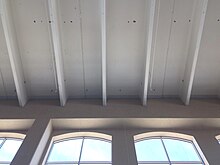
In non-residential buildings, the roof structure may be flat. Structural concrete is an alternative for flat roof construction. There are three main categories for such method: precast/prestressed, cast-in-place and shell. Within the precast/prestressed concrete roofing, the double tees are the most common products used for roof span up to 60 feet (18 m).[5]
Parking structures edit

Modern multi-story parking structures are built from precast/prestressed concrete systems. The floor systems are mostly built from pre-topped double tees. This system evolved from the earlier use of tee systems where the flanges of the T-beams were connected. The concrete is then poured at the top of the tees during the construction to create the floor surface, hence the process is called field-placed concrete topping. In double-tee structures, the top concrete is usually made at the factory as an integral part of the precast double tee structure. Double tees are connected during the construction without topping with concrete to create the parking structure floor surface.[6]
A benefit of pre-topped double tees is a higher quality concrete for more durable surface to reduce traffic wears. Factories can produce the topping with minimum concrete strength of 5,000 psi. In some areas, the strength can be 6,000-8,000 psi. This compares to the field-placed concrete topping with the lower concrete strength of 4,000 psi.[6]
Typically, the double-tees are hung over a supporting structure. This is done by having dapped ends at the webs of the double tee (pictured). The dapped ends are sensitive to cracking at the supporting area. A recommendation to prevent cracking is to include reinforcing steel in the double-tee design to transfer the loads from the bearing area (the reduced-depth section) to the full-depth section of the web.[6] In case that the cracks are developed after the parking structure is already in use, other methods to provide external support to the double-tees are needed. One of such alternatives is to use externally bonded carbon fiber reinforced polymer (FRP) to provide reinforcement.[7]
Bridges edit

Prefabricated bridge designs have been used in many bridge constructions to reduce the construction time. In the United States, there are efforts to come up with Prefabricated Bridge Elements and Systems in many states. Double tee structure is an alternative for short to medium spans between 40 and 90 feet (12 and 27 m). There are many standards such as double-tee beam of Texas Department of Transportation and the Northeast Extreme Tee (NEXT) Beam of the Northeast.[8]
A benefit of using double tees for bridge replacements is to shorten the construction time. Texas has a goal of shortening short-span bridge replacements to one month or less instead of 6 months in traditional bridge constructions.[9]
NEXT Beam development started in 2006 by the Precast/Prestressed Concrete Institute (PCI) North East to update regional standard on Accelerated Bridge Construction (ABC). The NEXT Beam design was inspired by double-tee designs that have been used to build railroad platform slabs. The use of double tees with wide flange permits fewer beams and to have them stay in place to form the deck, resulting in a shorter construction time. The first design was introduced in 2008 called "NEXT F" with 4-inch (10 cm) flange thickness requires 4-inch (10 cm) topping. This was used for the construction of the Maine State Route 103 bridge that crosses the York River. The seven-span 510-foot (160 m) long bridge was completed in 2010 as the first NEXT Beam bridge. The second design was introduced in 2010 for Sibley Pond Bridge at the border of Canaan and Pittsfield, Maine. The design was called "NEXT D" with 8-inch (20 cm) flange thickness that does not require deck topping, allowing the wearing surface to be applied directly on to the beams. The combination of F and D called "NEXT E" was introduced in 2016.[10][11]
Concerns of using double tees in bridge constructions include bridge deck longitudinal cracks. As the connection points between the double tee beams are longitudinally along the traffic flow, any lateral movements of double tees can cause the road surface to crack longitudinally. These include differential rotation of double-tee flanges that can cause asphalt surface to raise or crack. A separation of the flanges can cause asphalt to sag into the gap forming a reflective crack. To reduce these problems, many methods have been developed to manage the lateral connections of the double tees. The materials used in the connections are backer rods, steel bars, welded plates, and grouts.[12]
Walls edit
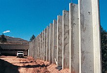

Double tees have been used in vertical load-bearing members such as exterior walls,[3] and retaining walls.[13]
When using load-bearing double tee wall panels, it can significantly reduce construction time as a large area of walls can be covered in a short amount of time. Using load-bearing double tee wall panels in conjunction with double tee roof can reduce the amount of interior columns because double tee roof members can have long spans and the ends are connected to double tee walls to transfer the loads. Additionally, the ceiling can be raised higher as double tee wall members can have long spans also. This is suitable for warehouses as a large area with high ceiling is needed but without windows. This type of construction has been used since the 1970s.[14] Precast Prestressed Concrete Institute included double tee wall panels in its PCI Design Handbook between 1971 and 2010.[15]
References edit
- ^ a b c Gurley, Evan; Hanson, Kayla (13 October 2014). "Strength to a Double Tee". Precast Solutions Magazine. Retrieved 26 April 2015.
- ^ Scott, Norma L. "Reflections on the Early Precast/Prestressed Concrete Industry in America" (PDF). PCI Journal (March–April 2004): 24. Retrieved 23 October 2020.
- ^ a b c Nasser, George D.; Tadros, Maher; Sevenker, Adam; Nasser, David. "The legacy and future of an American icon: The precast, prestressed concrete double tee" (PDF). PCI Journal (July–August 2015). Retrieved 23 October 2020.
- ^ "Building a Day: October 14, 2014". Center for Architecture Sarasota. 14 October 2014. Archived from the original on 26 May 2015. Retrieved 26 April 2015.
- ^ "Concrete Roof Systems Part 1: Precast/Prestressed Constructions" (PDF). Archived from the original (PDF) on 26 May 2015. Retrieved 26 May 2015.
{{cite journal}}: Cite journal requires|journal=(help) - ^ a b c Promotion, PCI Committee on Parking Structures, PCI Committee on Parking Marketing & (1997). Precast prestressed concrete parking structures : recommended practice for design and construction (PDF). Chicago: Precast/Prestressed Concrete Institute. pp. 1–7, 3–4, 3–5, 4–4, 4–20. ISBN 0-937040-58-4. Archived from the original (PDF) on 26 May 2015. Retrieved 27 April 2015.
{{cite book}}: CS1 maint: multiple names: authors list (link) - ^ Gold, William J.; Blaszak, Gregg J.; Mettemeyer, Matt; Nanni, Antonio; Wuerthele, Michael D. (8 May 2000). "Strengthening Dapped Ends of Precast Double Tees with Externally Bonded FRP Reinforcement" (PDF). ASCE Structures Congress 2000: 1–9. doi:10.1061/40492(2000)172. ISBN 9780784404928. Archived from the original (PDF) on 4 March 2016. Retrieved 2 May 2015.
- ^ Prefabricated/Precast Bridge Elements and Systems (PBES) for Off-System Bridges (PDF). FAMU-FSU College of Engineering. August 2012. Archived from the original (PDF) on 18 March 2018. Retrieved 15 July 2020.
- ^ "Case Study 3: Short-span Local Bridges in Texas". US Department of Transportation. Retrieved 2 May 2015.
- ^ ABC – UTC Webinar 2-15-18 Northeast Extreme Tee (NEXT) Beam with Rochester VT Case Study (PDF). Precast/Prestressed Concrete Institute Northeast. 15 February 2018. Retrieved 15 July 2020.
- ^ Gardner, Lauren S.; Hodgdon, Steven M. "The first NEXT beam bridge" (PDF). PCI Journal. Winter 2013: 55–62. Retrieved 15 July 2020.
- ^ Jones, Harry L. (April 2001). "Lateral Connections for Double Tee Bridges" (PDF). Fhwa/Tx-01/1856-2. Retrieved 2 May 2015.
- ^ Moler, Steve (March–April 2004). "A Tale of Two Canyons". Public Roads. 67 (5). Retrieved 27 October 2022.
- ^ "Precast Prestressed Building System Cuts Erection Time of Warehouse/Office" (PDF). PCI Journal: 120–123. Jan–Feb 1974. Retrieved 19 May 2023.
- ^ "Design Tables & Charts". Precast Prestressed Concrete Institute. Retrieved 19 May 2023.