


Summary
A fiber-reinforced composite (FRC) is a composite building material that consists of three components:[1][2]
- the fibers as the discontinuous or dispersed phase,
- the matrix as the continuous phase, and
- the fine interphase region, also known as the interface.
This is a type of advanced composite group, which makes use of rice husk, rice hull,rice shell, and plastic as ingredients. This technology involves a method of refining, blending, and compounding natural fibers from cellulosic waste streams to form a high-strength fiber composite material in a polymer matrix. The designated waste or base raw materials used in this instance are those of waste thermoplastics and various categories of cellulosic waste including rice husk and saw dust.
Introduction edit
FRC is high-performance fiber composite achieved and made possible by cross-linking cellulosic fiber molecules with resins in the FRC material matrix through a proprietary molecular re-engineering process, yielding a product of exceptional structural properties.
Through this feat of molecular re-engineering selected physical and structural properties of wood are successfully cloned and vested in the FRC product, in addition to other critical attributes to yield performance properties superior to contemporary wood.
This material, unlike other composites, can be recycled up to 20 times, allowing scrap FRC to be reused again and again.
The failure mechanisms in FRC materials include delamination, intralaminar matrix cracking, longitudinal matrix splitting, fiber/matrix debonding, fiber pull-out, and fiber fracture.[1]
Difference between wood plastic composite and fiber-reinforced composite:
| Features | Plastic lumber | Wood plastic composite | FRC | Wood |
|---|---|---|---|---|
| Recyclable | Yes | No | Yes | Yes |
| House Construction | No | No | Yes | Yes |
| Water Absorption | 0.00% | 0.8% and above | 0.3% and below | 10% and above |
Properties edit
| Tensile Strength | ASTM D 638 | 15.9 MPa |
| Flexural Strength | ASTM D 790 | 280 MPa |
| Flexural Modulus | ASTM D 790 | 1582 MPa |
| Failure Load | ASTM D 1761 | 1.5 KN - 20.8 KN |
| Compressive Strength | 20.7MPa | |
| Heat Reversion | BS EN 743 : 1995 | 0.45% |
| Water Absorption | ASTM D 570 | 0.34% |
| Termite Resistant | FRIM Test Method | 3.6 |
Basic principles edit
The appropriate "average" of the individual phase properties to be used in describing composite tensile behavior can be elucidated with reference to Fig. 6.2. Although
this figure illustrates a plate-like composite, the results that follow are equally applicable to fiber composites having similar phase arrangements. The two phase
material of Fig. 6.2 consists of lamellae of and phases of thickness and . and respectively. Thus, the volume fractions ( , ) of the phases are and .


Case I: Same stress, different strain
A tensile force F is applied normal to the broad faces (dimensions Lx L) of the phases. In this arrangement the stress borne by each of the phases (= F/ ) is the same, but the strains ( , ) they experience are different. composite strain is a volumetric weighted average of the strains of the individual phases.


,


The total elongation of the composite, is obtained as


and the composite strain is, = = =


Composite modulus

Case II: different stress, same strain
Fibers that are aligned parallel to the tensile axis, the strains in both phases are equal (and the same as the composite strain), but the external force is partitioned
unequally between the phases.


Deformation behavior edit
When the fiber is aligned parallel to the direction of the matrix and applied the load as the same strain case. The fiber and matrix has the volume fraction , ; stress , ; strain , ; and modulus , . And here = = . The uniaxial stress-strain response of a fiber composite can be divided into several stages.


In stage 1, when the fiber and matrix both deform elastically, the stress and strain relation is


In stage 2, when the stress for the fiber is bigger than the yield stress, the matrix starts to deform plastically, and the fiber are still elastic, the stress and strain relation is


In stage 3, when the matrix the fiber both deform plastically, the stress and strain relation is


Since some fibers do not deform permanently prior to fracture, stage 3 cannot be observed in some composite.
In stage 4, when the fiber has already become fracture and matrix still deforms plastically, the stress and strain relation is

However, it is not completely true, since the failure fibers can still carry some load.
Reinforcement with discontinuous fibers edit
For discontinuous fibers (also known as whiskers, depending on the length), tensile force is transmitted from the matrix to the fiber by means of shear stresses that develop along the fiber-matrix interface.
Matrix has displacement equals zero at fiber midpoint and maximum at ends relative to the fiber along the interface. Displacement causes interfacial shear stress that is balanced with fiber tensile stress . is the fiber diameter, and is the distance from the fiber end.


After only a very small strain, the magnitude of the shear stress at the fiber end becomes large. This leads to two situation: fiber-matrix delamination or matrix having plastic shear.
If matrix has plastic shear: interfacial shear stress . Then there is a critical length that when , after certain , remains constant and equals to stress in equal-strain condition.


The ratio, is called the "critical aspect ratio". It increases with composite strain . For the mid-point of a fiber to be stressed to the equal-strain condition at composite fracture, its length must be at least .


Then calculate average stress. The fraction of the fiber length carrying stress is . The remaining fraction bears an average stress .


![{\displaystyle {\overline {\sigma }}_{f}=\sigma _{f}(\varepsilon _{c})\left[1-\left({\frac {l_{c}}{l}}\right)\right]+{\frac {1}{2}}\sigma _{f}(\varepsilon _{c})\left({\frac {l_{c}}{l}}\right)=\sigma _{f}(\varepsilon _{c})\left[1-\left({\frac {l_{c}}{2l}}\right)\right]\quad l\geq l_{c}}](https://wikimedia.org/api/rest_v1/media/math/render/svg/aad0fee9af882fb856bd59892fa30c98d9d46439)
For , average stress is with .


The composite stress is modified as following:
![{\displaystyle \sigma _{c}=V_{f}\sigma _{f}(\varepsilon _{c})\left[1-\left({\frac {l_{c}}{2l}}\right)\right]+V_{m}\sigma _{m}(\varepsilon _{m})\quad l\geq l_{c}}](https://wikimedia.org/api/rest_v1/media/math/render/svg/a7e136ed0f7b0ffc50d3a6a9463882bcdbe854b0)

The above equations assumed the fibers were aligned with the direction of loading. A modified rule of mixtures can be used to predict composite strength, including an orientation efficiency factor, , which accounts for the decrease in strength from misaligned fibers.[3]


where is the fiber efficiency factor equal to for , and for . If the fibers are perfectly aligned with the direction of loading is 1. However, common values of for randomly oriented are roughly 0.375 for an in-plane two-dimensional array and 0.2 for a three-dimensional array.[3]


![{\displaystyle \left[1-\left({\frac {l_{c}}{2l}}\right)\right]}](https://wikimedia.org/api/rest_v1/media/math/render/svg/1ce1f8185734f9a545040f59fe812b457e38407a)
Appreciable reinforcement can be provided by discontinuous fibers provided their lengths are much greater than the (usually) small critical lengths. Such as MMCs.
If there is fiber-matrix delamination. is replaced by friction stress where is the friction coefficient between the matrix and the fiber, and is an internal pressure.


This happens in most resin-based composites.
Composites with fibers length less than contribute little to strength. However, during composite fracture, the short fibers do not fracture. Instead they are pulled out of the matrix. The work associated with fiber pull-out provides an added component to the fracture work and has a great contribution to toughness.
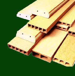
Application edit
There are also applications in the market, which utilize only waste materials. Its most widespread use is in outdoor deck floors, but it is also used for railings, fences, landscaping timbers, cladding and siding, park benches, molding and trim, window and door frames, and indoor furniture. See for example the work of Waste for Life, which collaborates with garbage scavenging cooperatives to create fiber-reinforced building materials and domestic problems from the waste their members collect: Homepage of Waste for Life
Adoption of natural fiber in reinforced polymer composites potentially to be used in automotive industry could significantly help developing a sustainable waste management.[4]
See also edit
References edit
- ^ a b WJ Cantwell, J Morton (1991). "The impact resistance of composite materials -- a review". Composites. 22 (5): 347–62. doi:10.1016/0010-4361(91)90549-V.
- ^ Serope Kalpakjian, Steven R Schmid. "Manufacturing Engineering and Technology". International edition. 4th Ed. Prentice Hall, Inc. 2001. ISBN 0-13-017440-8.
- ^ a b Soboyejo, W. O. (2003). "9.7 Effects of Whisker/Fiber Length on Composite Strength and Modulus". Mechanical properties of engineered materials. Marcel Dekker. ISBN 0-8247-8900-8. OCLC 300921090.
- ^ AL-Oqla, Faris M.; Sapuan, S. M. (2014-03-01). "Natural fiber reinforced polymer composites in industrial applications: feasibility of date palm fibers for sustainable automotive industry" (PDF). Journal of Cleaner Production. 66: 347–354. doi:10.1016/j.jclepro.2013.10.050. ISSN 0959-6526.
3. Thomas H. Courtney. "Mechanical Behavior of Materials". 2nd Ed. Waveland Press, Inc. 2005. ISBN 1-57766-425-6