Passengers in a vehicle accelerating in the forward direction may perceive they are acted upon by a force moving them into the direction of the backrest of their seats for instance. An example in a rotating reference frame may be the impression that it is a force which seems to move objects outward toward the rim of a centrifuge or carousel.
The fictitious force called a pseudo force might also be referred to as a body force. It is due to an object's inertia when the reference frame does not move inertially any more but begins to accelerate relative to the free object. In terms of the example of the passenger vehicle, a pseudo force seems to be active just before the body touches the backrest of the seat in the car. A person in the car leaning forward first moves a bit backward in relation to the already accelerating car, before touching the backrest. The motion in this short period just seems to be the result of a force on the person; i.e., it is a pseudo force. A pseudo force does not arise from any physical interaction between two objects, such as electromagnetism or contact forces. It's just a consequence of the acceleration a of the physical object the non-inertial reference frame is connected to, i.e. the vehicle in this case. From the viewpoint of the respective accelerating frame, an acceleration of the inert object appears to be present, apparently requiring a "force" for this to have happened.
Such an additional force due to nonuniform relative motion of two reference frames is called a pseudo-force.
— Harald Iro in A Modern Approach to Classical Mechanics p. 180
The pseudo force on an object arises as an imaginary influence when the frame of reference used to describe the object's motion is accelerating compared to a non-accelerating frame. The pseudo force "explains," using Newton's second law mechanics, why an object does not follow Newton's second law and "floats freely" as if weightless. As a frame may accelerate in any arbitrary way, so may pseudo forces also be as arbitrary (but only in direct response to the acceleration of the frame). An example of a pseudo force as defined by Iro is the Coriolis force, maybe better to be called: the Coriolis effect.[4][5][6] The gravitational force would also be a fictitious force (pseudo force), based upon a field model in which particles distort spacetime due to their mass, such as in the theory of general relativity.
Assuming Newton's second law in the form F = ma, fictitious forces are always proportional to the mass m.
The fictitious force that has been called an inertial force[7][8][9] is also referred to as a d'Alembert force,[10][11] or sometimes as a pseudo force.[12] D'Alembert's principle is just another way of formulating Newton's second law of motion. It defines an inertial force as the negative of the product of mass times acceleration, just for the sake of easier calculations.
(A d'Alembert force is not to be confused with a contact force arising from the physical interaction between two objects, which is the subject of Newton's third law – 'action is reaction'.[13][14] In terms of the example of the passenger vehicle above, a contact force emerges when the body of the passenger touches the backrest of the seat in the car. It is present for as long as the car is accelerated.)
Four fictitious forces have been defined for frames accelerated in commonly occurring ways:
one caused by any acceleration relative to the origin in a straight line (rectilinear acceleration);[15]
and a fourth, called the Euler force, caused by a variable rate of rotation, should that occur.
Backgroundedit
The role of fictitious forces in Newtonian mechanics is described by Tonnelat:[16]
For Newton, the appearance of acceleration always indicates the existence of absolute motion – absolute motion of matter where real forces are concerned; absolute motion of the reference system, where so-called fictitious forces, such as inertial forces or those of Coriolis, are concerned.
— Marie-Antoinette Tonnelat in The Principles of Electromagnetic Theory and Relativity, p.113
Fictitious forces arise in classical mechanics and special relativity in all non-inertial frames.
Inertial frames are privileged over non-inertial frames because they do not have physics whose causes are outside of the system, while non-inertial frames do. Fictitious forces, or physics whose cause is outside of the system, are no longer necessary in general relativity, since these physics are explained with the geodesics of spacetime: "The field of all possible space-time null geodesics or photon paths unifies the absolute local non-rotation standard throughout space-time.".[17]
On Earthedit
The surface of the Earth is a rotating reference frame. To solve classical mechanics problems exactly in an Earthbound reference frame, three fictitious forces must be introduced: the Coriolis force, the centrifugal force (described below) and the Euler force. The Euler force is typically ignored because the variations in the angular velocity of the rotating surface of the Earth are usually insignificant. Both of the other fictitious forces are weak compared to most typical forces in everyday life, but they can be detected under careful conditions. For example, Léon Foucault used his Foucault pendulum to show that a Coriolis force results from the Earth's rotation.
If the Earth were to rotate twenty times faster (making each day only ~72 minutes long), people could easily get the impression that such fictitious forces were pulling on them, as on a spinning carousel; people in temperate and tropical latitudes would, in fact, need to hold on in order to avoid being launched into orbit by the centrifugal force.
Detection of non-inertial reference frameedit
Observers inside a closed box that is moving with a constant velocity cannot detect their own motion; however, observers within an accelerating reference frame can detect that they are in a non-inertial reference frame from the fictitious forces that arise. For example, for straight-line acceleration Vladimir Arnold presents the following theorem:[18]
In a coordinate system K which moves by translation relative to an inertial system k, the motion of a mechanical system takes place as if the coordinate system were inertial, but on every point of mass m an additional "inertial force" acted: F = −ma, where a is the acceleration of the system K.
Other accelerations also give rise to fictitious forces, as described mathematically below. The physical explanation of motions in an inertial frame is the simplest possible, requiring no fictitious forces: fictitious forces are zero, providing a means to distinguish inertial frames from others.[19]
An example of the detection of a non-inertial, rotating reference frame is the precession of a Foucault pendulum. In the non-inertial frame of the Earth, the fictitious Coriolis force is necessary to explain observations. In an inertial frame outside the Earth, no such fictitious force is necessary.
Example concerning Circular motionedit
In the inertial frame of reference (upper part of the picture), the black ball moves in a straight line. However, the observer (brown dot) who is standing in the rotating/non-inertial frame of reference (lower part of the picture) sees the object as following a curved path due to the Coriolis or centrifugal forces present in this frame.
The effect of a fictitious force also occurs when a car takes the bend. Observed from a non-inertial frame of reference attached to the car, the fictitious force called the centrifugal force appears. As the car enters a left turn, a suitcase first on the left rear seat slides to the right rear seat and then continues until it comes into contact with the closed door on the right. This motion marks the phase of the fictitious centrifugal force as it is the inertia of the suitcase which plays a role in this piece of movement. It may seem that there must be a force responsible for this movement, but actually, this movement arises because of the inertia of the suitcase, which is (still) a 'free object' within an already accelerating frame of reference.
After the suitcase has come into contact with the closed door of the car, the situation with the emergence of contact forces becomes current. The centripetal force on the car is now also transferred to the suitcase and the situation of Newton's third law comes into play, with the centripetal force as the action part and with the so-called reactive centrifugal force as the reaction part. The reactive centrifugal force is also due to the inertia of the suitcase. Now however the inertia appears in the form of a manifesting resistance to a change in its state of motion.
[20]
Suppose a few miles further the car is moving at constant speed travelling a roundabout, again and again, then the occupants will feel as if they are being pushed to the outside of the vehicle by the (reactive) centrifugal force, away from the centre of the turn.
The situation can be viewed from inertial as well as from non-inertial frames.
From the viewpoint of an inertial reference frame stationary with respect to the road, the car is accelerating toward the centre of the circle. It is accelerating, because the direction of the velocity is changing, despite the car having constant speed. This inward acceleration is called centripetal acceleration, it requires a centripetal force to maintain the circular motion. This force is exerted by the ground upon the wheels, in this case, from the friction between the wheels and the road.[21] The car is accelerating, due to the unbalanced force, which causes it to move in a circle. (See also banked turn.)
From the viewpoint of a rotating frame, moving with the car, a fictitious centrifugal force appears to be present pushing the car toward the outside of the road (and pushing the occupants toward the outside of the car). The centrifugal force balances the friction between wheels and the road, making the car stationary in this non-inertial frame.
A classic example of a fictitious force in circular motion is the experiment of rotating spheres tied by a cord and spinning around their centre of mass. In this case, the identification of a rotating, non-inertial frame of reference can be based upon the vanishing of fictitious forces. In an inertial frame, fictitious forces are not necessary to explain the tension in the string joining the spheres. In a rotating frame, Coriolis and centrifugal forces must be introduced to predict the observed tension.
In the rotating reference frame perceived on the surface of the Earth, a centrifugal force reduces the apparent force of gravity by about one part in a thousand, depending on latitude. This reduction is zero at the poles, maximum at the equator.
Animation: object released from a carousel
Map and spin frame perspectives of physical (red) and fictitious (blue) forces for an object released from a carousel
For someone in the map perspective only one force is sufficient to explain the motion: the red arrow: centripetal force. After release, the number of forces is zero. For someone in the spinning frame the object moves in a complicated way that needs a centrifugal force: the blue arrow.Note: With some browsers, hitting [Esc] will freeze the motion for more detailed analysis. However, the page may have to be reloaded to restart.
The fictitious Coriolis force, which is observed in rotational frames, is ordinarily visible only in very large-scale motion like the projectile motion of long-range guns or the circulation of the Earth's atmosphere (see Rossby number). Neglecting air resistance, an object dropped from a 50-meter-high tower at the equator will fall 7.7 millimetres eastward of the spot below where it is dropped because of the Coriolis force.[22]
Fictitious forces and workedit
Fictitious forces can be considered to do work, provided that they move an object on a trajectory that changes its energy from potential to kinetic. For example, consider some persons in rotating chairs holding a weight in their outstretched hands. If they pull their hand inward toward their body, from the perspective of the rotating reference frame, they have done work against the centrifugal force. When the weight is let go, it spontaneously flies outward relative to the rotating reference frame, because the centrifugal force does work on the object, converting its potential energy into kinetic. From an inertial viewpoint, of course, the object flies away from them because it is suddenly allowed to move in a straight line. This illustrates that the work done, like the total potential and kinetic energy of an object, can be different in a non-inertial frame than in an inertial one.
Gravity as a fictitious forceedit
The notion of "fictitious force" also arises in Einstein's general theory of relativity.[23][24] All fictitious forces are proportional to the mass of the object upon which they act, which is also true for gravity.[25][26] This led Albert Einstein to wonder whether gravity could be modeled as a fictitious force. He noted that a freefalling observer in a closed box would not be able to detect the force of gravity; hence, freefalling reference frames are equivalent to inertial reference frames (the equivalence principle). Developing this insight, Einstein formulated a theory with gravity as a fictitious force, and attributed the apparent acceleration due to gravity to the curvature of spacetime. This idea underlies Einstein's theory of general relativity. See the Eötvös experiment.
Animation: ball that rolls off a cliff
Rain and shell frame perspectives of physical (red) and fictitious (blue) forces for an object that rolls off a cliff.Note: The rain frame perspective here, rather than being that of a raindrop, is more like that of a trampoline jumper whose trajectory tops out just as the ball reaches the edge of the cliff. The shell frame perspective[27] may be familiar to planet dwellers who rely minute by minute on upward physical forces from their environment, to protect them from the geometric acceleration due to curved spacetime.
Mathematical derivation of fictitious forces edit
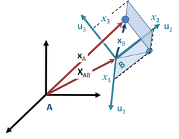
Figure 2: An object located at xA in inertial frame A is located at location xB in accelerating frame B. The origin of frame B is located at XAB in frame A. The orientation of frame B is determined by the unit vectors along its coordinate directions, uj with j = 1, 2, 3. Using these axes, the coordinates of the object according to frame B are xB = ( x1, x2, x3).
General derivationedit
Many problems require use of noninertial reference frames, for example, those involving satellites[28][29] and particle accelerators.[30] Figure 2 shows a particle with massm and positionvectorxA(t) in a particular inertial frame A. Consider a non-inertial frame B whose origin relative to the inertial one is given by XAB(t). Let the position of the particle in frame B be xB(t). What is the force on the particle as expressed in the coordinate system of frame B?[31][32]
To answer this question, let the coordinate axis in B be represented by unit vectors uj with j any of { 1, 2, 3 } for the three coordinate axes. Then
The interpretation of this equation is that xB is the vector displacement of the particle as expressed in terms of the coordinates in frame B at the time t. From frame A the particle is located at:
As an aside, the unit vectors { uj } cannot change magnitude, so derivatives of these vectors express only rotation of the coordinate system B. On the other hand, vector XAB simply locates the origin of frame B relative to frame A, and so cannot include rotation of frame B.
Taking a time derivative, the velocity of the particle is:
The second term summation is the velocity of the particle, say vB as measured in frame B. That is:
The interpretation of this equation is that the velocity of the particle seen by observers in frame A consists of what observers in frame B call the velocity, namely vB, plus two extra terms related to the rate of change of the frame-B coordinate axes. One of these is simply the velocity of the moving origin vAB. The other is a contribution to velocity due to the fact that different locations in the non-inertial frame have different apparent velocities due to the rotation of the frame; a point seen from a rotating frame has a rotational component of velocity that is greater the further the point is from the origin.
To find the acceleration, another time differentiation provides:
Using the same formula already used for the time derivative of xB, the velocity derivative on the right is:
Consequently,
(1)
The interpretation of this equation is as follows: the acceleration of the particle in frame A consists of what observers in frame B call the particle acceleration aB, but in addition, there are three acceleration terms related to the movement of the frame-B coordinate axes: one term related to the acceleration of the origin of frame B, namely aAB, and two terms related to the rotation of frame B. Consequently, observers in B will see the particle motion as possessing "extra" acceleration, which they will attribute to "forces" acting on the particle, but which observers in A say are "fictitious" forces arising simply because observers in B do not recognize the non-inertial nature of frame B.
The factor of two in the Coriolis force arises from two equal contributions: (i) the apparent change of an inertially constant velocity with time because rotation makes the direction of the velocity seem to change (a dvB/dt term) and (ii) an apparent change in the velocity of an object when its position changes, putting it nearer to or further from the axis of rotation (the change in due to change in x j ).
To put matters in terms of forces, the accelerations are multiplied by the particle mass:
The force observed in frame B, FB = maB is related to the actual force on the particle, FA, by
where:
Thus, problems may be solved in frame B by assuming that Newton's second law holds (with respect to quantities in that frame) and treating Ffictitious as an additional force.[18][33][34]
Below are a number of examples applying this result for fictitious forces. More examples can be found in the article on centrifugal force.
Rotating coordinate systemsedit
A common situation in which noninertial reference frames are useful is when the reference frame is rotating. Because such rotational motion is non-inertial, due to the acceleration present in any rotational motion, a fictitious force can always be invoked by using a rotational frame of reference. Despite this complication, the use of fictitious forces often simplifies the calculations involved.
To derive expressions for the fictitious forces, derivatives are needed for the apparent time rate of change of vectors that take into account time-variation of the coordinate axes. If the rotation of frame 'B' is represented by a vector Ω pointed along the axis of rotation with the orientation given by the right-hand rule, and with magnitude given by
then the time derivative of any of the three unit vectors describing frame B is[33][35]
and
as is verified using the properties of the vector cross product. These derivative formulas now are applied to the relationship between acceleration in an inertial frame, and that in a coordinate frame rotating with time-varying angular velocity ω(t). From the previous section, where subscript A refers to the inertial frame and B to the rotating frame, setting aAB = 0 to remove any translational acceleration, and focusing on only rotational properties (see Eq. 1):
Collecting terms, the result is the so-called acceleration transformation formula:[36]
The physical accelerationaA due to what observers in the inertial frame A call real external forces on the object is, therefore, not simply the acceleration aB seen by observers in the rotational frame B, but has several additional geometric acceleration terms associated with the rotation of B. As seen in the rotational frame, the acceleration aB of the particle is given by rearrangement of the above equation as:
The net force upon the object according to observers in the rotating frame is FB = maB. If their observations are to result in the correct force on the object when using Newton's laws, they must consider that the additional force Ffict is present, so the end result is FB = FA + Ffict. Thus, the fictitious force used by observers in B to get the correct behaviour of the object from Newton's laws equals:
Figure 3: An orbiting but fixed orientation coordinate system B, shown at three different times. The unit vectors uj, j = 1, 2, 3 do not rotate, but maintain a fixed orientation, while the origin of the coordinate system B moves at constant angular rate ω about the fixed axis Ω. Axis Ω passes through the origin of inertial frame A, so the origin of frame B is a fixed distance R from the origin of inertial frame A.
As a related example, suppose the moving coordinate system B rotates with a constant angular speed ω in a circle of radius R about the fixed origin of inertial frame A, but maintains its coordinate axes fixed in orientation, as in Figure 3. The acceleration of an observed body is now (see Eq. 1):
where the summations are zero inasmuch as the unit vectors have no time dependence. The origin of the system B is located according to frame A at:
leading to a velocity of the origin of frame B as:
leading to an acceleration of the origin of B given by:
Because the first term, which is
is of the same form as the normal centrifugal force expression:
it is a natural extension of standard terminology (although there is no standard terminology for this case) to call this term a "centrifugal force". Whatever terminology is adopted, the observers in frame B must introduce a fictitious force, this time due to the acceleration from the orbital motion of their entire coordinate frame, that is radially outward away from the centre of rotation of the origin of their coordinate system:
and of magnitude:
This "centrifugal force" has differences from the case of a rotating frame. In the rotating frame the centrifugal force is related to the distance of the object from the origin of frame B, while in the case of an orbiting frame, the centrifugal force is independent of the distance of the object from the origin of frame B, but instead depends upon the distance of the origin of frame B from its centre of rotation, resulting in the same centrifugal fictitious force for all objects observed in frame B.
Orbiting and rotatingedit
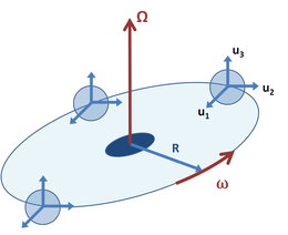
Figure 4: An orbiting coordinate system B similar to Figure 3, but in which unit vectors uj, j = 1, 2, 3 rotate to face the rotational axis, while the origin of the coordinate system B moves at constant angular rate ω about the fixed axis Ω.
As a combination example, Figure 4 shows a coordinate system B that orbits inertial frame A as in Figure 3, but the coordinate axes in frame B turn so unit vector u1 always points toward the centre of rotation. This example might apply to a test tube in a centrifuge, where vector u1 points along the axis of the tube toward its opening at its top. It also resembles the Earth–Moon system, where the Moon always presents the same face to the Earth.[41] In this example, unit vector u3 retains a fixed orientation, while vectors u1, u2 rotate at the same rate as the origin of coordinates. That is,
Hence, the acceleration of a moving object is expressed as (see Eq. 1):
where the angular acceleration term is zero for the constant rate of rotation.
Because the first term, which is
is of the same form as the normal centrifugal force expression:
it is a natural extension of standard terminology (although there is no standard terminology for this case) to call this term the "centrifugal force". Applying this terminology to the example of a tube in a centrifuge, if the tube is far enough from the center of rotation, |XAB| = R ≫ |xB|, all the matter in the test tube sees the same acceleration (the same centrifugal force). Thus, in this case, the fictitious force is primarily a uniform centrifugal force along the axis of the tube, away from the centre of rotation, with a value |Ffict| = ω2R, where R is the distance of the matter in the tube from the centre of the centrifuge. It is the standard specification of a centrifuge to use the "effective" radius of the centrifuge to estimate its ability to provide centrifugal force. Thus, the first estimate of centrifugal force in a centrifuge can be based upon the distance of the tubes from the centre of rotation, and corrections applied if needed.[42][43]
Also, the test tube confines motion to the direction down the length of the tube, so vB is opposite to u1 and the Coriolis force is opposite to u2, that is, against the wall of the tube. If the tube is spun for a long enough time, the velocity vB drops to zero as the matter comes to an equilibrium distribution. For more details, see the articles on sedimentation and the Lamm equation.
A related problem is that of centrifugal forces for the Earth–Moon–Sun system, where three rotations appear: the daily rotation of the Earth about its axis, the lunar-month rotation of the Earth–Moon system about its centre of mass, and the annual revolution of the Earth–Moon system about the Sun. These three motions influence the tides.[44]
Crossing a carouseledit
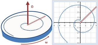
Figure 5: Crossing a rotating carousel walking at a constant speed from the centre of the carousel to its edge, a spiral is traced out in the inertial frame, while a simple straight radial path is seen in the frame of the carousel.
Figure 5 shows another example comparing the observations of an inertial observer with those of an observer on a rotating carousel.[45] The carousel rotates at a constant angular velocity represented by the vector Ω with magnitude ω, pointing upward according to the right-hand rule. A rider on the carousel walks radially across it at a constant speed, in what appears to the walker to be the straight line path inclined at 45° in Figure 5. To the stationary observer, however, the walker travels a spiral path. The points identified on both paths in Figure 5 correspond to the same times spaced at equal time intervals. We ask how two observers, one on the carousel and one in an inertial frame, formulate what they see using Newton's laws.
Inertial observeredit
The observer at rest describes the path followed by the walker as a spiral. Adopting the coordinate system shown in Figure 5, the trajectory is described by r(t):
where the added π/4 sets the path angle at 45° to start with (just an arbitrary choice of direction), uR is a unit vector in the radial direction pointing from the centre of the carousel to the walker at the time t. The radial distance R(t) increases steadily with time according to:
with s the speed of walking. According to simple kinematics, the velocity is then the first derivative of the trajectory:
with uθ a unit vector perpendicular to uR at time t (as can be verified by noticing that the vector dot product with the radial vector is zero) and pointing in the direction of travel.
The acceleration is the first derivative of the velocity:
The last term in the acceleration is radially inward of magnitude ω2R, which is therefore the instantaneous centripetal acceleration of circular motion.[46] The first term is perpendicular to the radial direction, and pointing in the direction of travel. Its magnitude is 2sω, and it represents the acceleration of the walker as the edge of the carousel is neared, and the arc of the circle travelled in a fixed time increases, as can be seen by the increased spacing between points for equal time steps on the spiral in Figure 5 as the outer edge of the carousel is approached.
Applying Newton's laws, multiplying the acceleration by the mass of the walker, the inertial observer concludes that the walker is subject to two forces: the inward radially directed centripetal force and another force perpendicular to the radial direction that is proportional to the speed of the walker.
Rotating observeredit
The rotating observer sees the walker travel a straight line from the centre of the carousel to the periphery, as shown in Figure 5. Moreover, the rotating observer sees that the walker moves at a constant speed in the same direction, so applying Newton's law of inertia, there is zero force upon the walker. These conclusions do not agree with the inertial observer. To obtain agreement, the rotating observer has to introduce fictitious forces that appear to exist in the rotating world, even though there is no apparent reason for them, no apparent gravitational mass, electric charge or what have you, that could account for these fictitious forces.
To agree with the inertial observer, the forces applied to the walker must be exactly those found above. They can be related to the general formulas already derived, namely:
In this example, the velocity seen in the rotating frame is:
with uR a unit vector in the radial direction. The position of the walker as seen on the carousel is:
and the time derivative of Ω is zero for uniform angular rotation. Noticing that
and
we find:
To obtain a straight-line motion in the rotating world, a force exactly opposite in sign to the fictitious force must be applied to reduce the net force on the walker to zero, so Newton's law of inertia will predict a straight line motion, in agreement with what the rotating observer sees. The fictitious forces that must be combated are the Coriolis force (first term) and the centrifugal force (second term). (These terms are approximate.[47]) By applying forces to counter these two fictitious forces, the rotating observer ends up applying exactly the same forces upon the walker that the inertial observer predicted were needed.
Because they differ only by the constant walking velocity, the walker and the rotational observer see the same accelerations. From the walker's perspective, the fictitious force is experienced as real, and combating this force is necessary to stay on a straight line radial path holding a constant speed. It's like battling a crosswind while being thrown to the edge of the carousel.
[48]
Observationedit
Notice that this kinematical discussion does not delve into the mechanism by which the required forces are generated. That is the subject of kinetics. In the case of the carousel, the kinetic discussion would involve perhaps a study of the walker's shoes and the friction they need to generate against the floor of the carousel, or perhaps the dynamics of skateboarding if the walker switched to travel by skateboard. Whatever the means of travel across the carousel, the forces calculated above must be realized. A very rough analogy is heating your house: you must have a certain temperature to be comfortable, but whether you heat by burning gas or by burning coal is another problem. Kinematics sets the thermostat, kinetics fires the furnace.
^Max Born; Günther Leibfried (1962). Einstein's Theory of Relativity. New York: Courier Dover Publications. pp. 76–78. ISBN 0-486-60769-0. inertial forces.
^NASA notes:(23) Accelerated Frames of Reference: Inertial Forces
^Cornelius Lanczos (1986). The Variational Principles of Mechanics. New York: Courier Dover Publications. p. 100. ISBN 0-486-65067-7.
^The Feynman Lectures on Physics Vol. I Ch. 12-5: Pseudo forces
^Physics Forum, "Inertia and Newton's third law". 3 March 2021.
^Physics stack exchange, "about Newton's third law".
^The term d'Alembert force often is limited to this case. See Lanczos, for example.
^Marie-Antoinette Tonnelat (2002). The Principles of Electromagnetic Theory and Relativity. Springer. p. 113. ISBN 90-277-0107-5.
^Gilson, James G. (September 1, 2004), Mach's Principle II, p.1, p.9, arXiv:physics/0409010, Bibcode:2004physics...9010G
^ abVladimir Igorevich Arnold (1989). Mathematical Methods of Classical Mechanics. Berlin: Springer. pp. §27 pp. 129 ff. ISBN 0-387-96890-3.
^As part of the requirement of simplicity, to be an inertial frame, in all other frames that differ only by a uniform rate of translation, the description should be of the same form. However, in the Newtonian system the Galilean transformation connects these frames and in the special theory of relativity the Lorentz transformation connects them. The two transformations agree for speeds of translation much less than the speed of light.
^Science of everyday things, "centripetal force, pp 48-49".
^The force in this example is known as ground reaction, and it could exist even without friction, for example, a sledge running down a curve of a bobsled track.
^Daniel Kleppner; Robert J. Kolenkow (1973). An Introduction to Mechanics. McGraw-Hill. p. 363. ISBN 0-07-035048-5.
^Fritz Rohrlich (2007). Fictitional Forces and apparent gravitational fields. Singapore: World Scientific. p. 40. ISBN 978-981-270-004-9.
^Hans Stephani (2004). Introduction to Special and General Relativity - geodesic deviation p. 104-105. Cambridge UK: Cambridge University Press. p. 105. ISBN 0-521-01069-1.
^
The gravitational mass and the inertial mass are found experimentally to be equal to each other within experimental error.
^Motz and Weaver, Motz, Lloyd; Weaver, Jefferson Hane (11 November 2013). Example train and gravity, p 101. Springer. ISBN 9781489963338.
^Edwin F. Taylor and John Archibald Wheeler (2000) Exploring black holes (Addison Wesley Longman, NY) ISBN 0-201-38423-X
^Alberto Isidori; Lorenzo Marconi; Andrea Serrani (2003). Robust Autonomous Guidance: An Internal Model Approach. Springer. p. 61. ISBN 1-85233-695-1.
^Shuh-Jing Ying (1997). Advanced Dynamics. Reston VA: American Institute of Aeronautics, and Astronautics. p. 172. ISBN 1-56347-224-4. orbit coordinate system.
^Philip J. Bryant; Kjell Johnsen (1993). The Principles of Circular Accelerators and Storage Rings. Cambridge UK: Cambridge University Press. p. xvii. ISBN 0-521-35578-8.[permanent dead link]
^Alexander L Fetter; John D Walecka (2003). Theoretical Mechanics of Particles and Continua. Courier Dover Publications. pp. 33–39. ISBN 0-486-43261-0.
^Yung-kuo Lim; Yuan-qi Qiang (2001). Problems and Solutions on Mechanics: Major American Universities Ph.D. Qualifying Questions and Solutions. Singapore: World Scientific. p. 183. ISBN 981-02-1298-4.
^ abJohn Robert Taylor (2004). Classical Mechanics. Sausalito CA: University Science Books. pp. 343–344. ISBN 1-891389-22-X.
^See for example, JL Synge; BA Griffith (1949). Principles of Mechanics (2nd ed.). McGraw-Hill. pp. 348–349.
^R. Douglas Gregory (2006). Classical Mechanics: An Undergraduate Text. Cambridge UK: Cambridge University Press. pp. Eq. (17.16), p. 475. ISBN 0-521-82678-0.
^Georg Joos; Ira M. Freeman (1986). Theoretical Physics. New York: Courier Dover Publications. p. 233. ISBN 0-486-65227-0.
^Percey F. Smith & William Raymond Longley (1910). Theoretical Mechanics. Boston: Gin. p. 118. centrifugal force theoretical.
^Cornelius Lanczos (1986). The Variational Principles of Mechanics. New York: Courier Dover Publications. p. 103. ISBN 0-486-65067-7.
^Jerold E. Marsden; Tudor.S. Ratiu (1999). Introduction to Mechanics and Symmetry: A Basic Exposition of Classical Mechanical Systems: Texts in applied mathematics, 17 (2nd ed.). NY: Springer-Verlag. p. 251. ISBN 0-387-98643-X.
^However, the Earth–Moon system rotates about its barycenter, not the Earth's center; see Simon Newcomb (2007). Popular Astronomy. Read Books. p. 307. ISBN 978-1-4067-4574-0.
^Bea K Lalmahomed; Sarah Springman; Bhawani Singh (2002). Constitutive and Centrifuge Modelling: Two Extremes. Taylor and Francis. p. 82. ISBN 90-5809-361-1.
^Raymond Nen (1986). Consolidation of Soils: Testing and Evaluation: a Symposium. ASTM International. p. 590. ISBN 0-8031-0446-4.
^D Appleton (1877). The Popular Science Monthly. p. 276.
^For a similar example, see Ron Schmitt (2002). A Handbook for Wireless/ RF, EMC, and High-Speed Electronics, Part of the EDN Series for Design Engineers. Newnes. pp. 60–61. ISBN 0-7506-7403-2., and Douglas C. Giancoli (2007). Physics for Scientists And Engineers With Modern Physics. Pearson Prentice-Hall. p. 301. ISBN 978-0-13-149508-1.
^Note: There is a subtlety here: the distance R is the instantaneous distance from the rotational axis of the carousel. However, it is not the radius of curvatureof the walker's trajectory as seen by the inertial observer, and the unit vector uR is not perpendicular to the path. Thus, the designation "centripetal acceleration" is an approximate use of this term. See, for example, Howard D. Curtis (2005). Orbital Mechanics for Engineering Students. Butterworth-Heinemann. p. 5. ISBN 0-7506-6169-0. and S. Y. Lee (2004). Accelerator physics (2nd ed.). Hackensack NJ: World Scientific. p. 37. ISBN 981-256-182-X.
^A circle about the axis of rotation is not the osculating circle of the walker's trajectory, so "centrifugal" and "Coriolis" are approximate uses for these terms. See note.
^In this connection, it may be noted that a change in the coordinate system, for example, from Cartesian to polar, if implemented without any change in relative motion, does not cause the appearance of rotational fictitious forces, despite the fact that the form of the laws of motion varies from one type of curvilinear coordinate system to another, depending from the (purely spatial) delta-curvature: , where are the contravariant components of the force per unit mass, and are the Christoffel symbols of the second kind, see, for instance: David, Kay, Tensor Calculus (1988) McGraw-Hill Book Company ISBN 0-07-033484-6, Section 11.4; or: Adler, R., Bazin, M., & Schiffer, M. Introduction to General Relativity (New York, 1965). This could be the first hint of the crisis of the non-relativistic physics: in "non-inertial" frames using non-Euclidean and not flat metrics, fictitious forces transform into force exchanged with "objects" that do not follow the geodesic trajectory (simply with a relative speed respect it). In any case this generalized "Newton's second law" must wait for the general relativity to obtain curvature in spacetime according to stress–energy tensor by Einstein field equations and a spacetime form that uses the four-force density tensor that is derived from the covariant divergence of the energy-momentum tensor.
Keith Symon (1971). Mechanics (3rd ed.). Addison-Wesley. ISBN 0-201-07392-7.
Jerry B. Marion (1970). Classical Dynamics of Particles and Systems. Academic Press. ISBN 0-12-472252-0.
Marcel J. Sidi (1997). Spacecraft Dynamics and Control: A Practical Engineering Approach. Cambridge University Press. Chapter 4.8. ISBN 0-521-78780-7.
External linksedit
Q and A from Richard C. Brill, Honolulu Community College
NASA's David Stern: Lesson Plans for Teachers #23 on Inertial Forces
Coriolis Force
Motion over a flat surface Java physlet by Brian Fiedler illustrating fictitious forces. The physlet shows both the perspective as seen from a rotating and from a non-rotating point of view.
Motion over a parabolic surface Java physlet by Brian Fiedler illustrating fictitious forces. The physlet shows both the perspective as seen from a rotating and as seen from a non-rotating point of view.


![{\displaystyle {\frac {d^{2}\mathbf {u} _{j}(t)}{dt^{2}}}={\frac {d{\boldsymbol {\Omega }}}{dt}}\times \mathbf {u} _{j}+{\boldsymbol {\Omega }}\times {\frac {d\mathbf {u} _{j}(t)}{dt}}={\frac {d{\boldsymbol {\Omega }}}{dt}}\times \mathbf {u} _{j}+{\boldsymbol {\Omega }}\times \left[{\boldsymbol {\Omega }}\times \mathbf {u} _{j}(t)\right],}](https://wikimedia.org/api/rest_v1/media/math/render/svg/93ac7b3e470c0383095d8dffe9386d7380009443)

![{\displaystyle {\begin{aligned}\mathbf {a} _{\mathrm {A} }&=\mathbf {a} _{\mathrm {B} }+\ 2\sum _{j=1}^{3}v_{j}{\boldsymbol {\Omega }}\times \mathbf {u} _{j}(t)+\sum _{j=1}^{3}x_{j}{\frac {d{\boldsymbol {\Omega }}}{dt}}\times \mathbf {u} _{j}\ +\sum _{j=1}^{3}x_{j}{\boldsymbol {\Omega }}\times \left[{\boldsymbol {\Omega }}\times \mathbf {u} _{j}(t)\right]\\&=\mathbf {a} _{\mathrm {B} }+2{\boldsymbol {\Omega }}\times \sum _{j=1}^{3}v_{j}\mathbf {u} _{j}(t)+{\frac {d{\boldsymbol {\Omega }}}{dt}}\times \sum _{j=1}^{3}x_{j}\mathbf {u} _{j}+{\boldsymbol {\Omega }}\times \left[{\boldsymbol {\Omega }}\times \sum _{j=1}^{3}x_{j}\mathbf {u} _{j}(t)\right].\end{aligned}}}](https://wikimedia.org/api/rest_v1/media/math/render/svg/c303530979f3a1bb3807c4d0426fd4fb1c0c110b)