


Summary
In a steam engine, the firebox is the area where the fuel is burned, producing heat to boil the water in the boiler. Most are somewhat box-shaped, hence the name. The hot gases generated in the firebox are pulled through a rack of tubes running through the boiler.[1][2]
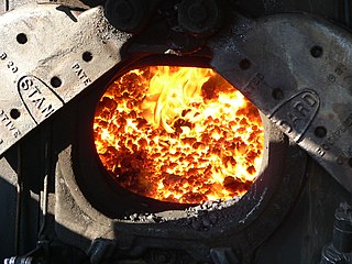 The firedoor into the firebox of a steam locomotive. The firebox peak temperature is approximately 2,500 °F (1,370 °C) |
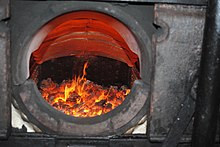
Steam locomotive fire tube firebox edit

In the standard steam locomotive fire-tube boiler, the firebox is surrounded by water space on five sides. The bottom of the firebox is open to atmospheric pressure, but covered by fire grates (solid fuel) or a firing pan (liquid fuel). If the engine burns solid fuel, like wood or coal, there is a grate covering most of the bottom of the firebox to hold the fire. An ashpan, mounted underneath the firebox and below the grates, catches and collects hot embers, ashes, and other solid combustion waste as it falls through the grates. In a coal-burning locomotive, the grates may be shaken to clean dead ash from the bottom of the fire. They are shaken either manually or (in larger locomotives) by a powered grate shaker. Wood-burning locomotives have fixed grates that cannot be shaken. Wood ash is generally powder which will fall through the grates with no more agitation required than the vibrations of the locomotive rolling down the track. The fire grates must be replaced periodically due to the extreme heat they must endure. Combustion air (primary air) enters through the bottom of the firebox and airflow is usually controlled by damper doors above the ash collection pocket of the ash pan. A locomotive that burns liquid fuel - usually "Bunker C" fuel oil or similar heavy oil - does not have grates. Instead, they have a heavy metal gauge firing pan bolted tight against the bottom of the firebox. The firing pan is covered with firebrick and the firebox has a firebrick lining, usually up to the level of the firebox door, all the way around the firebox. The oil burner is a nozzle containing a slot for the oil to flow out onto a steam jet which atomizes the oil into a fine mist which ignites in the firebox. The oil burner nozzle is usually mounted in the front of the firebox, protected by a hood of firebrick, and aimed at the firebrick wall below the firebox door. Dampers control air flow to the oil fire.

Brick arch edit

There is a large brick arch (made from fire brick) attached to the front wall (boiler throat plate) of the firebox immediately beneath the firetubes. This extends backwards over the front third to half of the firebed. It is supported on arch tubes, thermic syphons, or circulators. The brick arch directs heat, flames, and smoke back over the fire towards the rear of the firebox. Visible smoke contains unburned combustible carbon particles and combustible gasses. The purpose of this redirection is to cause more complete combustion of these particles and gasses which make the locomotive more efficient and causes less visible smoke to be emitted from the stack. Without the arch, flames and visible smoke would be sucked straight into the firetubes without having been fully burned, causing visible smoke to be emitted at the stack. The invention of the brick arch allowed locomotives to burn cheaper coal (which contains volatiles) instead of coke, it having been a legal requirement from the outset for engines to "consume their own smoke". The brick arch and its supports (arch tubes, thermic syphons, and circulators) require periodic replacement due to the extreme heat they endure. The brick arch also deflects "cold" air being drawn in through the firebox door from directly hitting the rear tube plate of the boiler and cooling it when the boiler is hot.
Firetubes edit
Firetubes are attached to one wall of the firebox (the front wall for a longitudinal boiler, the top for a vertical boiler) and carry the hot gaseous products of combustion through the boiler water, heating it, before they escape to the atmosphere. Firetubes serve the additional purpose of staying the flat tube (flue) sheets (front and rear) so that only the top of the front flue sheet and the bottom of the rear flue sheet must be separately braced.
Sheets and stays edit

The metal walls of the firebox are normally called sheets, which are separated and supported by stays. The stays support and brace the "sheets" (plates) against pressure. Ideally, they should be located at right angles to the sheets, but since the outer sheet (wrapper sheet) is often rounded and the top of the firebox (crown sheet) is relatively flat by comparison, such a relationship to both sheets is impossible. The actual location of the stays is a compromise. Since stay breakage is hidden, the stays have longitudinal holes, called tell-tales, drilled in them which will blow water and steam, revealing if they are broken. A boiler with more than 5 broken stays, or two next to each other, must be taken out of service and the stays replaced. The fusible plugs, usually located in the highest part of the crown sheet, have a soft metal alloy core which melts out if the water level in the boiler gets too low. Steam and water blowing into the firebox both alerts the locomotive crew to the low water condition and helps put out the fire. Not all locomotives are equipped with fusible plugs. Also, fusible plugs should be replaced at regular intervals, about every three months for a locomotive in regular service, because the soft metal alloy core will slowly melt out over time even if the boiler water is carried at proper levels. The "mudholes," or washout plugs, allow access to the interior of the boiler for washing and scraping away boiler mud and scale.
The sheets on the left and right are called "side sheets" while the sheet in the front of the firebox is the flue sheet. The "front flue sheet" is in the front of the boiler and at the rear of the smokebox. The "rear sheet" is at the back of the firebox and has the door opening in it. The crown sheet is the top of the firebox. The crown sheet must be covered by water at all times. If the water level drops below the crown sheet, it will become overheated and start to melt and deform, usually sagging between the crown stays. If the condition continues, the crown sheet will eventually be forced off the crown stays by the pressure in the boiler, resulting in a boiler explosion. This condition, usually caused by human error or inattention, is the single greatest cause of a locomotive boiler explosion.[citation needed]
Belpaire firebox edit
Normally the top of the boiler (wrapper sheet) over the firebox is radial to match the contour of the boiler; however, due to the problem of placing stays at right angles to both the wrapper sheet and the crown sheet (see above) the Belpaire firebox was developed. In the Belpaire design, the wrapper sheet is roughly parallel with the firebox sheets to allow better placement of the stays. This arrangement gives the firebox end of the boiler a more square shape and is usually made as large as possible within the loading gauge, to offer the greatest heating surface where the fire is hottest. The most notable user of the Belpaire firebox in the United States was the Pennsylvania Railroad. Other railroads, such as the Great Northern and Illinois Central, had locomotives with Belpaire fireboxes. Illinois Central 4-6-0 #382, Casey Jones' engine, had a Belpaire firebox. Steam is usually collected at the front corners of a Belpaire firebox, allowing for a domeless boiler. The top of the firebox, rather than being horizontal, is visibly higher at the front than at the rear to reduce the risk of water being carried over with the steam.
Wootten firebox edit
The Wootten firebox was very tall and wide to allow combustion of anthracite coal waste. Its size necessitated unusual placement of the crew, examples being camelback locomotives.
Combustion chamber edit

Some fireboxes were equipped with a so-called combustion chamber, this is a distinct component from the firebox and tubes - a large single extension of the firebox space, into the boiler barrel, and above the brick arch and separated from the grate and the fire bed, this placed additional space between the fire and the rear fire tube/flue sheet.
This allowed more complete combustion (reducing fuel wastage) and increased firebox surface area for greater heat-transfer, these factors Improved both boiler efficiency and fuel economy. The improved combustion (which reduces carbon-soot ejection) reduced the carry over of ash and soot into the fire-tubes and smoke box, reducing the frequency of cleaning required. Soot buildup and scale buildup (on the water side) severely reduce heat transfer through the fire tubes/flues, reducing steam generation and boiler efficiency.
Buildup of soot and scale can also lead to overheating and subsequent tube failure if not cleaned properly to remove soot (with water, compressed air and cleaning rods) and scale with boiler washouts and water treatment e.g. Porta Treatment (minimizes and virtually prevents scale buildup) is named after the Argentine locomotive engineer Livio Dante Porta, who invented it.
Fireman's duties edit
The fireman's role on a steam locomotive is to ensure the driver has an adequate supply of steam at his disposal at all times. This is achieved by maintaining a supply of fuel to the fire, monitoring the smoke from the fire and controlling it by the use of primary air through the fire bed/grate and secondary air through the firebox door and maintaining the boiler water level by use of steam injectors so that it covers the firebox crown sheet at all times – otherwise, the latter will overheat and weaken, and a boiler explosion may result. The fireman also assists the driver by spotting signals and keeping a good look out when not attending to the boiler. At the shed after the day's work is done, the fireman will fill the boiler with water and either bank or dump the fire (i.e. extinguish the fire) or leave the fire to die back according to company policy, apply the locomotive handbrake and if required chock the driver wheels to prevent the locomotive from moving while it is unattended.[3]
Gallery edit
-
 The flat sides and square corners show the shape of the Belpaire firebox. This offers a greater heating surface, increasing the efficiency of the engine
 -
 Locomotive with a normal firebox. The round top of the firebox makes attaching the boiler easier
 -
 The Wootten firebox can be seen as the large construction just in front of the tender. Note the unusual position of the driver's cab. The fireman was left exposed between firebox and tender


Road locomotive firebox edit
Road locomotives, such as traction engines, usually had fireboxes similar to those on railway locomotives but there were exceptions, e.g. the Sentinel steam waggon which had a vertical water tube boiler.
Stationary boiler firebox edit
There were, and are, many different designs of firebox for stationary boilers. In flue-type boilers (e.g. the Lancashire boiler) the flues themselves form the firebox. In water-tube boilers, the firebox is usually a firebrick-lined compartment below the water tubes.
Marine boiler firebox edit
In marine boilers there are also various types of firebox. The main distinction is, again, between fire-tube types (e.g. the Scotch boiler, with internal firebox) and water-tube types (e.g. the Yarrow boiler, with external firebox).
See also edit
References edit
- ^ John Daniel (April 16, 2013). "Basic features of a steam locomotive". Part 4 - Firebox layout. The Great Western Archive. Retrieved 10 September 2015.
- ^ Steam Trains In Knoxville, Tennessee (2015). "Parts of the Steam Locomotive". How a Steam Engine Works. Three Rivers Rambler. Retrieved 10 September 2015.
- ^ Smithsonian Institution, America on the Move Archived 2009-04-27 at the Wayback Machine.