


Summary
The flatrod system (German: Kunstgestänge, Stangenkunst, Stangenwerk, or Stangenleitung; Swedish: Konstgång or Stånggång) was an invention of the mining industry that enabled the mechanical movement generated by a water wheel (German: Kunstrad) to be transferred over short distances.[1] It was invented in the 16th century and by the 18th century was being used to transmit power up to four kilometres.[2] Flatrod systems were widely used in the Harz and Ore Mountains of Germany as well as in Cornwall, England and Bergslagen in Sweden.
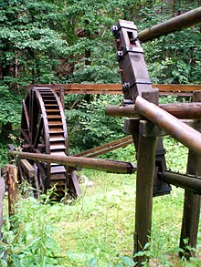
A replica of a flatrod system may be seen in Bad Kösen in Germany on the River Saale[3] and there is a replica water wheel, used to drive flatrods, in Clausthal-Zellerfeld in the Upper Harz, formerly the biggest mining region in Europe.
Fundamentals edit
The flatrod system dates to the period before the invention of the steam engine and electricity. Using flatrods it was possible to operate man engines and pumping systems, even though the water wheel in question had a rotary, not a reciprocal, motion. So that the rods could be made to move in a reciprocal fashion, a change of direction had to be achieved by means of specially shaped components.[4] The components of the system that were mounted in the mining shaft were called shaft rods (Schachtgestänge) or pump rods (Hubgestänge). Systems mounted in drift mines were called drift rods (Streckengestänge).[5]
The flatrods (Feldgestänge) themselves were used to transfer power over greater distances between the main engine and the pump rods.[4] Iron collars (Kunstringe) were fitted onto the wheel axles, connecting pipes (Ansetzröhren) and metal sleeves (Ansteckkielen) as well as certain parts of the wooden flatrods. The actual rods (Kunststangen) were long squared timbers that transmitted the power horizontally or at an incline. They had articulated iron joints (Kunstschlösser or Stangenschlösser) that were designed such that they could be interleaved into one another and secured with bolts or screws.[6]
Lifting rods edit
The lifting rod system ran vertically up the mineshaft, either to transfer power to the individual sets of shaft pumps (when they were known as pump rods) or, in the case of man engines, to operate the man engine rods. In some cases the lifting rod system performed both duties. It consisted of roughly 19 to 20 centimetre thick squared spruce timbers. The poles were dovetailed at the ends and sides and were fixed to one another with correspondingly mortised wooden joints (Holzlaschen). These joints were tightly bound to the ends of the lifting rods with iron collars. In addition the iron collars were prevented from slipping by bolts inserted through them. At set distances there were also hooks on the sides that were used to hang the piston rods (Kolbenstangen). So that the horizontal movement of the flat rods could be turned into a vertical movement, a rotating cross-shaped lever (Kunstkreuz) was fitted to the lifting rods. Connexion to the cross lever was achieved using a crank (Kunstschloss). To balance the load it was usual to have two lifting rods.[4]
Flatrods edit


The purpose of the flatrods was to transfer the power of the motive engine over greater distances to the pump rods in the shaft. This was necessary if the motive engine could not be mounted above or immediately next to the mine shaft. A flatrod system had the disadvantage that there were additional efficiency losses due to the greater masses that had to be moved. The reciprocal motion in the joints (Schlösser) of the interconnected flatrods led to lifting losses of from 25 to 50 percent.[7] In addition the construction of flatrods required additional timber. This was very maintenance-intensive due to the effects of weathering and it needed additional staff to inspect and maintain the flatrods.
The flatrods consisted of several wooden rods, fitted with iron hinges. At the ends of the rods, on either side, were so-called Kunstschlösser. These were cut to fit in such a way that one rod could be mortised into another. This was necessary so that the flatrods could not slide apart as a result of to-and-fro or up-and-down motion.[1]
There were two types of flatrod: flatrods with rollers and flatrods with oscillating cranks (Schwingen). The former were laid on rollers. The rollers consisted of round timbers about eight to ten inches thick, that were firmly set into the ground on their underside and fixed in place with braces. In order to minimise friction, the rod was fitted with a drag rail (Schleppschiene) in the area of the individual rollers that was made of beechwood and long enough to for the entire stroke length.[7]
References edit
- ^ a b Bergmännisches Wörterbuch. Bey Johann Christoph Stößel, Chemnitz 1778
- ^ Stronger Than a Hundred Men: A History of the Vertical Water Wheel Terry S. Reynolds 1983
- ^ Blaues Band durch Sachsen-Anhalt: Bad Kösen
- ^ a b c Franz Adolf Fürer: Salzbergbau und Salinenkunde. Druck und Verlag von Friedrich Vieweg und Sohn, Braunschweig 1900
- ^ Bericht vom Bergbau. Bey Siegfried Leberecht Crusius, Leipzig 1772
- ^ Carl Friedrich Richter: Neuestes Berg-und Hütten-Lexikon. Erster Band, Kleefeldsche Buchhandlung, Leipzig 1805
- ^ a b Joh. Jos. Prechtl (ed.): Technologische Encyklopädie oder alphabetisches Handbuch der Technologie, der technischen Chemie und des Maschinenwesens. Fünfter Band, Verlag der J. G. Gotta'schen Buchhandlung, Stuttgart, 1834
External links edit
- The Mechanical Transmission of Power (1): Stangenkunst
- Das Huttaler Wasserregal Description of the water region in the Harz. GeoMuseum TU Clausthal