


Summary
Nuclear gas-core-reactor rockets can provide much higher specific impulse than solid core nuclear rockets because their temperature limitations are in the nozzle and core wall structural temperatures, which are distanced from the hottest regions of the gas core. Consequently, nuclear gas core reactors can provide much higher temperatures to the propellant. Solid core nuclear thermal rockets can develop higher specific impulse than conventional chemical rockets due to the low molecular weight of a hydrogen propellant, but their operating temperatures are limited by the maximum temperature of the solid core because the reactor's temperatures cannot rise above its components' lowest melting temperature.
Theory of operation edit
Nuclear gas-core-reactor rockets can provide much higher specific impulse than solid core nuclear rockets because their temperature limitations are in the nozzle and core wall structural temperatures, which are distanced from the hottest regions of the gas core. Consequently, nuclear gas core reactors can provide much higher temperatures to the propellant. Solid core nuclear thermal rockets can develop higher specific impulse than conventional chemical rockets due to the low molecular weight of a hydrogen propellant, but their operating temperatures are limited by the maximum temperature of the solid core because the reactor's temperatures cannot rise above its components' lowest melting temperature.
Due to the much higher temperatures achievable by the gaseous core design, it can deliver higher specific impulse and thrust than most other conventional nuclear designs. This translates into shorter mission transit times for future astronauts or larger payload fractions. It may also be possible to use partially ionized plasma from the gas core to generate electricity magnetohydrodynamically, subsequently negating the need for an additional power supply.
General features of the nuclear reactor edit
All gas-core reactor rocket designs share several properties in their nuclear reactor cores, and most designs share the same materials. The closest terrestrial design concept is the gaseous fission reactor.
Nuclear fuel edit
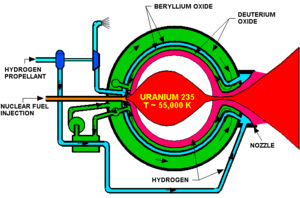
The fissile fuel is usually highly enriched uranium pellets or a uranium containing gas (U-235 or U-233). Sometimes uranium tetrafluoride is required due to its chemical stability; the propellant is usually hydrogen.
Neutron moderator edit
Most gas core reactors are surrounded by a radial first wall capable of taking the brunt of the extreme environment present inside the core, a pressure shell to hold everything together, and a radial neutron moderator usually made up of beryllium oxide. The propellant also provides moderation.
Reactor coolant / Rocket propellant edit
The hydrogen propellant cools the reactor and its various structural parts. Hydrogen is first pumped through the nozzle, then through the walls and back down through the core region. Once it passes through the core region, the hydrogen is exhausted. If cooling from the propellant is not enough, external radiators are required. The internal gas core temperatures in most designs vary, but the designs with the highest specific impulses generally have fissioning gas plasmas heating a low mass propellant. This heating occurs primarily through radiation.
Heat transfer edit
At high temperatures, heat is transferred predominantly by thermal radiation (rather than thermal conduction). However, the hydrogen gas used as propellant is almost completely transparent to this radiation. Therefore, in most gas core reactor rocket concepts, some sort of seeding of the propellant by opaque solid or liquid particles is considered necessary. Particles of carbon [soot] (which is highly opaque and remains solid up to 3915 K, its sublimation point) would seem to be a natural choice; however, carbon is chemically unstable in a hydrogen-rich environment at high temperatures and pressures. Thus, rather than carbon, dust particles or liquid droplets of a material such as tungsten (melting point 3695 K, boiling point 6203 K) or tantalum hafnium carbide (melting point 4263 K, boiling point some unknown higher temperature) are preferred. These particles would make up up to 4% of the mass of the exhaust gas, which would considerably increase the cost of propellant and slightly lower the rocket's specific impulse.
At the temperatures necessary to reach a specific impulse of 5000-7000 s, however, no solid or liquid material would survive (the required reactor temperature would be at least 50,000–100,000 K), and the propellant would become transparent; as a result, most of the heat would be absorbed by the chamber walls. This would preclude the use of a nuclear thermal rocket with this high of a specific impulse, unless some other means of seeding or heat transfer to the propellant is found.
Control edit
Control can be accomplished by either changing the relative or overall densities of the fissile fuel and the propellant or by having outside control drives moving neutron absorbing drums or the radial moderator.
Open cycle versus closed cycle edit
There are two main variations of the gas core reactor rocket: open cycle designs, which do not contain the fuel within a vessel, and closed cycle designs, which contain the gas reaction core within a solid structure.
Open cycle designs edit
The disadvantage of the open cycle is that the fuel can escape with the working fluid through the nozzle before it reaches significant burn-up levels. Thus, finding a way to limit the loss of fuel is required for open-cycle designs. Unless an outside force is relied upon (i.e. magnetic forces, rocket acceleration), the only way to limit fuel-propellant mixing, is through flow hydrodynamics. Another problem is that the radioactive efflux from the nozzle makes the design totally unsuitable for operation within Earth's atmosphere.
The advantage of the open cycle design is that it can attain much higher operating temperatures than the closed cycle design, and does not require the exotic materials needed for a suitable closed cycle design.
Flow hydrodynamics in open cycle designs edit
The shape of the fissile gas core can be either cylindrical, toroidal, or counter flow toroidal. Since there are issues regarding the loss of fissile fuel with the cylindrical and toroidal designs, the counter-flow toroidal gas core geometry is the primary source of research. The counter flow toroid is the most promising because it has the best stability and theoretically prevents mixing of the fissile fuel and propellant more effectively than the aforementioned concepts. In this design, the fissile fuel is kept mostly in a base injection stabilized recirculation bubble by hydrodynamic confinement. Most designs utilize a cylindrical gas core wall for ease of modeling. However, previous cold flow tests have shown that hydrodynamic containment is more easily achieved with a spherical internal wall geometry design.
The formation of the fuel vortex is complex. It basically comes down to flow over a projectile shape with a blunt base. The vortex is formed by placing a semi-porous wall in front of the desired location of the fuel vortex but leaves room along its sides for hydrogen propellant. Propellant is then pumped inside the reactor cavity along an annular inlet region. A dead space then develops behind the semi-porous wall; due to viscous and shear forces, a counter toroidal rotation develops. Once the vortex develops, fissile fuel can be injected through the semi-porous plate to bring the reactor critical. The formation and location of the fuel vortex now depends on the amount of fissile fuel that bleeds into the system through the semi-porous wall. When more fuel bleeds into the system through the wall, the vortex moves farther downstream. When less bleeds through, the vortex moves farther upstream. Of course, the upstream location is constrained by the placement of the semi-porous wall.
Closed cycle designs edit

The closed cycle is advantageous because its design virtually eliminates loss of fuel, but the necessity of a physical wall between the fuel and the propellant leads to the obstacle of finding a material with extremely optimized characteristics. One must find a medium that is transparent to a wide range of gamma energies, but can withstand the radiation environment present in the reactor, specifically particle bombardment from the nearby fission reactions. This barrage of particles can lead to sputtering and eventual wall erosion.
One closed cycle gas core rocket design (often called the nuclear lightbulb) contains the fissioning gas in a quartz enclosure that is separate from the propellant. First, the hydrogen coolant runs through the nozzle and inside the walls of the quartz enclosure for cooling. Next, the coolant is run along the outside of the quartz fuel enclosure. Since the fissile gas would be directly in contact with the walls, the operating temperature is not as great as other designs because the walls would eventually ablate away.
Magnetic confinement edit
Barring an external force, hydrodynamic containment is the only way to increase the residence time of the fuel in the reactor. However, one may ask why bar an outside force, could not magnetic confinement be used since the fuel would be highly ionized (three or four times ionized) while the propellant is only partially ionized? To answer this question one must understand a little about magnetic plasma confinement. The key parameter of interest for magnetic confinement is the ratio of kinetic pressure to magnetic pressure, β.
When β<1 magnetic confinement is possible (most fusion schemes have a β close to 0.05). However, the pressures in a gas core rocket are much higher than pressures in fusion devices, approximately 1000 atm (100 MPa). For these pressures, the necessary magnetic field strength required is close to 16 teslas just to produce β=1. For a magnetic field of this magnitude, superconducting technology is necessary and the added mass of such a system would be detrimental. Also, even with a β<1, resistive diffusion will cause the fuel core to collapse almost immediately unless β<<1, which would require an even larger magnetic field.
However, because the propellant and fuel can be at the same pressure, a magnetic field could retain the fuel merely by impeding convective mixing with the propellant, and would play no role in maintaining pressure in the reactor chamber: The pressure of the fuel is not relevant to a calculation of β. Because the situation is entirely unlike that of the confinement of a fusion plasma in vacuum, the required strength of a magnetic field for fission fuel retention must be estimated based on magnetohydrodynamic considerations (in particular, the suppression of turbulent mixing).
Impact of rocket acceleration edit
Another important aspect to GCRs is the impact of the rocket acceleration on the containment of the fuel in the fuel bubble. A rocket acceleration of only 0.001 g (10 mm/s²) will cause buoyancy effects to decrease core containment by 35% if all other flow-rates are held constant from a zero g startup. Ultimately, the fuel-propellant flows will have to be throttled until the rocket approaches some sort of steady state.
Neutronic considerations edit
Since steep temperature gradients will be present in any such gas core reactor, several implications for neutronics must be considered. The open-cycle gas-core reactor (OCGCR) is typically a thermal/epithermal reactor. Most types of OCGCR require external moderation due to the steep temperature gradients inside the gaseous core. Neutrons born in the fuel region travel relatively unimpeded to the external moderator where some are thermalized and sent back into the gas core. Due to the high core temperatures, however, on the return trip the neutrons are up scattered in the fuel region, which leads to a significant negative reactor worth. To achieve criticality, this reactor is operated at very high pressure and the exterior radial wall is made up of a moderator of some sort, generally beryllium oxide. Moderation can also come from introducing moderating particles into either the fuel or propellant streams, but by doing so, the benefits in neutronics is canceled by loss of rocket performance.
Technology summary and outlook edit
The open-cycle gas-core rocket has many unique design attributes that make it a serious challenger to other proposed propulsion for interplanetary missions. Due to the necessity of having a transparent wall inside the reactor for a closed cycle concept, the benefit of moving to a gas core from a solid core are nearly negated. The high specific impulse and large thrust possible for the OCGCR correspond to shorter mission times and higher payload fractions. However, the technical challenges and unknowns inherent in its design are many. Additionally, any test of the system performed on earth would be under a gravity field of 1 g, which would bring buoyancy effects into play inside the gaseous core.
Due to the inability to perform live testing on earth, research is focused primarily on computational modeling of such a system. It was previously mentioned that the specific impulse could be as high as or higher than 3000 s. However, results of computational modeling point towards this number being somewhat optimistic. When thermal hydraulics were modeled more completely for a typical base injection stabilized recirculation bubble gas core rocket by D. Poston, the specific impulse dropped from >3000 s to <1500 s. In the base injection stabilized recirculation bubble gas core rocket concept, it is thought that some additional method of fuel confinement will be beneficial. As mentioned earlier, relying completely on magnetic containment of the fuel bubble is not yet practical. However, a magnetic field may be able to assist in containment or help suppress turbulence that would lead to fuel-propellant mixing.
The primary areas of future research for such an OCGCR would therefore be centered on keeping the fuel and propellant from mixing as much as possible. Although this article has focused on enriched uranium for the fuel and hydrogen for the propellant, this may not be the optimal choice for either. Other fuels, such as plutonium, and other propellants, including helium or even helium-3, have also been considered and in certain situations provide advantages.
See also edit
References edit
- Thode, L. E.; Cline, M. C.; Howe, S. D. (July 1998). "Vortex Formation and Stability in a Scaled Gas-Core Nuclear Rocket Configuration". Journal of Propulsion and Power. 14 (4): 530–536. doi:10.2514/2.5310.
- Poston, David I.; Kammash, Terry (January 1996). "A Computational Model for an Open-Cycle Gas Core Nuclear Rocket". Nuclear Science and Engineering. 122 (1): 32–54. Bibcode:1996NSE...122...32P. doi:10.13182/NSE96-A28546. OSTI 201333.
- Sforza, P.M.; Cresci, R.J. (31 May 1997). Fuel efficient hydrodynamic containment for gas core fission reactor rocket propulsion (Report). doi:10.2172/510312. OSTI 510312.
- Innovative Nuclear Space Power and Propulsion Institute. (accessed last: 4/16/04). Gas Core Reactors. [Online] available: https://web.archive.org/web/20051115182102/http://www.inspi.ufl.edu/research/gcr/index.html
- Steve Howe, Nuclear Rocket Technologies. Online copy available: Web archive, 2008
- Sahu, Jubaraj; Nietubicz, Charles J.; Steger, Joseph L. (September 1985). "Navier-Stokes computations of projectile base flow with and without mass injection". AIAA Journal. 23 (9): 1348–1355. Bibcode:1985AIAAJ..23.1348S. doi:10.2514/3.9091.
- Koroteev, Anatoly; Son, Edward (8 January 2007). "Development Nuclear Gas Core Reactor in Russia" (PDF). 45th AIAA Aerospace Sciences Meeting and Exhibit. doi:10.2514/6.2007-35. ISBN 978-1-62410-012-3. Archived from the original (PDF) on 30 September 2007. Retrieved 11 October 2017.
- Bussard, R.W., DeLauer, R. D. (1965), Fundamentals of Nuclear Flight, McGraw-Hill, ISBN 0-07-009300-8
External links edit
- Opening the Next Frontier by Anthony Tate, archive copy of nuclearspace.com website
- A Summary of Generation IV Non-Classical Nuclear Systems // Generation IV Roadmap Session II, ANS Winter Meeting Reno, NV, November 13, 2001