


Summary
The Godavari Arch Bridge is a bowstring-girder bridge that spans the Godavari River in Rajahmundry, India. It is the latest of the three bridges that span the Godavari river at Rajahmundry. The Havelock Bridge being the earliest, was built in 1897, and having served its full utility, was decommissioned in 1997. [1][2] The second bridge known as the Godavari Bridge is a truss bridge and is India's third longest road-cum-rail bridge crossing a water body.[1][3][4][5]
Godavari Arch Bridge | |
|---|---|
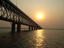
 The Godavari Arch Bridge in Rajahmundry | |
| Coordinates | 17°00′28.2″N 81°45′21″E / 17.007833°N 81.75583°E |
| Carries | Single Railway lane |
| Crosses | Godavari River |
| Locale | Rajahmundry, Andhra Pradesh |
| Other name(s) | Rajahmundry-Kovvur Bridge |
| Owner | Indian Railways |
| Maintained by | Indian Railways |
| Preceded by | Godavari Bridge |
| Characteristics | |
| Design | Bowstring-Girder |
| Total length | 2,745 metres (9,006 ft) |
| Longest span | 97.552 metres (320 ft) |
| No. of spans | 28 twin arches |
| Piers in water | 28 |
| History | |
| Designer | Hindustan Construction Company |
| Constructed by | Hindustan Construction Company |
| Construction start | 1991 |
| Construction end | 1997 |
| Opened | March 12, 1997 |
| Replaces | Havelock Bridge |
| Location | |
 | |
The bridge is one of the longest span prestressed concrete arch bridges in Asia.[5] The Indian Railways who built this bridge have stated that "It is perhaps for the first time anywhere in the world that a bowstring arch girder using concrete has been constructed for such a long span of 97.55 metres (320.0 ft), and that too for the Railway loading."[1] It has been widely used to represent Rajahmundry in arts, media, and culture. It is one of the recognised symbols of Rajahmundry.
Geography edit
The bridge is built across the Godavari River, the largest river in South India at over 1,000 metres (0.62 mi) length. It is built in the region as the river enters into the deltaic reach before discharging into the sea 60 kilometres (37 mi) downstream of the bridge. At the location of the bridge the Godavari river flows with a width of about 3 kilometres (1.9 mi), split in two channels with an island formation in between. The maximum discharge observed in the river is reported to be around 3 million m3/s and the maximum velocity of water flow as 5 metres (16 ft) per second.[1] The bridge is located in a cyclonic area where the wind speed touch 200 kilometres (120 mi) per hour.
The bridge is located in two channels, the Kovvur channel and the Rajahmundry channel, and hence the bridge is also known as the Kovvur-Rajahmundry Bridge. The Rajahmundry channel has a deep rocky bed, and even the water level is 18–20 metres (59–66 ft). Comparatively the Kovur channel is shallow with a water depth of about 8–10 metres (26–33 ft) and riverbed is made up of clay deposits.
History edit
Earlier Bridges edit

This bridge is the third in the series of the bridges that spans the Godavari river at Rajahmundry. The earliest bridge is the Havelock bridge, which was built in 1897 by Frederick Thomas Granville Walton. It is 2,950 metres (9,680 ft) long and is made of masonry piers and steel girders.[1] It was decommissioned in 1997 as it had served its full utility. The Godavari Arch bridge was actually built to replace the Havelock bridge. Additionally, the Godavari Arch bridge is aligned parallel to the Old Godavari bridge, and is separated by a short distance of about 200 meters.
The second bridge is a railroad bridge, the Godavari bridge, built in the 1960s as a part of doubling of railway track between Chennai – Howrah. This is a truss bridge, with the superstructure made of steel. It is in active service and carries a single railway track in the lower level, and two-way road, pedestrian pathways on the upper level. Initial plans for the construction of the Godavari Arch bridge consisted of a steel superstructure like the Godavari bridge. But later the concept of prestressed concrete girders was considered, and subsequently the designing was continued with the concrete girders.[1][6]
Planning edit
Godavari Arch Bridge was to be built to replace and the Havelock Bridge, which had served its full utility. Initial plans made for the bridge considered a superstructure made of steel. But, as the usage of concrete as construction material had become popular since its introduction in the 1930s, the issue of type of superstructure was re–examined by the Indian Railways. It was decided to examine the possibility of evolving a prestressed concrete bridge with a 97.55 metres (320.0 ft) span. Firms were pre-qualified for the purpose with preferred options suggested for submission of offers, and for the preference of steel girder or concrete girder.
Among the three firms which were shortlisted to submit proposals, two firms opted for concrete bridge and one for steel bridge. On the basis of these proposals, the authorities at Indian Railways prepared the Terms of Reference prescribing the design criteria. Following this, the three qualified firms, the Research Design and Standards Organization and the Railway Board were taken into consideration to indicate their views and comments on the Terms of Reference. And, subsequently the design criteria for the bridge was finalised.
The proposals received from the three firms were examined by Proof Consultants who recommended that the design offered by Hindustan Construction Company be accepted. It proposed the bowstring-girder type concrete arch of span 92.552 metres (303.65 ft) with prestressed concrete box girder to act as the tie. Following this recommendation, the proposal of Hindustan Construction Company was accepted considering its technical feasibility and financial viability. Hindustan Construction Company won the order to plan, design and build the bridge.[1]
Construction edit
The bridge, built by the Hindustan Construction Company, for the Indian Railways, was designed by Bureau BBR, Switzerland, and checked by Leonardt Andrä and Partners, Germany.[3][6] Construction on the bridge began in 1991 and lasted till 1997. It was commissioned for passenger traffic in March 1997 and became fully operational for running trains by the Indian Railways from 2003.[5]
Description edit
Specifications edit
The twin arches, box girders, struts are all made of prestressed concrete.
The twin arches have a constant width of 0.8 metres (2 ft 7 in) and depth varying from 1.7 metres (5 ft 7 in) at the springing to 1.1 metres (3 ft 7 in) at the crown. These are connected laterally with struts (known as Vierendeel truss) and box girder.
There are 28 identical spans of twin arches, of parabolic profile, spaced at 5.6 metres (18 ft), each of 97 metres (318 ft) width from centre to centre of the piers with a total length of 2.7 kilometres (1.7 mi).[3]
The effective span from centre to centre of the bearings is 94 metres (308 ft).[5]
Each girder is 95.552 metres (313.49 ft) long.
The final dimensions of the box girder are 95.462 metres (313.20 ft)×5,200 millimetres (200 in) (bottom) with thickness of the top slab of 296 millimetres (11.7 in), the web of 300 millimetres (12 in) thickness and with the bottom slab thickness kept at 240 millimetres (9.4 in).A diaphragm stiffens the box girder at each Dina Hanger location.[6]
The substructure of the bridge consists of 28 piers.[7]
Design aspects edit
The superstructure of the bridge is of the bow-string girder type. While designing, the projected speed for the trains was taken as 160 km per hour. Taking into consideration the cyclonic conditions, the wind speed considered without live load was 200 kilometres (120 mi) per hour, and with dead load the speed considered was 158 kilometres (98 mi) per hour. As the location of the bridge is in the Seismic Zone I, seismic load has not been accounted for in the design.
The bridge is designed to run trains at a speed of 160 miles (260 km) per hour and is designed to withstand wind speed of 200 miles (320 km) per hour during cyclonic storms that are anticipated in and around Rajahmundry.[5]
Arches edit
The arches are designed to share 80% of the dead load and live load transferred from the hangers and thus a plays a critical role of relieving the flexural and shear stresses on the girder. Twelve sinking supports are provided at each hanger location connecting with the girder.[6]
Hangers edit
Each span of the bridge has 24 hangers, which are further divided into six types depending on their length. Each Dina Hanger is made of 49 high tensile steel wires of 7 millimetres (0.28 in) diameter each. These wires run parallel to each other and are encased in a high tensile polythene pipe, which is cement grouted.[8]
Girders edit
The box girders are made of M42 grade concrete. Each girder was prestressed with 16 longitudinal cables, which in turn were prestressed to a force of 2950 kN each.[1]
The box girder, which functions as the deck of the bridge and carries the live load, comprises end diaphragm (1,000 millimetres (39 in) thick), which has inspection windows.[9]
The design of the girder accounts for loading conditions of full span train load, half span train load, one third span train load and so forth with due accounting of temperature variation of ±10 °C (50 °F). At each stage of casting of the girders (seven stages of casting were involved for each girder from girder stressing to removal of form work) forces generated in the arch section were studied and accounted. The girder casting also ensured that no cracks appeared in the arches at any stage.[10]
Bearings edit
The bridge has been provided with pot bearings, of 1050 tonnes capacity. One each pier, the girder is supported on four pot bearings of three types: PNa, PNe, PN.
The PNa type bearing (which facilitates free sliding in both directions) on one pier and PNe type (slides only in one direction) in the succeeding pier and PN type which is fixed type.
The PNa and PNe type of bearings have been pre-set for 60 millimetres (2.4 in) movement in the longitudinal direction and 10 millimetres (0.39 in) in the lateral direction and the centre line of top plate has been fixed relatively by 60 millimetres (2.4 in)/10 millimetres (0.39 in) with respect to centre line of bottom plate of the bearing which will permit the movements due to creep, shrinkage and elastic deformation.[7] Their placement ensures that only longitudinal movement takes place without permitting any lateral moment.[11]
Three sets of bearings were imported from Switzerland, while the balance bearings were made by BBR (India) Pvt Ltd, India.[1]
Maintenance edit
Corrective action edit
After the bridge was constructed, the railway authorities carried out settlement studies of all 28 piers in view of the foundation conditions on which they were founded. These measurements indicated that pier settlement in only one pier, namely "pier 27" in the Kovvur Channel was of the order of 211 millimetres (8.3 in), which needed corrective action, while in all other piers the settlement was less than 75 millimetres (3.0 in) indicating that pier foundations had settled down. Since the rotation in the vertical plane exceeded the prescribed value for differential settlement, BBR, consultants to Hindustan Construction Company (HCC), anticipated that the top plate of the bearing is "likely touch the bottom plate thereby damaging the bearing." To remedy the situation, the consultant advised HCC, to maintain a uniform gradient of 200 millimetres (7.9 in) between the piers 26, 27 and 28. However, the lifting of bearings by 200 millimetres (7.9 in) was executed during the month of May 2003, even though the settlement of the pier in question was not significant after May 2002. This was achieved by using Conbextra HES (which has properties of free flow, achieving high early strength and quick setting), a cementation material manufactured by M/s. FOSROC, India. The gap of 200 millimetres (7.9 in) between the pedestal top and bottom of bearing was filled with this material. This was done by careful planning of stopping train operations (by taking two breaks of short intervals) over the bridge during the period of rectification supported by eight 400 tonnes capacity hydraulic jacks with lock nut and shim plates’ arrangement.[7]
See also edit
References edit
- ^ a b c d e f g h i R.R.Bhandari. "Bridges: The Spectacular Feat of Indian Engineering" (PDF). Indian Railway Service of Mechanical Engineers. Archived from the original (PDF) on 5 March 2016. Retrieved 6 August 2012.
- ^ Khan, Mukram. "The Havelock Bridge Memorial Stone". Flickr. Archived from the original on 23 March 2014. Retrieved 1 August 2012.
- ^ a b c "Godavari Bridge". Structurae. Archived from the original on 5 August 2011. Retrieved 7 June 2011.
- ^ "Third Godavari Railway Bridge, India". Structurae. Archived from the original on 9 June 2013. Retrieved 7 June 2011.
- ^ a b c d e Dayaratnam, pp. 219–228
- ^ a b c d Dayaratnam, p. 219
- ^ a b c "Project Report on correction of Level Pier 27 of Godavari Bridge" (PDF). iricen.indianrailways.gov.in. Archived from the original (PDF) on 18 August 2011. Retrieved 8 June 2011.
- ^ Dayaratnam, p. 226
- ^ Dayaratnam, p. 220
- ^ Dayaratnam, pp. 224–226
- ^ Dayaratnam, p. 227
Bibliography edit
- P. Dayaratnam; Indian Institution of Bridge Engineers; Sinha. A.H. (2000). Cable stayed, supported, and suspension bridges. Universities Press. ISBN 978-81-7371-271-5. Retrieved 8 June 2011.
{{cite book}}:|work=ignored (help)