


Summary
In coding theory, Hamming(7,4) is a linear error-correcting code that encodes four bits of data into seven bits by adding three parity bits. It is a member of a larger family of Hamming codes, but the term Hamming code often refers to this specific code that Richard W. Hamming introduced in 1950. At the time, Hamming worked at Bell Telephone Laboratories and was frustrated with the error-prone punched card reader, which is why he started working on error-correcting codes.[1]
| Hamming(7,4)-code | |
|---|---|
 | |
| Named after | Richard W. Hamming |
| Classification | |
| Type | Linear block code |
| Block length | 7 |
| Message length | 4 |
| Rate | 4/7 ~ 0.571 |
| Distance | 3 |
| Alphabet size | 2 |
| Notation | [7,4,3]2-code |
| Properties | |
| perfect code | |

The Hamming code adds three additional check bits to every four data bits of the message. Hamming's (7,4) algorithm can correct any single-bit error, or detect all single-bit and two-bit errors. In other words, the minimal Hamming distance between any two correct codewords is 3, and received words can be correctly decoded if they are at a distance of at most one from the codeword that was transmitted by the sender. This means that for transmission medium situations where burst errors do not occur, Hamming's (7,4) code is effective (as the medium would have to be extremely noisy for two out of seven bits to be flipped).
In quantum information, the Hamming (7,4) is used as the base for the Steane code, a type of CSS code used for quantum error correction.
Goal edit
The goal of the Hamming codes is to create a set of parity bits that overlap so that a single-bit error in a data bit or a parity bit can be detected and corrected. While multiple overlaps can be created, the general method is presented in Hamming codes.
Bit # 1 2 3 4 5 6 7 Transmitted bit Yes No Yes No Yes No Yes No Yes Yes No No Yes Yes No No No Yes Yes Yes Yes


This table describes which parity bits cover which transmitted bits in the encoded word. For example, p2 provides an even parity for bits 2, 3, 6, and 7. It also details which transmitted bit is covered by which parity bit by reading the column. For example, d1 is covered by p1 and p2 but not p3 This table will have a striking resemblance to the parity-check matrix (H) in the next section.
Furthermore, if the parity columns in the above table were removed
Yes Yes No Yes Yes No Yes Yes No Yes Yes Yes
then resemblance to rows 1, 2, and 4 of the code generator matrix (G) below will also be evident.
So, by picking the parity bit coverage correctly, all errors with a Hamming distance of 1 can be detected and corrected, which is the point of using a Hamming code.
Hamming matrices edit
Hamming codes can be computed in linear algebra terms through matrices because Hamming codes are linear codes. For the purposes of Hamming codes, two Hamming matrices can be defined: the code generator matrix G and the parity-check matrix H:


As mentioned above, rows 1, 2, and 4 of G should look familiar as they map the data bits to their parity bits:
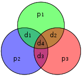
- p1 covers d1, d2, d4
- p2 covers d1, d3, d4
- p3 covers d2, d3, d4
The remaining rows (3, 5, 6, 7) map the data to their position in encoded form and there is only 1 in that row so it is an identical copy. In fact, these four rows are linearly independent and form the identity matrix (by design, not coincidence).
Also as mentioned above, the three rows of H should be familiar. These rows are used to compute the syndrome vector at the receiving end and if the syndrome vector is the null vector (all zeros) then the received word is error-free; if non-zero then the value indicates which bit has been flipped.
The four data bits — assembled as a vector p — is pre-multiplied by G (i.e., Gp) and taken modulo 2 to yield the encoded value that is transmitted. The original 4 data bits are converted to seven bits (hence the name "Hamming(7,4)") with three parity bits added to ensure even parity using the above data bit coverages. The first table above shows the mapping between each data and parity bit into its final bit position (1 through 7) but this can also be presented in a Venn diagram. The first diagram in this article shows three circles (one for each parity bit) and encloses data bits that each parity bit covers. The second diagram (shown to the right) is identical but, instead, the bit positions are marked.
For the remainder of this section, the following 4 bits (shown as a column vector) will be used as a running example:

Channel coding edit

Suppose we want to transmit this data (1011) over a noisy communications channel. Specifically, a binary symmetric channel meaning that error corruption does not favor either zero or one (it is symmetric in causing errors). Furthermore, all source vectors are assumed to be equiprobable. We take the product of G and p, with entries modulo 2, to determine the transmitted codeword x:

This means that 0110011 would be transmitted instead of transmitting 1011.
Programmers concerned about multiplication should observe that each row of the result is the least significant bit of the Population Count of set bits resulting from the row and column being Bitwise ANDed together rather than multiplied.
In the adjacent diagram, the seven bits of the encoded word are inserted into their respective locations; from inspection it is clear that the parity of the red, green, and blue circles are even:
- red circle has two 1's
- green circle has two 1's
- blue circle has four 1's
What will be shown shortly is that if, during transmission, a bit is flipped then the parity of two or all three circles will be incorrect and the errored bit can be determined (even if one of the parity bits) by knowing that the parity of all three of these circles should be even.
Parity check edit
If no error occurs during transmission, then the received codeword r is identical to the transmitted codeword x:

The receiver multiplies H and r to obtain the syndrome vector z, which indicates whether an error has occurred, and if so, for which codeword bit. Performing this multiplication (again, entries modulo 2):

Since the syndrome z is the null vector, the receiver can conclude that no error has occurred. This conclusion is based on the observation that when the data vector is multiplied by G, a change of basis occurs into a vector subspace that is the kernel of H. As long as nothing happens during transmission, r will remain in the kernel of H and the multiplication will yield the null vector.
Error correction edit
Otherwise, suppose, we can write

modulo 2, where ei is the unit vector, that is, a zero vector with a 1 in the , counting from 1.


Thus the above expression signifies a single bit error in the place.
Now, if we multiply this vector by H:

Since x is the transmitted data, it is without error, and as a result, the product of H and x is zero. Thus

Now, the product of H with the standard basis vector picks out that column of H, we know the error occurs in the place where this column of H occurs.
For example, suppose we have introduced a bit error on bit #5


The diagram to the right shows the bit error (shown in blue text) and the bad parity created (shown in red text) in the red and green circles. The bit error can be detected by computing the parity of the red, green, and blue circles. If a bad parity is detected then the data bit that overlaps only the bad parity circles is the bit with the error. In the above example, the red and green circles have bad parity so the bit corresponding to the intersection of red and green but not blue indicates the errored bit.
Now,

which corresponds to the fifth column of H. Furthermore, the general algorithm used (see Hamming code#General algorithm) was intentional in its construction so that the syndrome of 101 corresponds to the binary value of 5, which indicates the fifth bit was corrupted. Thus, an error has been detected in bit 5, and can be corrected (simply flip or negate its value):

This corrected received value indeed, now, matches the transmitted value x from above.
Decoding edit
Once the received vector has been determined to be error-free or corrected if an error occurred (assuming only zero or one bit errors are possible) then the received data needs to be decoded back into the original four bits.
First, define a matrix R:

Then the received value, pr, is equal to Rr. Using the running example from above

Multiple bit errors edit

It is not difficult to show that only single bit errors can be corrected using this scheme. Alternatively, Hamming codes can be used to detect single and double bit errors, by merely noting that the product of H is nonzero whenever errors have occurred. In the adjacent diagram, bits 4 and 5 were flipped. This yields only one circle (green) with an invalid parity but the errors are not recoverable.
However, the Hamming (7,4) and similar Hamming codes cannot distinguish between single-bit errors and two-bit errors. That is, two-bit errors appear the same as one-bit errors. If error correction is performed on a two-bit error the result will be incorrect.
Similarly, Hamming codes cannot detect or recover from an arbitrary three-bit error; Consider the diagram: if the bit in the green circle (colored red) were 1, the parity checking would return the null vector, indicating that there is no error in the codeword.
All codewords edit
Since the source is only 4 bits then there are only 16 possible transmitted words. Included is the eight-bit value if an extra parity bit is used (see Hamming(7,4) code with an additional parity bit). (The data bits are shown in blue; the parity bits are shown in red; and the extra parity bit shown in green.)
| Data |
Hamming(7,4) | Hamming(7,4) with extra parity bit (Hamming(8,4)) | ||
|---|---|---|---|---|
| Transmitted |
Diagram | Transmitted |
Diagram | |
| 0000 | 0000000 | 
|
00000000 | 
|
| 1000 | 1110000 | 
|
11100001 | 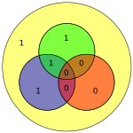
|
| 0100 | 1001100 | 
|
10011001 | 
|
| 1100 | 0111100 | 
|
01111000 | 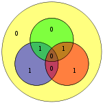
|
| 0010 | 0101010 | 
|
01010101 | 
|
| 1010 | 1011010 | 
|
10110100 | 
|
| 0110 | 1100110 | 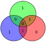
|
11001100 | 
|
| 1110 | 0010110 | 
|
00101101 | 
|
| 0001 | 1101001 | 
|
11010010 | 
|
| 1001 | 0011001 | 
|
00110011 | 
|
| 0101 | 0100101 | 
|
01001011 | 
|
| 1101 | 1010101 | 
|
10101010 | 
|
| 0011 | 1000011 | 
|
10000111 | 
|
| 1011 | 0110011 | 
|
01100110 | 
|
| 0111 | 0001111 | 
|
00011110 | 
|
| 1111 | 1111111 | 
|
11111111 | 
|


E7 lattice edit
The Hamming(7,4) code is closely related to the E7 lattice and, in fact, can be used to construct it, or more precisely, its dual lattice E7∗ (a similar construction for E7 uses the dual code [7,3,4]2). In particular, taking the set of all vectors x in Z7 with x congruent (modulo 2) to a codeword of Hamming(7,4), and rescaling by 1/√2, gives the lattice E7∗
![{\displaystyle E_{7}^{*}={\tfrac {1}{\sqrt {2}}}\left\{x\in \mathbb {Z} ^{7}:x{\bmod {2}}\in [7,4,3]_{2}\right\}.}](https://wikimedia.org/api/rest_v1/media/math/render/svg/3bb11cfc355357f26c8dc4477b46c6903b9c9aca)
This is a particular instance of a more general relation between lattices and codes. For instance, the extended (8,4)-Hamming code, which arises from the addition of a parity bit, is also related to the E8 lattice. [2]
References edit
- ^ "History of Hamming Codes". Archived from the original on 2007-10-25. Retrieved 2008-04-03.
- ^ Conway, John H.; Sloane, Neil J. A. (1998). Sphere Packings, Lattices and Groups (3rd ed.). New York: Springer-Verlag. ISBN 0-387-98585-9.
External links edit
- A programming problem about the Hamming Code(7,4)