


Summary
Inlet cones (sometimes called shock cones or inlet centerbodies[1]) are a component of some supersonic aircraft and missiles. They are primarily used on ramjets, such as the D-21 Tagboard and Lockheed X-7. Some turbojet aircraft including the Su-7, MiG-21, English Electric Lightning, and SR-71 also use an inlet cone.

Purpose edit
An inlet cone, as part of an Oswatitsch-type inlet used on a supersonic aircraft or missile, is the 3D-surface on which supersonic ram compression for a gas turbine engine or ramjet combustor takes place through oblique shock waves. Slowing the air to low supersonic speeds using a cone minimizes loss in total pressure (increases pressure recovery). Also, the cone, together with the inlet cowl lip, determine the area which regulates the flow entering the inlet. If the flow is more than that required by the engine then shock position instability(buzz) can occur. If less than that required then the pressure recovery is lower which reduces engine thrust.[2]
An inlet with cone may be used to supply high pressure air for ramjet equipment which would normally be shaft-driven on a turbine engine, eg to drive turbopumps for the fuel pump on the Bristol Thor ramjet and hydraulic power on the Bristol Bloodhound missile.
Shape edit
The cone angle is chosen such that, at the design condition for the inlet (Mach 1.7 for the English Electric Lightning inlet[3]), the shock wave that forms on its apex coincides with the cowl lip. The inlet passes its maximum airflow and achieves its maximum pressure recovery.[4] A higher design speed may require two oblique shocks focussed on the lip to maintain an acceptable pressure recovery and pass maximum airflow. In this case a biconic cone is required with two angles ( the Bristol Thor ramjet has 24 and 31 degrees for a design speed of Mach 2.5).[5] For higher speeds a more smoothly contoured transition between cone angles may be used in what is known as an isentropic spike (Marquardt RJ43 ramjet).[6]
The conical body may be a complete cone centerbody in a round inlet (MiG-21), a half cone in a side-fuselage inlet (Lockheed F-104 Starfighter) or a quarter cone in a side-fuselage/underwing inlet (General Dynamics F-111 Aardvark).
The rear of the cone beyond its maximum diameter, rear-facing and unseen inside the duct, is shaped for a similar reason to the protruding front part. The visible cone is a supersonic diffuser with a requirement for low loss in total pressure, and the rear, streamlined part, together with the internal surface profile of the duct, forms the subsonic diffuser, also with a requirement for low loss in total pressure as the air slows to the compressor entry Mach number.
For Mach numbers below about 2.2 all the shock compression is done externally. For higher Mach numbers part of the supersonic diffusion has to take place inside the duct, known as external/internal or mixed compression. In this case the rear part of the forward-facing conical surface, together with the internal surface profile of the duct, continues the supersonic diffusion with reflected oblique shocks until the final normal shock. In the case of the Lockheed SR-71 Blackbird with part of the supersonic compression taking place inside the ducting the spike and internal cowl surfaces were curved for gradual isentropic compression.[7] The inlet cone also has different axial positions to control how the capture area varies with the duct internal throat area. For best intake operation this required area ratio gets bigger with increasing flight Mach number, hence the large inlet cone movement on the SR-71 which had to perform well from low speeds to Mach 3.2. On the SR-71 the cone moves back at higher speeds.[8]
Operation edit
At subsonic flight speeds, the conical inlet operates much like a pitot intake or subsonic diffuser. However, as the vehicle goes supersonic a conical shock wave appears, emanating from the cone apex. The flow area through the shock wave decreases and the air is compressed. As the flight Mach number increases, the conical shock wave becomes more oblique and eventually impinges on the intake lip.
For higher flight speeds a moving cone becomes necessary to allow the supersonic compression to occur more efficiently over a wider range of speeds. With increasing flight speed, in typical Oswatitsch-type supersonic moving-cone inlet - the cone is moved forward (MiG-21), and if it is non-Oswatitsch-type cone inlet (SR-71) it is moved to the rear, or into the intake. In both cases, due to the shape of the cone surface and the internal duct surface the internal flow area gets less as required to continue compressing the air supersonically. The compression occurring in this path is called "internal compression" (as opposed to the "external compression" on the cone). At the minimum flow area, or throat, a normal or plane shock occurs. The flow area then increases for subsonic compression, or diffusion, up to the engine face.
The position of the cone within the intake is usually controlled automatically to keep the plane shock wave correctly located just downstream of the throat. Certain circumstances can cause the shock wave to be expelled from the intake. This is known as an unstart.
Alternative shapes edit
Some air inlets feature a biconic centrebody (MIG-21) to form two conic shock waves, both focused on the lip of the intake. This improves pressure recovery. Some aircraft (BAC TSR-2, F-104, Mirage III) use a semi-conic centrebody. The F-111 has a quarter cone, which moves axially, followed by an expanding cone section.
Concorde, Tu-144, F-15 Eagle, MiG-25 Foxbat, and the A-5 Vigilante use so-called 2D inlets, where the nacelle is rectangular and a flat intake ramp replaces the dual cones. Inlet ramps allow for swept inlet cowls (F-22 Raptor, F-35 Lightning II) to avoid shocks.
Some other supersonic aircraft (Eurofighter Typhoon) use a variable lower cowl lip[9] for high angle of attack operation and a bleed system (porous wall) incorporated on the intake ramp to facilitate stabilization of the shock system at supersonic Mach numbers. For the improvement of the intake flow (reduced distortion), air is dumped via an intake bleed slot on the ramp side downstream of the intake. The ramp, which is separated from the fuselage by a diverter, produces an oblique shock in order to decelerate the flow. The leading edge of the splitter plate separating the two intakes is located downstream of this oblique shock.[10]
Many supersonic aircraft (F-16 Fighting Falcon) dispense with the conical centrebody and employ a simple pitot intake. A detached, strong normal shock appears directly in front of the inlet at supersonic flight speeds, which leads to poor pressure recovery.
NASA has tested an alternative to the external/internal, or mixed compression inlet, needed for speeds above about Mach 2.2 (below that speed inlets with all-external compression are used). The mixed-compression inlet is susceptible to unstarts or expulsion of the internal shock to in front of the inlet. The NASA inlet, which they call a Parametric Inlet, does all the supersonic compression externally so there is no shock inside the ducting in a potentially unstable location.[1]
Different types of inlet cone edit
-
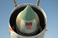
 Lightning fixed cone
 -
 F-111C fixed quarter-cone
 -
 Su-22 translating cone
 -
 Mirage III translating half-cone
 -
 SR-71 translating cone positions
 -
 Marquardt RJ43 ramjets with isentropic spike attached to Bomarc missiles
 -
-
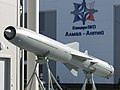
 P-500 Bazalt anti-ship missile


See also edit
References edit
- ^ NASA Dryden[permanent dead link] Centerbody inlet for F-15
- ^ "Aircraft Propulsion", P.J.McMahon 1971, ISBN 0 273 42324 X, p.216,262
- ^ "Testing Years', Roland Beamont 1980, ISBN 0 7110 1072 2, p.105
- ^ "Jet Propulsion For Aerospace Applications" Second Edition, Hesse and Mumford 1964, Library of Congress Catalog Card Number: 64-18757, section 5.7 "Modes of Supersonic Diffuser Operation"
- ^ "Ramjet Intakes", T.Cain, Gas Dynamics Ltd.,2 Clockhouse Road, Farnborough, GU147QY, Hampshire, UK, RTO-EN-AVT-185, p.5-10
- ^ "Jet Propulsion For Aerospace Applications" Second Edition, Hesse and Mumford 1964, Library of Congress Catalog Card Number:64-18757, p.383
- ^ "Supersonic Inlet For Jet Engines' David H.Campbell, Lockheed Aircraft Corporation, United States Patent Office 3,477,455
- ^ "Supersonic Inlet For Jet Engines", David H.Campbell, Lockheed Aircraft Corporation, United States Patent Office, 3,477,455
- ^ http://data3.primeportal.net/hangar/luc_colin3/eurofighter_typhoon_ehlw/images/eurofighter_typhoon_ehlw_58_of_59.jpg [bare URL image file]
- ^ ADPO11111 TITLE: Thrust Vectoring for Advanced Fighter Aircraft - High Angle of Attack Intake Investigations
- Grundlagen der Gasdynamik; Klaus OSWATITSCH. Springer, 1976.
- Benson, T. (2004). High Speed Aerodynamics Index. Retrieved Nov. 19, 2004.
- Eden, P. & Moeng, S. (2002). Modern Military Aircraft Anatomy. Aerospace Publishing Ltd. ISBN 1-58663-684-7.
External links edit
![]() Media related to Inlet cones at Wikimedia Commons
Media related to Inlet cones at Wikimedia Commons