


Summary
A log amplifier, also known as logarithmic amplifier or logarithm amplifier or log amp, is an amplifier for which the output voltage Vout is K times the natural log of the input voltage Vin. This can be expressed as,

where Vref is the normalization constant in volts and K is the scale factor.
The log amplifier gives an output voltage which is proportional to the logarithm of the applied input voltage. To design a log amplifier circuit, high performance op-amps like LM1458, LM771, LM714 are commonly used and a compensated log amplifier may include more than one. In some situations, especially in RF domain, monolithic log amplifiers are also used to reduce number of components and space used, as well improve bandwidth and noise performance.
The log amplifier's operation can be inverted by an exponentiator, such as an op-amp configured for exponential output.[1]
Log amplifier applications edit
Log amplifiers are used in many ways, such as:
- To perform mathematical operations like multiplication, division and exponentiation. Multiplication is also sometimes called mixing. This is similar to operation of a slide rule, and is used in analog computers, audio synthesis methods, and some measurement instruments (i.e. power as multiplication of current and voltage).
- To calculate the dB value of a given quantity.
- As a True RMS converter.
- Extending dynamic range of other circuits, like automatic gain control of transmit power in RF circuits, or analog-to-digital converters.
Drawbacks of basic log amplifier configuration edit
The reverse saturation current for the diode doubles for every ten degree Celsius rise in temperature. Similarly the emitter saturation current varies significantly from one transistor to another and also with temperature. Hence, it is very difficult to set the reference voltage for the circuit.[2]
Basic op-amp diode circuit edit
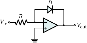
The relationship between the input voltage and the output voltage is given by:


where and are the saturation current and the thermal voltage of the diode respectively.


The dynamic range of this basic op-amp diode circuit is limited to 40-60 dB because of non-ideal diode characteristics, but the dynamic range can be increased to over 120 dB by replacing the diode with a transistor in a "transdiode" configuration.[3]
Transdiode configuration edit

A necessary condition for successful operation of a log amplifier is that the input voltage, Vin, is always positive. This may be ensured by using a rectifier and filter to condition the input signal before applying it to the log amplifier's input. As Vin is positive, Vout is obliged to be negative (since the op amp is in the inverting configuration) and is large enough to forward bias the emitter-base junction of the BJT keeping it in the active mode of operation. Now,

where is the saturation current of the emitter-base diode and is the thermal voltage. Due to the virtual ground at the op amp differential input,


- , and


The output voltage is expressed as the natural log of the input voltage. Both the saturation current and the thermal voltage are temperature dependent, hence, temperature compensating circuits may be required.
See also edit
References edit
- ^ https://www.ti.com/lit/an/snoa575b/snoa575b.pdf [bare URL PDF]
- ^ RMS-to-DC Conversion Just Got Easy Linear Technology, Design Note 288, 2002
- ^ "MT-077 Tutorial: Log Amp Basics" (PDF). Analog Devices. 2009. Archived (PDF) from the original on 2022-10-29. Retrieved 2023-06-28.
External links edit
- Integrated DC logarithmic amplifiers from Maxim's AN 36211
- Analog electronics with Op Amps by A. J. Peyton, V. Walsh