


Summary
A simple machine that exhibits mechanical advantage is called a mechanical advantage device - e.g.:
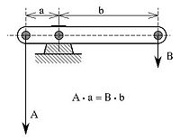
- Lever: The beam shown is in static equilibrium around the fulcrum. This is due to the moment created by vector force "A" counterclockwise (moment A*a) being in equilibrium with the moment created by vector force "B" clockwise (moment B*b). The relatively low vector force "B" is translated in a relatively high vector force "A". The force is thus increased in the ratio of the forces A : B, which is equal to the ratio of the distances to the fulcrum b : a. This ratio is called the mechanical advantage. This idealised situation does not take into account friction.
- Wheel and axle motion (e.g. screwdrivers, doorknobs): A wheel is essentially a lever with one arm the distance between the axle and the outer point of the wheel, and the other the radius of the axle. Typically this is a fairly large difference, leading to a proportionately large mechanical advantage. This allows even simple wheels with wooden axles running in wooden blocks to still turn freely, because their friction is overwhelmed by the rotational force of the wheel multiplied by the mechanical advantage.
- A block and tackle of multiple pulleys creates mechanical advantage, by having the flexible material looped over several pulleys in turn. Adding more loops and pulleys increases the mechanical advantage.
- Screw: A screw is essentially an inclined plane wrapped around a cylinder. The run over the rise of this inclined plane is the mechanical advantage of a screw.[1]
Pulleys edit
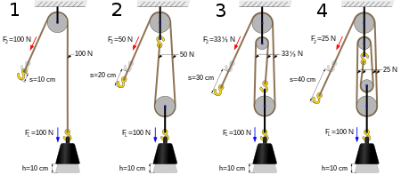
Consider lifting a weight with rope and pulleys. A rope looped through a pulley attached to a fixed spot, e.g. a barn roof rafter, and attached to the weight is called a single pulley. It has a mechanical advantage (MA) = 1 (assuming frictionless bearings in the pulley), moving no mechanical advantage (or disadvantage) however advantageous the change in direction may be.
A single movable pulley has an MA of 2 (assuming frictionless bearings in the pulley). Consider a pulley attached to a weight being lifted. A rope passes around it, with one end attached to a fixed point above, e.g. a barn roof rafter, and a pulling force is applied upward to the other end with the two lengths parallel. In this situation the distance the lifter must pull the rope becomes twice the distance the weight travels, allowing the force applied to be halved. Note: if an additional pulley is used to change the direction of the rope, e.g. the person doing the work wants to stand on the ground instead of on a rafter, the mechanical advantage is not increased.
By looping more ropes around more pulleys we can construct a block and tackle to continue to increase the mechanical advantage. For example, if we have two pulleys attached to the rafter, two pulleys attached to the weight, one end attached to the rafter, and someone standing on the rafter pulling the rope, we have a mechanical advantage of four. Again note: if we add another pulley so that someone may stand on the ground and pull down, we still have a mechanical advantage of four.
Here are examples where the fixed point is not obvious:
- A velcro strap on a shoe passes through a slot and folds over on itself. The slot is a movable pulley and the MA = 2.
- Two ropes laid down a ramp attached to a raised platform. A barrel is rolled onto the ropes and the ropes are passed over the barrel and handed to two workers at the top of the ramp. The workers pull the ropes together to get the barrel to the top. The barrel is a movable pulley and the MA = 2. If there is enough friction where the rope is pinched between the barrel and the ramp, the pinch point becomes the attachment point. This is considered a fixed attachment point because the rope above the barrel does not move relative to the ramp. Alternatively the ends of the rope can be attached to the platform.
Screws edit
The theoretical mechanical advantage for a screw can be calculated using the following equation:[2]

where
- dm = the mean diameter of the screw thread
- l = the lead of the screw thread
Note that the actual mechanical advantage of a screw system is greater, as a screwdriver or other screw driving system has a mechanical advantage as well.
- Inclined plane: MA = length of slope ÷ height of the slope
See also edit
References edit
Notes edit
Bibliography edit
External links edit
- Gears and pulleys
- Mechanical engineering — pulleys
- Mechanical advantage — video