


Summary
Melt spinning is a metal forming technique that is typically used to form thin ribbons of metal or alloys with a particular atomic structure.[1]

Some important commercial applications of melt-spun metals include high-efficiency transformers (Amorphous metal transformer), sensory devices, telecommunications equipment, and power electronics.[2]
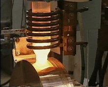
A typical melt spinning process involves casting molten metal by jetting it onto a rotating wheel or drum, which is cooled internally, usually by water or liquid nitrogen. The molten material rapidly solidifies upon contact with the large, cold surface area of the drum. The rotation of the drum constantly removes the solidified product while exposing new surface area to the molten metal stream, allowing for continuous production. The resulting ribbon is then directed along the production line to be packaged or machined into further products.[3][4]
The cooling rates achievable by melt spinning are on the order of 104–106 Kelvins per second (K/s). Consequently, melt spinning is used to develop materials that require extremely high cooling rates in order to form, such as metallic glasses. Due to their rapid cooling, these products have a highly disordered atomic structure which gives them unique magnetic and physical properties (see amorphous metals).[3][5][6]
Several variations to the melt spinning process provide specific advantages. These processes include planar flow casting, twin roll melt spinning, and auto ejection melt spinning.
Originating with Robert Pond in a series of related patents from 1958 to 1961 (US Patent Nos. 2825108, 2910744, and 2976590), the current concept of the melt spinner was outlined by Pond and Maddin in 1969. At first, the liquid was quenched on the inner surface of a drum. Liebermann and Graham further developed the process as a continuous casting technique by 1976, this time on the drum's outer surface.[7] The process can continuously produce thin ribbons of material, with sheets several inches in width commercially available.[8]
Process edit
In melt spinning, the alloy or metal is first melted in a crucible. Then, an inert gas, usually argon, is used to jet the molten material out of a nozzle located on the underside of the crucible. The resulting stream of liquid is directed onto the outer circumferential surface of a rotating wheel or drum which is cooled internally. The drum's outer surface is located extremely close to the nozzle but does not touch it. Generally, the velocity of the drum's surface must be between 10 m/s and 60 m/s in order to avoid the formation of globules (droplets) or breaking the ribbon respectively. Once the stream contacts the drum's surface, a small puddle of melt (molten material) is formed. Due to the low viscosity of the melt, the shear forces generated by the relative movement of the drum's surface underneath the melt only extend a few microns into the puddle. In other words, only a small amount of the puddle is affected by the friction from the rotation of the drum. Consequently, as the drum spins, most of the melt puddle remains held between the nozzle and the drum by surface tension. However, the melt on the very bottom of the puddle, which is in direct contact with the drum, rapidly solidifies into a thin ribbon. The solidified ribbon is carried away from under the nozzle on the drum's surface for up to 10° of rotation before centrifugal force from the drum's rotation ejects it.[1][4][9]
This process occurs continuously, so as solidified material is removed from underneath the puddle of melt, more liquid material is added to the puddle from the nozzle.
Varying factors edit
There are many factors at play in even a basic melt spinning process. The quality and dimensions of the product are determined by how the machine is operated and configured. Consequently, there are many studies exploring the effects of variations in the melt spinner's configuration on specific alloys. For example, here is an article about the specific conditions that were found to work well for melt spinning Fe-B and Fe-Si-B alloys.
In general, melt spinners will run with some variation in the following variables depending on the desired product.
- Nozzle gap: The distance between the nozzle and the cooled drum. Primarily affects ribbon thickness.
- Nozzle shape: The shape of the nozzle ejecting the molten material onto the drum. Nozzles allowing for a larger melt puddle on the drum's surface result in wider ribbons.
- Flow rate: The flow rate of melt onto the drum. The flow rate is usually closely related to the rotational speed of the drum. Mainly affects the width and thickness of the ribbons.
- Rotational speed: The speed at which the drum rotates. In general, a faster drum makes thinner ribbons.
- Drum temperature: The temperature at which the drum operates. Mainly affects the atomic structure of the resulting ribbon. Different alloys form best at specific temperatures.
Since every material acts differently, the exact cause-effect relationship between each of these variables and the resulting ribbon is usually determined experimentally. Other less commonly adjusted variables exist, but their effects on the final ribbon dimensions and structure aren't all documented.[1][10][11]
Modifications edit
Different processes and techniques have been developed around melt spinning which offer advantages to the industrial applications and product consistency.
Planar Flow Casting edit
Planar Flow Casting (PFC) is a commonly used melt spinning process for the industrial fabrication of wide metallic glass sheets. In this process, the primary modification is that a much wider nozzle is used to eject the melt from the crucible. As a result, the melt puddle covers a larger area of the drum, which in turn forms a larger area of ribbon.[9] PFC is commonly cast in a vacuum to avoid oxidation of the molten material, which would affect the quality of the resulting product. Ribbons up to 200 mm wide have been industrially achieved using PFC.[12]
Twin Roll Melt Spinning edit
In Twin Roll Melt Spinning two rollers or drums are used instead of one. The rollers are placed side by side, and rotated such that the one to the left spins clockwise, and the one on the right spins counter-clockwise. This configuration results in material passing between the rollers being pulled down. The melt is jetted between the rollers where it is cooled and ejected as a ribbon. The advantage of twin-roll melt spinning is that it gives a high degree of control over the thickness of the resulting ribbon. With a single roller, controlling ribbon thickness is complicated involving close control over the flow rate of the melt, rotational speed of the wheel, and temperature of the melt. With the twin roller setup, a particular and consistent thickness can be achieved by simply changing the distance between the rollers.
To date, twin roll melt spinning is still limited almost exclusively to laboratory scales.[13][14]
Auto Ejection Melt Spinning edit
Auto Ejection Melt Spinning (AEMS) describes a type of melt spinning where ejection of the melt occurs as soon as it has liquefied, eliminating the need for a technician to manually control the flow rate, temperature, and/or release timing of the melt stream.[1]
This modification allows for a much higher ribbon consistency between runs, and a greater level of automation in the process.
Product edit
Melt spinning is used to manufacture thin metal sheets or ribbons that are near amorphous or non-crystalline. The unique resulting electric and magnetic properties of melt-spun metals are a consequence of this structure as well as the composition of the alloy or metal that was used to form the ribbon.
Structure edit
Normally, when a metallic material cools, the individual atoms solidify in strong, repeating patterns to form a crystalline solid. However, in melt spinning, the melt is quenched (cooled) so rapidly that the atoms don't have time to form these ordered structures before they completely solidify. Instead, the atoms are solidified in positions resembling their liquid state. This physical structure gives rise to the magnetic and electric properties of amorphous metals.[6]
Electric and Magnetic Properties edit
The amorphous material produced by melt spinning is considered a soft magnet. That is to say that their natural coercivity is less than 1000 Am-1, which means that the metal's magnetism is more responsive to outside influences and as a result can be easily switched on and off. This makes amorphous metals particularly useful in applications requiring the repeated magnetization and demagnetization of a material in order to function. Certain amorphous alloys also provide the ability to enhance and or channel flux created by electrical currents, making them useful for magnetic shielding and insulation.
The exact magnetic properties of each alloy depend mostly on the atomic composition of the material. For example, nickel-iron alloys with a lower amount of nickel have a high electrical resistance, while those with a higher percentage of nickel have a high magnetic permeability.[15][2]
See also edit
References edit
- ^ a b c d Shirzadi, A. A.; Kozieł, T.; Cios, G.; Bała, P. (2019-02-01). "Development of Auto Ejection Melt Spinning (AEMS) and its application in fabrication of cobalt-based ribbons". Journal of Materials Processing Technology. 264: 377–381. doi:10.1016/j.jmatprotec.2018.09.028. ISSN 0924-0136.
- ^ a b Hasegawa, Ryusuke (2000-06-02). "Present status of amorphous soft magnetic alloys". Journal of Magnetism and Magnetic Materials. 215–216 (1): 240–245. Bibcode:2000JMMM..215..240H. doi:10.1016/S0304-8853(00)00126-8. ISSN 0304-8853.
- ^ a b Cahn, Robert W.; Haasen, Peter (2014), "Preface to the Third Edition", Physical Metallurgy, Elsevier, pp. xv–xvi, doi:10.1016/b978-0-444-53770-6.05002-4, ISBN 9780444537706
- ^ a b Budhani, R. C.; Goel, T. C.; Chopra, K. L. (1982-12-01). "Melt-spinning technique for preparation of metallic glasses". Bulletin of Materials Science. 4 (5): 549–561. doi:10.1007/BF02824962. ISSN 0973-7669.
- ^ Voo, N. Y.; Olofinjana, A. O. (2017-01-01). "Multi-stream Casting of Wire Directly from Melt". Procedia Engineering. 13th Global Congress on Manufacturing and Management Zhengzhou, China 28–30 November 2016. 174: 195–205. doi:10.1016/j.proeng.2017.01.204. ISSN 1877-7058.
- ^ a b Fedsteel (2016-04-20). "What is an Amorphous Metal?". FedSteel.com. Retrieved 2019-10-16.
- ^ Liebermann, H.; Graham, C. (November 1976). "Production of amorphous alloy ribbons and effects of apparatus parameters on ribbon dimensions". IEEE Transactions on Magnetics. 12 (6): 921–923. Bibcode:1976ITM....12..921L. doi:10.1109/TMAG.1976.1059201.
- ^ Egami, T. (December 1984). "Magnetic amorphous alloys: physics and technological applications". Reports on Progress in Physics. 47 (12): 1601–1725. doi:10.1088/0034-4885/47/12/002. S2CID 250756792.
- ^ a b Carpenter, J. K.; Steen, P. H. (1992-01-01). "Planar-flow spin-casting of molten metals: process behaviour". Journal of Materials Science. 27 (1): 215–225. doi:10.1007/BF00553859. ISSN 1573-4803. S2CID 137640227.
- ^ Steen, Paul H.; Karcher, Christian (1997). "Fluid Mechanics of Spin Casting of Metals". Annual Review of Fluid Mechanics. 29 (1): 373–397. Bibcode:1997AnRFM..29..373S. doi:10.1146/annurev.fluid.29.1.373.
- ^ Pavuna, Davor (1981-09-01). "Production of metallic glass ribbons by the chill-block melt-spinning technique in stabilized laboratory conditions". Journal of Materials Science. 16 (9): 2419–2433. Bibcode:1981JMatS..16.2419P. doi:10.1007/BF01113578. ISSN 1573-4803. S2CID 135709527.
- ^ Seino, Ryu; Sato, Yuichi (2014-02-15). "Observation of melt puddle behavior in planar flow casting in air". Journal of Alloys and Compounds. SI : ISMANAM 2012. 586: S150–S152. doi:10.1016/j.jallcom.2013.04.189. ISSN 0925-8388.
- ^ Wright, R. N.; Korth, G. E.; Sellers, C. H. (1998-09-09), "A containerless‐melting twin‐roller melt‐spinning system", Review of Scientific Instruments (letter), 61 (12): 3924–3926, doi:10.1063/1.1141529
- ^ Pei, Zhipu; Ju, Dongying (2017-04-17). "Simulation of the Continuous Casting and Cooling Behavior of Metallic Glasses". Materials. 10 (4): 420. Bibcode:2017Mate...10..420P. doi:10.3390/ma10040420. ISSN 1996-1944. PMC 5506926. PMID 28772779.
- ^ "Magnetic Materials: Soft Magnets" (PDF). Birmingham University.
External links edit
- YouTube video of melt spinning process.
- An example of a melt spinner http://www.arcastinc.com/meltspin.htm .