


Summary
The Northrop X-21A was an experimental aircraft designed to test wings with laminar flow control. It was based on the Douglas WB-66D airframe, with the wing-mounted engines moved to the rear fuselage and making space for air compressors. The aircraft first flew on 18 April 1963 with NASA test pilot Jack Wells at the controls.[1] Although useful testing was accomplished, the extensive maintenance of the intricate laminar-flow system caused the end of the program.
| X-21 | |
|---|---|
| |
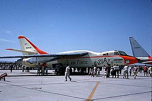
| Northrop X-21A | |
| Role | Experimental aircraft |
| Manufacturer | Northrop |
| First flight | 18 April 1963 |
| Introduction | Experimental |
| Retired | 1968 |
| Primary user | National Aeronautics and Space Administration (NASA) |
| Number built | 2 |
| Developed from | Douglas B-66 Destroyer |
Design and development edit
Laminar-flow control is a technology that offers the potential for significant improvement in drag coefficient which would provide improvements in aircraft fuel usage, range or endurance that far exceed any known single aeronautical technology. In principle, if 80% of wing is laminar, then overall drag could be reduced by 25%. The frictional force between the air and the aircraft surface, known as viscous drag, is much larger in a turbulent boundary layer than in a laminar one. The principal type of active laminar-flow control is removal of a small amount of the boundary-layer air by suction through porous materials, multiple narrow surface slots, or small perforations (boundary layer suction).
Two major modifications were required, the first involving the standard underwing podded Allison J71 engines being removed and replaced by a pair of 9,490 lbf (42 kN) static thrust General Electric XJ79-GE-13 non-afterburning turbojets mounted in pods attached to the rear of the fuselage sides. Bleed air from the J79 engines was fed into a pair of underwing fairings, each of which housed a "bleed-burn" turbine which sucked the boundary layer air out through the wing slots.
The X-21A test vehicles (55-0408 and 55-0410) also incorporated sophisticated laminar flow control systems built into a completely new wing of increased span and area, with a sweep reduced from 35° to 30°. The wing had a multiple series of span-wise slots (800,000 in total)[2] through which turbulent boundary-layer was "sucked in," resulting in a smoother laminar flow. Theoretically, reduced drag, better fuel economy and longer range could be achieved.[3]
The forward cockpit carried a pilot and two flight engineers while two additional flight test engineers were housed in a central fuselage bay underneath the wing.
Testing edit

In initial testing there were significant problems with the porous materials and surface slots getting plugged with debris, bugs, and even rain. In certain conditions, ice crystals would form due to the rapid cooling of air over the laminar surfaces. This would abruptly disrupt laminar flow, causing rapid melting and rapid transition back to turbulent flow. Maximum achievement of 95% laminar flow over those areas was desired.[2] However, the design effort was canceled due to the plugging problems.
Pioneering data were obtained in the X-21 flight program, including the effects of surface irregularities, boundary-layer turbulence induced by three-dimensional span-wise flow effects in the boundary layer (referred to as span-wise contamination) and degrading environmental effects such as ice crystals in the atmosphere.[4]
Disposition edit
Both X-21As ended up in storage at Edwards Air Force Base, California, where they gradually became derelicts, used primarily as photo targets. The remains can still be viewed, but no efforts have been made to recover either example for restoration or display.[2][5]
Specifications (X-21A) edit

General characteristics
- Crew: Five
- Length: 75 ft 3 in (22.94 m)
- Wingspan: 93 ft 6 in (28.51 m)
- Height: 25 ft 7 in (7.8 m)
- Wing area: 1,250 sq ft (116.17 m2)
- Empty weight: 45,828 lb (20,783 kg)
- Gross weight: 83,000 lb (37,727 kg)
- Powerplant: 2 × General Electric J79-GE-13 turbojets, 9,400 lbf (42 kN) thrust each
Performance
- Maximum speed: 487 kn (560 mph, 896 km/h)
- Range: 4,156 nmi (4,780 mi, 7,697 km)
- Service ceiling: 42,500 ft (12,957 m)
See also edit
Related development
References edit
- Notes
- ^ American X-Vehicles: An Inventory, June 2003. Retrieved: 13 February 2007.
- ^ a b c Winchester 2005 p. 297.
- ^ Baugher, Joe. Northrop X-21A Retrieved: 14 February 2007.
- ^ Chambers, Joseph R. Laminar-flow Control: The Holy Grail of Aerodynamics NASA, p. 133–134.
- ^ Jenkins, Dennis R. X-Planes Photo Scrapbook. North Branch, Minnesota: Specialty Press, 2004. ISBN 1-58007-076-0
- Bibliography
- Winchester, Jim. X-Planes and Prototypes. London: Amber Books Ltd., 2005. ISBN 1-904687-40-7.
- "X-Planes Detailed Data – Northrop X-21A" Retrieved: 15 November 2017.
External links edit
- Globasecurity.org – X-21 Laminar Flow Control
- aeroweb.brooklyn.cuny.edu – Northrop X-21A
- Plattner, C. M. X-21 Tests Laminar Flow Control Theory. // Aviation Week & Space Technology, June 24, 1963, v. 78, no. 25, pp. 52–62.