


Summary
An oil burner is a heating device which burns #1, #2 and #6 heating oils, diesel fuel or other similar fuels. In the United States, ultra low sulfur #2 diesel is the common fuel used. It is dyed red to show that it is road-tax exempt. In most markets of the United States, heating oil is the same specification of fuel as on-road un-dyed diesel.
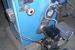
An oil burner is a part attached to an oil furnace, water heater, or boiler.[1] It provides the ignition of heating oil/biodiesel fuel used to heat either air or water via a heat exchanger. The fuel is atomized into a fine spray usually by forcing it under pressure through a nozzle which gives the resulting flame a specific flow rate, angle of spray and pattern (variations of a cone shape). This spray is usually ignited by an electric spark with the air being forced through around it at the end of a blast tube, by a fan driven by the oil burner motor.[2] The fuel pump is typically driven via a coupling connecting its shaft to the motor.
In the United States residential home heating oil market the "vaporizing gun burner" is the most common mechanical device used to heat a home or small commercial forced air space with.[3] These simple burners may achieve a lifespan of several decades with regular maintenance.
The maintenance in a gun burner usually involves a replacement of the nozzle used to atomize the fuel, replacing the filter located at the air handler, replacing the fuel filter on the heating oil system from the tank, cleaning out any soot or deposits in the heat exchanger of the furnace, and ensuring the system is in good working order. It also involves checking and adjusting the fuel-air mixture for efficiency with a combustion analyzer.
If a heating oil burner runs out of oil, it often must be primed to be restarted. Priming involves purging any air from the fuel lines so that a steady flow of oil can find its way to the burner.
If an oil burner wears out, it can usually be upgraded and replaced with a more efficient modern burner. If the heat exchanger wears out, a new furnace is required. Oil furnaces can last decades if maintained regularly ensuring the heat exchanger is vacuumed out and cleaned. Oil burners deposit soot in the heat exchanger, which insulates unevenly and causes temperature gradients and uneven stresses throughout the steel, potentially leading to cracking. Annual or every other year tune-ups guarantee this wear is far reduced. Oil furnace lifespans of 50-75 years with regular service are not uncommon, compared to the approximately 20-year lifespan of natural gas furnaces.
Fuel injection edit
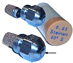
Fuel is injected into the combustion chamber at high pressure by a spray nozzle. Fuel nozzles are usually rated in fuel volume flow per unit time e.g. US gallons per hour.
A fuel nozzle is characterized by three features:
- Flow at 100 psi pump pressure (e.g. 0.65 gallons per hour)
- Spray characteristic (e.g. "B" indicating a solid cone-shaped spray)[4]
- Spray angle (e.g. 60°, indicating the width of the cone)
Because of erosion from friction with the oil, and possible blockage due to debris in the fuel, they need replacement when worn.
Alternatively to standard nozzles, fuel may be passed in front of a tiny orifice fed with compressed air. This arrangement is referred to as a Babington atomiser or Babington nozzle, named after its inventor Robert Babington.[5] As the oil flows in front of the nozzle and not through it, high fuel pressure is not needed. Because it is only compressed air that passes through the orifice hole, such nozzles do not suffer from significant erosion.
Oil pump edit

Oil pressure is generated by an electric pump, usually driven by a capacitor start motor. The pump consists of two parts:
Gear pump assembly edit
A gear pump pumps the oil in and increases the pressure to a maximum 15 bar (217.5 psi) before it is fed to the nozzles. Usually, a gerotor of the sickle type is used. Gear pumps are used frequently in oil burners because of their simplicity, durability, and low price.
Pressure regulator edit
To set the heat output of the burner, the rate of fuel delivery via the nozzle must be adjustable. This is often achieved by an adjustable pressure relief valve between the pump and the nozzle. When the set pressure is reached (usually 100 psi), this valve opens and allows excess oil to flow through a bypass back to the fuel tank or the pump suction side.
Electromagnetic valve edit

This allows fuel to be shut off from the sprayer by electrical control. It helps avoid drips when the valve is closed. It also eases the purging of the burner (and any boiler) of fuel mist during startup, or while restarting after a misfire. If the burner were not purged the oil/air mixture could explode.
Fan edit
The fan blows air into the combustion chamber. The rotor of the fan is powered by an electric motor.
Igniters edit
Some oil burners use glow bars which operate much like the glow plugs of a diesel engine.
Many use high voltage to create a spark for ignition, somewhat similar to a spark plug. In the past, transformers were used to generate the high voltage. In the mid-90s, electronic igniters were introduced, solving many problems related to the old style transformer. This new technology in igniters would soon replace all old style transformers throughout the oil burner industry. Electronic igniters run cooler, so the output voltage could be increased from 10,000 to 20,000 VAC, resulting in faster, more reliable ignition. A standard igniter draws around 35 milliamps.
Safety control edit

Oil-fired burners are fitted with a safety mechanism to confirm proper ignition. The terms "primary control", "safety control", "cad cell control", "master control", and "fire-eye control" are variously used to describe a light dependent resistor (LDR) which detects the flame whose value changes by the amount of light it is exposed to. The resistance decreases as the LDR is exposed to more light. The material is usually cadmium sulfide, hence the name "cad cell" for this component. In darkness the resistance is around 1 MΩ, while when exposed to light from a properly ignited flame the resistance is much lower, around 75–300 Ω.
Older oil burners were equipped with a primary control installed on the exhaust stack with a bimetallic heat sensing element protruding into the stack, such a control was referred to as a "stack relay" or a "stack control". It performed the same function as the newer cad-cell control, but instead of sensing light from the burner flame, it sensed the heat of exhaust gases to confirm ignition.
See also edit
References edit
- ^ "Thermopride Oil Furnaces". thermopride.com. March 28, 2018. Retrieved March 28, 2018.
- ^ James L. Kittle (1990). Home Heating & Air Conditioning Systems. McGraw-Hill Professional. ISBN 0-8306-3257-3.
- ^ "Beckett Burner Corp". beckettcorp.com/. March 28, 2018.
- ^ "Oil Burner Nozzle Series" (PDF). Sid Harvey Industries. December 22, 2023. Archived (PDF) from the original on December 22, 2023. Retrieved December 22, 2023.
- ^ "Robert S. BABINGTON Nebulizer Fuel Burner". 1976.