


Summary
An optical telescope is a telescope that gathers and focuses light mainly from the visible part of the electromagnetic spectrum, to create a magnified image for direct visual inspection, to make a photograph, or to collect data through electronic image sensors.

There are three primary types of optical telescope:
- Refracting telescopes, which use lenses and less commonly also prisms (dioptrics)
- Reflecting telescopes, which use mirrors (catoptrics)
- Catadioptric telescopes, which combine lenses and mirrors
An optical telescope's ability to resolve small details is directly related to the diameter (or aperture) of its objective (the primary lens or mirror that collects and focuses the light), and its light-gathering power is related to the area of the objective. The larger the objective, the more light the telescope collects and the finer detail it resolves.
People use optical telescopes (including monoculars and binoculars) for outdoor activities such as observational astronomy, ornithology, pilotage, hunting and reconnaissance, as well as indoor/semi-outdoor activities such as watching performance arts and spectator sports.
History edit
The telescope is more a discovery of optical craftsmen than an invention of a scientist.[1][2] The lens and the properties of refracting and reflecting light had been known since antiquity, and theory on how they worked was developed by ancient Greek philosophers, preserved and expanded on in the medieval Islamic world, and had reached a significantly advanced state by the time of the telescope's invention in early modern Europe.[3][4] But the most significant step cited in the invention of the telescope was the development of lens manufacture for spectacles,[2][5][6] first in Venice and Florence in the thirteenth century,[7] and later in the spectacle making centers in both the Netherlands and Germany.[8] It is in the Netherlands in 1608 where the first documents describing a refracting optical telescope surfaced in the form of a patent filed by spectacle maker Hans Lippershey, followed a few weeks later by claims by Jacob Metius, and a third unknown applicant, that they also knew of this "art".[9]
Word of the invention spread fast and Galileo Galilei, on hearing of the device, was making his own improved designs within a year and was the first to publish astronomical results using a telescope.[10] Galileo's telescope used a convex objective lens and a concave eye lens, a design is now called a Galilean telescope. Johannes Kepler proposed an improvement on the design[11] that used a convex eyepiece, often called the Keplerian Telescope.
The next big step in the development of refractors was the advent of the Achromatic lens in the early 18th century,[12] which corrected the chromatic aberration in Keplerian telescopes up to that time—allowing for much shorter instruments with much larger objectives.[citation needed]
For reflecting telescopes, which use a curved mirror in place of the objective lens, theory preceded practice. The theoretical basis for curved mirrors behaving similar to lenses was probably established by Alhazen, whose theories had been widely disseminated in Latin translations of his work.[13] Soon after the invention of the refracting telescope, Galileo, Giovanni Francesco Sagredo, and others, spurred on by their knowledge that curved mirrors had similar properties to lenses, discussed the idea of building a telescope using a mirror as the image forming objective.[14] The potential advantages of using parabolic mirrors (primarily a reduction of spherical aberration with elimination of chromatic aberration) led to several proposed designs for reflecting telescopes,[15] the most notable of which was published in 1663 by James Gregory and came to be called the Gregorian telescope,[16][17] but no working models were built. Isaac Newton has been generally credited with constructing the first practical reflecting telescopes, the Newtonian telescope, in 1668[18] although due to their difficulty of construction and the poor performance of the speculum metal mirrors used it took over 100 years for reflectors to become popular. Many of the advances in reflecting telescopes included the perfection of parabolic mirror fabrication in the 18th century,[19] silver coated glass mirrors in the 19th century, long-lasting aluminum coatings in the 20th century,[20] segmented mirrors to allow larger diameters, and active optics to compensate for gravitational deformation. A mid-20th century innovation was catadioptric telescopes such as the Schmidt camera, which uses both a lens (corrector plate) and mirror as primary optical elements, mainly used for wide field imaging without spherical aberration.[citation needed]
The late 20th century has seen the development of adaptive optics and space telescopes to overcome the problems of astronomical seeing.[citation needed]
The electronics revolution of the early 21st century led to the development of computer-connected telescopes in the 2010s that allow non-professional skywatchers to observe stars and satellites using relatively low-cost equipment by taking advantage of digital astrophotographic techniques developed by professional astronomers over previous decades. An electronic connection to a computer (smartphone, pad, or laptop) is required to make astronomical observations from the telescopes. The digital technology allows multiple images to be stacked while subtracting the noise component of the observation producing images of Messier objects and faint stars as dim as an apparent magnitude of 15 with consumer-grade equipment.[21][22]
Principles edit
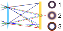
The basic scheme is that the primary light-gathering element, the objective (1) (the convex lens or concave mirror used to gather the incoming light), focuses that light from the distant object (4) to a focal plane where it forms a real image (5). This image may be recorded or viewed through an eyepiece (2), which acts like a magnifying glass. The eye (3) then sees an inverted, magnified virtual image (6) of the object.

Inverted images edit
Most telescope designs produce an inverted image at the focal plane; these are referred to as inverting telescopes. In fact, the image is both turned upside down and reversed left to right, so that altogether it is rotated by 180 degrees from the object orientation. In astronomical telescopes the rotated view is normally not corrected, since it does not affect how the telescope is used. However, a mirror diagonal is often used to place the eyepiece in a more convenient viewing location, and in that case the image is erect, but still reversed left to right. In terrestrial telescopes such as spotting scopes, monoculars and binoculars, prisms (e.g., Porro prisms) or a relay lens between objective and eyepiece are used to correct the image orientation. There are telescope designs that do not present an inverted image such as the Galilean refractor and the Gregorian reflector. These are referred to as erecting telescopes.
Design variants edit
Many types of telescope fold or divert the optical path with secondary or tertiary mirrors. These may be integral part of the optical design (Newtonian telescope, Cassegrain reflector or similar types), or may simply be used to place the eyepiece or detector at a more convenient position. Telescope designs may also use specially designed additional lenses or mirrors to improve image quality over a larger field of view.
Characteristics edit

Design specifications relate to the characteristics of the telescope and how it performs optically. Several properties of the specifications may change with the equipment or accessories used with the telescope; such as Barlow lenses, star diagonals and eyepieces. These interchangeable accessories do not alter the specifications of the telescope, however they alter the way the telescope's properties function, typically magnification, apparent field of view (FOV) and actual field of view.
Surface resolvability edit
The smallest resolvable surface area of an object, as seen through an optical telescope, is the limited physical area that can be resolved. It is analogous to angular resolution, but differs in definition: instead of separation ability between point-light sources it refers to the physical area that can be resolved. A familiar way to express the characteristic is the resolvable ability of features such as Moon craters or Sun spots. Expression using the formula is given by twice the resolving power over aperture diameter multiplied by the objects diameter multiplied by the constant all divided by the objects apparent diameter .[23][24]


Resolving power is derived from the wavelength using the same unit as aperture; where 550 nm to mm is given by: .
The constant is derived from radians to the same unit as the object's apparent diameter; where the Moon's apparent diameter of radians to arcsecs is given by: .


An example using a telescope with an aperture of 130 mm observing the Moon in a 550 nm wavelength, is given by:

The unit used in the object diameter results in the smallest resolvable features at that unit. In the above example they are approximated in kilometers resulting in the smallest resolvable Moon craters being 3.22 km in diameter. The Hubble Space Telescope has a primary mirror aperture of 2400 mm that provides a surface resolvability of Moon craters being 174.9 meters in diameter, or sunspots of 7365.2 km in diameter.
Angular resolution edit
Ignoring blurring of the image by turbulence in the atmosphere (atmospheric seeing) and optical imperfections of the telescope, the angular resolution of an optical telescope is determined by the diameter of the primary mirror or lens gathering the light (also termed its "aperture").
The Rayleigh criterion for the resolution limit (in radians) is given by


where is the wavelength and is the aperture. For visible light ( = 550 nm) in the small-angle approximation, this equation can be rewritten:


Here, denotes the resolution limit in arcseconds and is in millimeters. In the ideal case, the two components of a double star system can be discerned even if separated by slightly less than . This is taken into account by the Dawes limit

The equation shows that, all else being equal, the larger the aperture, the better the angular resolution. The resolution is not given by the maximum magnification (or "power") of a telescope. Telescopes marketed by giving high values of the maximum power often deliver poor images.
For large ground-based telescopes, the resolution is limited by atmospheric seeing. This limit can be overcome by placing the telescopes above the atmosphere, e.g., on the summits of high mountains, on balloons and high-flying airplanes, or in space. Resolution limits can also be overcome by adaptive optics, speckle imaging or lucky imaging for ground-based telescopes.
Recently, it has become practical to perform aperture synthesis with arrays of optical telescopes. Very high resolution images can be obtained with groups of widely spaced smaller telescopes, linked together by carefully controlled optical paths, but these interferometers can only be used for imaging bright objects such as stars or measuring the bright cores of active galaxies.
Focal length and focal ratio edit
The focal length of an optical system is a measure of how strongly the system converges or diverges light. For an optical system in air, it is the distance over which initially collimated rays are brought to a focus. A system with a shorter focal length has greater optical power than one with a long focal length; that is, it bends the rays more strongly, bringing them to a focus in a shorter distance. In astronomy, the f-number is commonly referred to as the focal ratio notated as . The focal ratio of a telescope is defined as the focal length of an objective divided by its diameter or by the diameter of an aperture stop in the system. The focal length controls the field of view of the instrument and the scale of the image that is presented at the focal plane to an eyepiece, film plate, or CCD.


An example of a telescope with a focal length of 1200 mm and aperture diameter of 254 mm is given by:

Numerically large Focal ratios are said to be long or slow. Small numbers are short or fast. There are no sharp lines for determining when to use these terms, and an individual may consider their own standards of determination. Among contemporary astronomical telescopes, any telescope with a focal ratio slower (bigger number) than f/12 is generally considered slow, and any telescope with a focal ratio faster (smaller number) than f/6, is considered fast. Faster systems often have more optical aberrations away from the center of the field of view and are generally more demanding of eyepiece designs than slower ones. A fast system is often desired for practical purposes in astrophotography with the purpose of gathering more photons in a given time period than a slower system, allowing time lapsed photography to process the result faster.
Wide-field telescopes (such as astrographs), are used to track satellites and asteroids, for cosmic-ray research, and for astronomical surveys of the sky. It is more difficult to reduce optical aberrations in telescopes with low f-ratio than in telescopes with larger f-ratio.
Light-gathering power edit

The light-gathering power of an optical telescope, also referred to as light grasp or aperture gain, is the ability of a telescope to collect a lot more light than the human eye. Its light-gathering power is probably its most important feature. The telescope acts as a light bucket, collecting all of the photons that come down on it from a far away object, where a larger bucket catches more photons resulting in more received light in a given time period, effectively brightening the image. This is why the pupils of your eyes enlarge at night so that more light reaches the retinas. The gathering power compared against a human eye is the squared result of the division of the aperture over the observer's pupil diameter ,[23][24] with an average adult having a pupil diameter of 7 mm. Younger persons host larger diameters, typically said to be 9 mm, as the diameter of the pupil decreases with age.


An example gathering power of an aperture with 254 mm compared to an adult pupil diameter being 7 mm is given by:

Light-gathering power can be compared between telescopes by comparing the areas of the two different apertures.

As an example, the light-gathering power of a 10-meter telescope is 25x that of a 2-meter telescope:

For a survey of a given area, the field of view is just as important as raw light gathering power. Survey telescopes such as the Large Synoptic Survey Telescope try to maximize the product of mirror area and field of view (or etendue) rather than raw light gathering ability alone.
Magnification edit
The magnification through a telescope makes an object appear larger while limiting the FOV. Magnification is often misleading as the optical power of the telescope, its characteristic is the most misunderstood term used to describe the observable world.[clarification needed] At higher magnifications the image quality significantly reduces, usage of a Barlow lens increases the effective focal length of an optical system—multiplies image quality reduction.
Similar minor effects may be present when using star diagonals, as light travels through a multitude of lenses that increase or decrease effective focal length. The quality of the image generally depends on the quality of the optics (lenses) and viewing conditions—not on magnification.
Magnification itself is limited by optical characteristics. With any telescope or microscope, beyond a practical maximum magnification, the image looks bigger but shows no more detail. It occurs when the finest detail the instrument can resolve is magnified to match the finest detail the eye can see. Magnification beyond this maximum is sometimes called empty magnification.
To get the most detail out of a telescope, it is critical to choose the right magnification for the object being observed. Some objects appear best at low power, some at high power, and many at a moderate magnification. There are two values for magnification, a minimum and maximum. A wider field of view eyepiece may be used to keep the same eyepiece focal length whilst providing the same magnification through the telescope. For a good quality telescope operating in good atmospheric conditions, the maximum usable magnification is limited by diffraction.
Visual edit
The visual magnification of the field of view through a telescope can be determined by the telescope's focal length divided by the eyepiece focal length (or diameter).[23][24] The maximum is limited by the focal length of the eyepiece.


An example of visual magnification using a telescope with a 1200 mm focal length and 3 mm eyepiece is given by:

Minimum edit
There is a lowest usable magnification on a telescope. The increase in brightness with reduced magnification has a limit related to something called the exit pupil. The exit pupil is the cylinder of light coming out of the eyepiece, hence the lower the magnification, the larger the exit pupil. The minimum can be calculated by dividing the telescope aperture over the exit pupil diameter .[25] Decreasing the magnification past this limit cannot increase brightness, at this limit there is no benefit for decreased magnification. Likewise calculating the exit pupil is a division of the aperture diameter and the visual magnification used. The minimum often may not be reachable with some telescopes, a telescope with a very long focal length may require a longer-focal-length eyepiece than is possible.


An example of the lowest usable magnification using a 254 mm aperture and 7 mm exit pupil is given by: , whilst the exit pupil diameter using a 254 mm aperture and 36x magnification is given by:


Optimum edit
A useful reference is:
- For small objects with low surface brightness (such as galaxies), use a moderate magnification.
- For small objects with high surface brightness (such as planetary nebulae), use a high magnification.
- For large objects regardless of surface brightness (such as diffuse nebulae), use low magnification, often in the range of minimum magnification.
Only personal experience determines the best optimum magnifications for objects, relying on observational skills and seeing conditions.
Field of view edit
Field of view is the extent of the observable world seen at any given moment, through an instrument (e.g., telescope or binoculars), or by naked eye. There are various expressions of field of view, being a specification of an eyepiece or a characteristic determined from an eyepiece and telescope combination. A physical limit derives from the combination where the FOV cannot be viewed larger than a defined maximum, due to diffraction of the optics.
Apparent edit
Apparent field of view (commonly referred to as AFOV) is the perceived angular size of the field stop of the eyepiece, typically measured in degrees. It is a fixed property of the eyepiece's optical design, with common commercially available eyepieces offering a range of apparent fields from 40° to 120°. The apparent field of view of an eyepiece is limited by a combination of the eyepiece's field stop diameter, and focal length, and is independent of magnification used.
In an eyepiece with a very wide apparent field of view, the observer may perceive that the view through the telescope stretches out to their peripheral vision, giving a sensation that they are no longer looking through an eyepiece, or that they are closer to the subject of interest than they really are. In contrast, an eyepiece with a narrow apparent field of view may give the sensation of looking through a tunnel or small porthole window, with the black field stop of the eyepiece occupying most of the observer's vision.
A wider apparent field of view permits the observer to see more of the subject of interest (that is, a wider true field of view) without reducing magnification to do so. However, the relationship between true field of view, apparent field of view, and magnification is not direct, due to increasing distortion characteristics that correlate with wider apparent fields of view. Instead, both true field of view and apparent field of view are consequences of the eyepiece's field stop diameter.
Apparent field of view differs from true field of view in so far as true field of view varies with magnification, whereas apparent field of view does not. The wider field stop of a wide angle eyepiece permits the viewing of a wider section of the real image formed at the telescope's focal plane, thus impacting the calculated true field of view.
An eyepiece's apparent field of view can influence total view brightness as perceived by the eye, since the apparent angular size of the field stop will determine how much of the observer's retina is illuminated by the exit pupil formed by the eyepiece. However, apparent field of view has no impact on the apparent surface brightness (that is, brightness per unit area) of objects contained within the field of view.
True edit
True FOV is the width of what is actually seen through any given eyepiece / telescope combination.
There are two formulae for calculating true field of view:
- Apparent field of view method given by , where is the true FOV, is the apparent field of view of the eyepiece, and is the magnification being used. [26][27]
- Eyepiece field stop method given by , where is the true FOV, is the eyepiece field stop diameter in millimeters and is the focal length of the telescope in millimeters.[26][27]


The eyepiece field stop method is more accurate than the apparent field of view method,[27] however not all eyepieces have an easily knowable field stop diameter.
Maximum edit
Max FOV is the maximum useful true field of view limited by the optics of the telescope. It is a physical limitation where increases beyond the maximum remain at maximum. Max FOV is the barrel size over the telescope's focal length converted from radian to degrees.[23][24]


An example of max FOV using a telescope with a barrel size of 31.75 mm (1.25 inches) and focal length of 1200 mm is given by:

Observing through a telescope edit
There are many properties of optical telescopes and the complexity of observation using one can be a daunting task; experience and experimentation are the major contributors to understanding how to maximize one's observations. In practice, only two main properties of a telescope determine how observation differs: the focal length and aperture. These relate as to how the optical system views an object or range and how much light is gathered through an ocular eyepiece. Eyepieces further determine how the field of view and magnification of the observable world change.
Observable world edit
The observable world is what can be seen using a telescope. When viewing an object or range, the observer may use many different techniques. Understanding what can be viewed and how to view it depends on the field of view. Viewing an object at a size that fits entirely in the field of view is measured using the two telescope properties—focal length and aperture, with the inclusion of an ocular eyepiece with suitable focal length (or diameter). Comparing the observable world and the angular diameter of an object shows how much of the object we see. However, the relationship with the optical system may not result in high surface brightness. Celestial objects are often dim because of their vast distance, and detail may be limited by diffraction or unsuitable optical properties.
Field of view and magnification relationship edit
Finding what can be seen through the optical system begins with the eyepiece providing the field of view and magnification; the magnification is given by the division of the telescope and eyepiece focal lengths. Using an example of an amateur telescope such as a Newtonian telescope with an aperture of 130 mm (5") and focal length of 650 mm (25.5 inches), one uses an eyepiece with a focal length of 8 mm and apparent FOV of 52°. The magnification at which the observable world is viewed is given by: . The field of view requires the magnification, which is formulated by its division over the apparent field of view: . The resulting true field of view is 0.64°, not allowing an object such as the Orion nebula, which appears elliptical with an angular diameter of 65 × 60 arcminutes, to be viewable through the telescope in its entirety, where the whole of the nebula is within the observable world. Using methods such as this can greatly increase one's viewing potential ensuring the observable world can contain the entire object, or whether to increase or decrease magnification viewing the object in a different aspect.


Brightness factor edit
The surface brightness at such a magnification significantly reduces, resulting in a far dimmer appearance. A dimmer appearance results in less visual detail of the object. Details such as matter, rings, spiral arms, and gases may be completely hidden from the observer, giving a far less complete view of the object or range. Physics dictates that at the theoretical minimum magnification of the telescope, the surface brightness is at 100%. Practically, however, various factors prevent 100% brightness; these include telescope limitations (focal length, eyepiece focal length, etc.) and the age of the observer.
Age plays a role in brightness, as a contributing factor is the observer's pupil. With age the pupil naturally shrinks in diameter; generally accepted a young adult may have a 7 mm diameter pupil, an older adult as little as 5 mm, and a younger person larger at 9 mm. The minimum magnification can be expressed as the division of the aperture and pupil diameter given by: . A problematic instance may be apparent, achieving a theoretical surface brightness of 100%, as the required effective focal length of the optical system may require an eyepiece with too large a diameter.


Some telescopes cannot achieve the theoretical surface brightness of 100%, while some telescopes can achieve it using a very small-diameter eyepiece. To find what eyepiece is required to get minimum magnification one can rearrange the magnification formula, where it is now the division of the telescope's focal length over the minimum magnification: . An eyepiece of 35 mm is a non-standard size and would not be purchasable; in this scenario to achieve 100% one would require a standard manufactured eyepiece size of 40 mm. As the eyepiece has a larger focal length than the minimum magnification, an abundance of wasted light is not received through the eyes.

Exit pupil edit
The limit to the increase in surface brightness as one reduces magnification is the exit pupil: a cylinder of light that projects out the eyepiece to the observer. An exit pupil must match or be smaller in diameter than one's pupil to receive the full amount of projected light; a larger exit pupil results in the wasted light. The exit pupil can be derived with from division of the telescope aperture and the minimum magnification , derived by: . The pupil and exit pupil are almost identical in diameter, giving no wasted observable light with the optical system. A 7 mm pupil falls slightly short of 100% brightness, where the surface brightness can be measured from the product of the constant 2, by the square of the pupil resulting in: . The limitation here is the pupil diameter; it is an unfortunate result and degrades with age. Some observable light loss is expected and decreasing the magnification cannot increase surface brightness once the system has reached its minimum usable magnification, hence why the term is referred to as usable.


Image Scale edit
When using a CCD to record observations, the CCD is placed in the focal plane. Image scale (sometimes called plate scale) is how the angular size of the object being observed is related to the physical size of the projected image in the focal plane

where is the image scale, is the angular size of the observed object, and is the physical size of the projected image. In terms of focal length image scale is


where is measured in radians per meter (rad/m), and is measured in meters. Normally is given in units of arcseconds per millimeter ("/mm). So if the focal length is measured in millimeters, the image scale is
![{\displaystyle i\ (''/\mathrm {mm} )={\frac {1}{f\ (\mathrm {mm} )}}\left[{\frac {180\times 3600}{\pi }}\right].}](https://wikimedia.org/api/rest_v1/media/math/render/svg/04b5fb0c021b0959a4456ec7b65323af360b30f2)
The derivation of this equation is fairly straightforward and the result is the same for reflecting or refracting telescopes. However, conceptually it is easier to derive by considering a reflecting telescope. If an extended object with angular size is observed through a telescope, then due to the Laws of reflection and Trigonometry the size of the image projected onto the focal plane will be

The image scale (angular size of object divided by size of projected image) will be

and by using the small angle relation , when (N.B. only valid if is in radians), we obtain


Imperfect images edit
No telescope can form a perfect image. Even if a reflecting telescope could have a perfect mirror, or a refracting telescope could have a perfect lens, the effects of aperture diffraction are unavoidable. In reality, perfect mirrors and perfect lenses do not exist, so image aberrations in addition to aperture diffraction must be taken into account. Image aberrations can be broken down into two main classes, monochromatic, and polychromatic. In 1857, Philipp Ludwig von Seidel (1821–1896) decomposed the first order monochromatic aberrations into five constituent aberrations. They are now commonly referred to as the five Seidel Aberrations.
The five Seidel aberrations edit
- Spherical aberration
- The difference in focal length between paraxial rays and marginal rays, proportional to the square of the objective diameter.
- Coma
- A defect by which points appear as comet-like asymmetrical patches of light with tails, which makes measurement very imprecise. Its magnitude is usually deduced from the optical sine theorem.
- Astigmatism
- The image of a point forms focal lines at the sagittal and tangental foci and in between (in the absence of coma) an elliptical shape.
- Petzval field curvature
- The Petzval field curvature means that the image, instead of lying in a plane, actually lies on a curved surface, described as hollow or round. This causes problems when a flat imaging device is used e.g., a photographic plate or CCD image sensor.
- Distortion
- Either barrel or pincushion, a radial distortion that must be corrected when combining multiple images (similar to stitching multiple photos into a panoramic photo).
Optical defects are always listed in the above order, since this expresses their interdependence as first order aberrations via moves of the exit/entrance pupils. The first Seidel aberration, Spherical Aberration, is independent of the position of the exit pupil (as it is the same for axial and extra-axial pencils). The second, coma, changes as a function of pupil distance and spherical aberration, hence the well-known result that it is impossible to correct the coma in a lens free of spherical aberration by simply moving the pupil. Similar dependencies affect the remaining aberrations in the list.
Chromatic aberrations edit
- Longitudinal chromatic aberration: As with spherical aberration this is the same for axial and oblique pencils.
- Transverse chromatic aberration (chromatic aberration of magnification)
Astronomical research telescopes edit

Optical telescopes have been used in astronomical research since the time of their invention in the early 17th century. Many types have been constructed over the years depending on the optical technology, such as refracting and reflecting, the nature of the light or object being imaged, and even where they are placed, such as space telescopes. Some are classified by the task they perform such as solar telescopes.
Large reflectors edit
Nearly all large research-grade astronomical telescopes are reflectors. Some reasons are:
- In a lens the entire volume of material has to be free of imperfection and inhomogeneities, whereas in a mirror, only one surface has to be perfectly polished.
- Light of different colors travels through a medium other than vacuum at different speeds. This causes chromatic aberration.
- Reflectors work in a wider spectrum of light since certain wavelengths are absorbed when passing through glass elements like those found in a refractor or catadioptric.
- There are technical difficulties involved in manufacturing and manipulating large-diameter lenses. One of them is that all real materials sag in gravity. A lens can only be held by its perimeter. A mirror, on the other hand, can be supported by the whole side opposite to its reflecting face.

Most large research reflectors operate at different focal planes, depending on the type and size of the instrument being used. These including the prime focus of the main mirror, the cassegrain focus (light bounced back down behind the primary mirror), and even external to the telescope all together (such as the Nasmyth and coudé focus).[28]
A new era of telescope making was inaugurated by the Multiple Mirror Telescope (MMT), with a mirror composed of six segments synthesizing a mirror of 4.5 meters diameter. This has now been replaced by a single 6.5 m mirror. Its example was followed by the Keck telescopes with 10 m segmented mirrors.
The largest current ground-based telescopes have a primary mirror of between 6 and 11 meters in diameter. In this generation of telescopes, the mirror is usually very thin, and is kept in an optimal shape by an array of actuators (see active optics). This technology has driven new designs for future telescopes with diameters of 30, 50 and even 100 meters.

Relatively cheap, mass-produced ~2 meter telescopes have recently been developed and have made a significant impact on astronomy research. These allow many astronomical targets to be monitored continuously, and for large areas of sky to be surveyed. Many are robotic telescopes, computer controlled over the internet (see e.g. the Liverpool Telescope and the Faulkes Telescope North and South), allowing automated follow-up of astronomical events.
Initially the detector used in telescopes was the human eye. Later, the sensitized photographic plate took its place, and the spectrograph was introduced, allowing the gathering of spectral information. After the photographic plate, successive generations of electronic detectors, such as the charge-coupled device (CCDs), have been perfected, each with more sensitivity and resolution, and often with a wider wavelength coverage.
Current research telescopes have several instruments to choose from such as:
- imagers, of different spectral responses
- spectrographs, useful in different regions of the spectrum
- polarimeters, that detect light polarization.
The phenomenon of optical diffraction sets a limit to the resolution and image quality that a telescope can achieve, which is the effective area of the Airy disc, which limits how close two such discs can be placed. This absolute limit is called the diffraction limit (and may be approximated by the Rayleigh criterion, Dawes limit or Sparrow's resolution limit). This limit depends on the wavelength of the studied light (so that the limit for red light comes much earlier than the limit for blue light) and on the diameter of the telescope mirror. This means that a telescope with a certain mirror diameter can theoretically resolve up to a certain limit at a certain wavelength. For conventional telescopes on Earth, the diffraction limit is not relevant for telescopes bigger than about 10 cm. Instead, the seeing, or blur caused by the atmosphere, sets the resolution limit. But in space, or if adaptive optics are used, then reaching the diffraction limit is sometimes possible. At this point, if greater resolution is needed at that wavelength, a wider mirror has to be built or aperture synthesis performed using an array of nearby telescopes.
In recent years, a number of technologies to overcome the distortions caused by atmosphere on ground-based telescopes have been developed, with good results. See adaptive optics, speckle imaging and optical interferometry.
See also edit
- Astronomy
- Astrophotography
- Amateur telescope making
- Bahtinov mask
- Binoculars
- Carey mask
- Chinese Future Giant Telescope
- Depth of field
- Dipleidoscope
- GOTO (telescope array)
- Globe effect
- Hartmann mask
- History of optics
- List of optical telescopes
- List of largest optical reflecting telescopes (with mirrors)
- List of largest optical refracting telescopes (with lenses)
- List of largest optical telescopes historically
- List of solar telescopes (for the Sun)
- List of space telescopes
- List of telescope types
References edit
- ^ galileo.rice.edu The Galileo Project > Science > The Telescope by Al Van Helden – "the telescope was not the invention of scientists; rather, it was the product of craftsmen."
- ^ a b Fred Watson (2007). Ian Stargazer: The Life and Times of the Telescope. Allen & Unwin. p. 55. ISBN 978-1-74176-392-8.
- ^ Henry C. King (2003). The History of the Telescope. Courier Corporation. pp. 25–29. ISBN 978-0-486-43265-6.
- ^ progression is followed through Robert Grosseteste Witelo, Roger Bacon, through Johannes Kepler, D. C. Lindberg, Theories of Vision from al-Kindi to Kepler, (Chicago: Univ. of Chicago Pr., 1976), pp. 94–99
- ^ galileo.rice.edu The Galileo Project > Science > The Telescope by Al Van Helden
- ^ Renaissance Vision from Spectacles to Telescopes By Vincent Ilardi, page 210
- ^ galileo.rice.edu The Galileo Project > Science > The Telescope by Al Van Helden
- ^ Henry C. King (2003). The History of the Telescope. Courier Corporation. p. 27. ISBN 978-0-486-43265-6.
(spectacles) invention, an important step in the history of the telescope
- ^ Albert Van Helden, Sven Dupré, Rob van Gent, The Origins of the Telescope, Amsterdam University Press, 2010, pages 3-4, 15
- ^ Albert Van Helden, Sven Dupré, Rob van Gent, The Origins of the Telescope, Amsterdam University Press, 2010, page 183
- ^ See his books Astronomiae Pars Optica and Dioptrice
- ^ Sphaera - Peter Dollond answers Jesse Ramsden - A review of the events of the invention of the achromatic doublet with emphasis on the roles of Hall, Bass, John Dollond and others.
- ^ Fred Watson (2007). Ian Stargazer: The Life and Times of the Telescope. Allen & Unwin. p. 108. ISBN 978-1-74176-392-8.
- ^ Fred Watson (2007). Ian Stargazer: The Life and Times of the Telescope. Allen & Unwin. p. 109. ISBN 978-1-74176-392-8.
- ^ works by Bonaventura Cavalieri and Marin Mersenne among others have designs for reflecting telescopes
- ^ Fred Watson (2007). Ian Stargazer: The Life and Times of the Telescope. Allen & Unwin. p. 117. ISBN 978-1-74176-392-8.
- ^ Henry C. King (2003). The History of the Telescope. Courier Corporation. p. 71. ISBN 978-0-486-43265-6.
- ^ A. Rupert Hall (1996). Isaac Newton: Adventurer in Thought. Cambridge University Press. p. 67. ISBN 978-0-521-56669-8.
- ^ Parabolic mirrors were used much earlier, but James Short perfected their construction. See "Reflecting Telescopes (Newtonian Type)". Astronomy Department, University of Michigan.
- ^ Silvering was introduced by Léon Foucault in 1857, see madehow.com - Inventor Biographies - Jean-Bernard-Léon Foucault Biography (1819–1868), and the adoption of long lasting aluminized coatings on reflector mirrors in 1932. Bakich sample pages Chapter 2, Page 3 "John Donavan Strong, a young physicist at the California Institute of Technology, was one of the first to coat a mirror with aluminum. He did it by thermal vacuum evaporation. The first mirror he aluminized, in 1932, is the earliest known example of a telescope mirror coated by this technique."
- ^ "Les télescopes connectés débarquent. Episode 2/2 : l'eVscope" [The connected telescopes land. Episode 2/2: the eVscope]. Ciel & espace (in French). L'Association Française d'Astronomie. November 2018. Archived from the original on 29 June 2019. Retrieved 29 June 2019.
- ^ Billings, Lee (13 September 2018). "New Telescope 'Gives Back the Sky' to City-Dwellers". Scientific American. Archived from the original on 27 March 2019. Retrieved 29 June 2019.
- ^ a b c d "Telescope Formulae". SaharaSky Observatory. 3 July 2012.
- ^ a b c d "Optical Formulae". Ryukyu Astronomy Club. 2 January 2012.
- ^ "Telescope Equations". RocketMime. 17 November 2012.
- ^ a b "Simple Formulas for the Telescope Owner". Sky & Telescope. 2017-11-20. Retrieved 2022-01-28.
- ^ a b c "Determine Your True Field of View - Astronomy Hacks [Book]". www.oreilly.com. Retrieved 2022-01-28.
- ^ Ian S. McLean (2008). Electronic Imaging in Astronomy: Detectors and Instrumentation. Springer Science & Business Media. p. 91. ISBN 978-3-540-76582-0.
External links edit
 Media related to Optical telescopes at Wikimedia Commons
- Notes on AMATEUR TELESCOPE OPTICS
- Online Telescope Math Calculator
- The Resolution of a Telescope
- skyandtelescope.com – What To Know (about telescopes)