


Summary
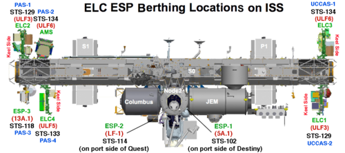
Orbital replacement units (or on-orbit replaceable unit[1]: 21 ) (ORUs) are key elements of the International Space Station that can be readily replaced when the unit either passes its design life or fails. ORUs are parts of the main systems and subsystems of the external elements of the ISS, none are intended to be installed inside the pressurised modules. Examples of ORUs are: pumps, storage tanks, controller boxes, antennas, and battery units. Such units are replaced either by astronauts during EVA or by the Dextre (SPDM) robotic arm. All are stored on the three external stowage platforms (ESPs) or the four ExPRESS Logistics Carriers (ELCs) mounted on the Integrated Truss Structure (ITS).
Introduction edit

While spare parts/ORUs were routinely brought up and down during the ISS life-time via Space Shuttle resupply missions, there was a heavy emphasis[clarification needed] once the Station was considered complete.
Several Shuttle missions were dedicated to the delivery of ORUs using support carrier structures/pallets of which some remained in the cargo bay, some that were deployed and retrieved and other pallets that were designed to be removed from the payload bay by RMS and placed onto the station.
Deployable pallet flights included STS-102[2] with External Stowage Platform ESP-1, STS-114[3] with ESP-2, STS-118[4] with ESP-2, STS-129[5] with ExPRESS Logistics Carrier ELC-1 and ELC-2, STS-133[6] with ELC-4 and STS-134[7] with ELC-3.
Other modes of ORU delivery included:
Payload bay sidewall mounted ORUs, such as BCDUs, were regularly carried and transported to the ISS via EVAs.
Also, three flights of the Integrated Cargo Carrier (ICC) which remained in the cargo bay on flights STS-102, STS-105 and STS-121; one use of the ICC-Lite on STS-122 (a shortened version of the ICC); two uses of the ICC-Vertical Light Deployable on STS-127 as ICC-VLD and STS-132 as ICC-VLD2, which were deployed and retrieved during the mission; and five uses of the Lightweight MPESS Carrier (LMC) on STS-114, STS-126, STS-128, STS-131 and STS-135, the LMC was not designed to be deployed and remained in the shuttle payload bay throughout the flight.
To date other than the Space Shuttle missions, only one other mode of transportation of ORUs was utilised by the station, the Japanese cargo vessel HTV-2 delivered an FHRC and CTC-4 via its Exposed Pallet (EP),[8] and HTV-4 delivered a Main Bus Switching Unit (MBSU) and a Utility transfer assembly (UTA).[9]
Modes of ORU transport to the ISS edit
-
 Main Bus Switching Unit (MBSU) ORU on the payload bay sidewall during STS-120
 -
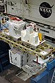
 ESP-2 platform mounted to the Quest module (pallet deployed)
 -
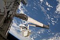
 ELC-3 in the grasp of Endeavour's robotic arm STS-134 (pallet deployed)
 -
 ICC in the forward end of the payload bay STS-102 (retained in the payload bay throughout the flight)


-
 ICC-Lite payload structure STS-122 (retained in the payload bay throughout the flight)
 -
 ICC-VLD on the RMS during STS-127 (pallet deployed and retrieved)
 -
 LMC at the back of the payload bay STS-131 (retained in the payload bay throughout the flight)
 -
 HTV-2 Exposed Pallet with FHRC and CTC4 during preflight (pallet deployed and retrieved)


Types of ORUs edit
Orbital replacement units are parts of the main systems and subsystems of the external elements of the ISS. Affecting the control of the cooling system, the movement and control of the solar arrays and SARJ as well as the flow of power throughout the station from solar arrays to the heat rejection system as part of the External Active Thermal Control System (EATCS). As well as storage tanks for oxygen as part of the station Environmental Control and Life Support System (ECLSS). ORUs can be hardware such as radiators, or simply batteries or communication antennas, essentially any element that can readily be removed and replaced when required.
The replaceable modular nature of the station allows its life to be extended well beyond its initial design life, theoretically.
ORUs and robotic arms edit
ORUs to be handled by Dextre have attachments designed to be gripped with the ORU/Tool Changeout Mechanisms (OTCM) on the end of each arm. The H‐fixture is for massive objects and/or to stabilize Dextre, the most common is a Micro‐fixture (also known as a Micro‐square) and the Micro‐Conical Fitting is used in tight spaces. A Modified Truncated Cone (MTC) Target is used to visually line up Dexter's arm to grab a fixture.[1] Any ORU with a grapple fixture can be moved by the Canadarm2.
Orbital replacement unit (ORU) spares edit
(Weight, description and current location of the spare on the station) edit
Multiple spares edit
- Flex Hose Rotary Coupler (FHRC) weight approx. 900 lb × 1 unit each on S1 & P1 Truss. The FHRC provides the transfer of liquid ammonia across the Thermal Radiator Rotary Joint (TRRJ) between the P1 (FHRC SN1001) & S1 (FHRC SN1002) truss segments and the Heat Rejection System Radiators (HRSRs).
Three spares – ESP-2 FRAM-7 (keel side) FHRC SN1003,[3] ESP-3 FRAM-2 (top side) FHRC SN1004,[10] ELC-4 FRAM-5 (keel side) FHRC SN0005 delivered by HTV-2.[8]
- Pump Module (PM) weight 780 lb x 1 unit each on S1 (current PM SN0006) & P1 (original PM SN0001 still in situ) Trusses. The PM is part of the station's complex External Active Thermal Control System (ETCS), which provides vital cooling to internal and external avionics, crew members, and payloads. The station has two independent cooling loops. The external loops use an ammonia-based coolant and the internal loops use water cooling.
Four original spares. Two unused Pump Modules remain – ELC-1 FRAM-7 (keel side) PM SN0007,[5] ESP-2 FRAM-1 (top side) PM SN0005.[5][11] Two utilised – ELC-2 FRAM-6 (keel side) PM SN0004 (Installed on ESP-2 FRAM-1 during STS-121, then removed by the Exp 24 crew to replace the failed original PM SN0002 on the S1 truss. SN0002 was returned to earth by the STS-135 crew. SN0004 replaced by PM SN0006 and moved to MT POA by Exp 38 crew in Dec. 2013. Relocated to ESP-2 FRAM-1 by ISS-41 EVA-27 in Oct. 2014. Swapped positions with SN0005 by SPDM in Mar. 2015.); ESP-3 FRAM-3 (top side) PM SN0006 (Installed on ESP-3 FRAM-3 during STS-127, swapped with failed PM SN0004 from S1 truss by Exp 38 crew Dec. 2013).
- Ammonia Tank Assembly (ATA) weight 1,702 lb x 1 unit each on S1 (now ATA SN0004) & P1 (now ATA SN0002) trusses. The primary function of the ATA is to store the ammonia used by the external thermal control system (ETCS). The major components in the ATA include two ammonia storage tanks, isolation valves, heaters, and various temperature, pressure, and quantity sensors. There is one ATA per loop located on the zenith side of the Starboard 1 (Loop A) and Port 1 (Loop B) truss segments. The ATA contains two flexible, chambers incorporated into its ammonia tanks that expand as pressurized nitrogen expels liquid ammonia out of them.
Two spares – ELC-1 FRAM-9 (keel side),[5] ELC-3 FRAM-5 (keel side)[7] Also note – other than these two spares, two other Shuttle missions brought up new ATAs and then returned the failed ATAs: STS-128 ATA SN0004 up/SN0002 down (P1 truss original ATA) and STS-131 SN0002 up/SN0003 down (S1 truss original ATA).
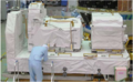
- Nitrogen Tank Assembly (NTA) weight 550 lb each × 1 unit each on S1 (now NTA SN0005) & P1 truss (now NTA SN0004). The NTA provides a high-pressure gaseous nitrogen supply to control the flow of ammonia out of the ATA.
Two spares – ELC-1 FRAM-6 (keel side) NTA SN0002 (refurbished)[5] ELC-2 FRAM-9 (keel side) NTA SN0003 (refurbished)[5] Also note – other than these two spares, two other Shuttle missions replaced NTAs. STS-122 delivered new NTA SN0004 and then returned the depleted P1 Truss NTA SN0003. STS-124 swapped the new NTA SN0005 from ESP-3 FRAM 2 with the depleted NTA SN0002 from the S1 Truss. The STS-126 crew returned this depleted NTA.
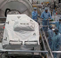
- High-Pressure Gas Tank Assembly (HPGTA) weight 1,240 lb x 5 units on quest. High-pressure oxygen and nitrogen gas tanks on board the ISS provide support for EVA and contingency metabolic support for the crew. This high-pressure O2 and N2 is brought to the ISS by the high-pressure gas tanks (HPGT) and is replenished by the Space Shuttle.
One spare – ELC-3 FRAM-6 (keel side),[7] one depleted tank ELC-2 FRAM-4 (top side)[5] Note the depleted tank was swapped with the original HPGTA launched on ELC-2 at FRAM-4.
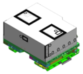
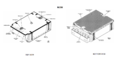
- Cargo Transport Container (CTC) each can weigh between 1,000 and 1,300 lb A container used to transport smaller ORUs such as Remote Power Control Modules in bulk, which may also be used during EVA or by the SPDM. NASA purchased 5 CTCs for such deliveries.
Three units – CTC-3 formerly on ELC-2 FRAM-2 (top side),[5] was later moved to ESP-2 FRAM-3 via SPDM. CTC-2 on ELC-4 FRAM-2 (keel side),[8] CTC-5 on ELC-3 FRAM-1 (top side)[7]
- Pitch/Roll-Joint (P/R‐J) x 2 units on the SSRMS. A Wrist joint with several degrees of freedom, designed to be replaced on orbit if required.
Two spares – ESP-3 FRAM-1 (top side),[4] ESP-2 FRAM-5 (keel side)[3]
- Control Moment Gyroscope (CMG) weight 600 lb × 4 units on Z1 Truss (two CMGs have been replaced, one by the STS-114 crew and a second by STS-118 crew). A CMG consists of a single-piece 25-inch diameter, 220-pound stainless steel flywheel that rotates at a constant speed of 6,600 rpm and develops an angular momentum of 3,600 ft-lb-sec (4,880 N-m-s) about its spin axis. The CMGs can also be used to perform attitude maneuvers. The CMGs rely on electrical power provided by the solar powered electrical subsystem.
Two spares – ELC-1 FRAM-5 (top side) CMG SN104,[5] ELC-2 FRAM-5 (top side) CMG SN102[5] Note: STS-118 crew delivered a CMG on ESP-3, swapping it for a failed unit on the ITS-Z1 truss. That failed unit was placed on ESP-2 FRAM-5 until it was returned by STS-122.[12]
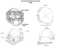
- S-band Antenna Support Assembly (SASA) weight 256 lb each × 2 active units and one other spare on ISS. The SASA consists of the assembly contingency radio frequency group (RFG, or ACRFG), SASA boom and avionics wire harness.
Two spares – ELC-3 FRAM-4 (top side),[7] ELC-3 FRAM-7 (keel side)[7]
- Direct Current Switching Unit (DCSU) weight 218 lb x 2 units each on the 4 IEAs. The DCSU routes battery power to the MBSU distribution bus to satisfy power demands. In addition to primary power distribution, the DCSU has the additional responsibilities of routing secondary power to components on the PV modules.
Three spares – ESP-1 FRAM-2,[2] ESP-2 FRAM-2 (top side),[3] ELC-2 FRAM-2 (top side)[3]
- Battery Charge/Discharge Unit (BCDU) weight 235 lb × 6 each on each of the 4 IEAs. The BCDU is a bidirectional power converter that serves a dual function of charging the batteries during solar collection periods (isolation) and providing conditioned battery power to the primary power buses during eclipse periods.
Two spares – ESP-3 FRAM-6 (keel side),[4] ELC-1 FRAM-4 (top side)[5]
- Main Bus Switching Unit (MBSU) weight 220 lb × 4 units on S0 Truss. The MBSUs act as the distribution hub for the EPS system. The four MBSUs on board the ISS are all located on the starboard zero (S0) truss. Each of MBSU receives primary power from two power channels and distributes it downstream to the DDCUs.
Two spares – ESP-2 FRAM-4 (top side), ESP-2 FRAM-6 (keel side). First spare launched with ESP-2 (FRAM-4) on STS-114, July 2005. Second spare launched on STS-120, October 2007, installed on ESP-2 FRAM-6. First spare swapped for failed 1A/1B MBSU by Expedition 32 crew in August 2012; the failed MBSU was initially stored on ESP-2 FRAM-4, then moved to ELC-2 FRAM-1 in January 2013. Third spare delivered by HTV-4 in August 2013, installed on ESP-2 FRAM-4. 2A/2B MBSU failed and was replaced by Dextre with third spare in May 2017. Failed 2A/2B unit was brought inside via JEM airlock in August 2017, repaired, returned to ESP-2 FRAM-4 in November 2017. 3A/3B MBSU failed in April 2019 and was replaced in May by the repaired former 2A/2B MBSU, with the 3A/3B unit stored on ESP-2 FRAM-4. Former 1A/1B unit brought inside and repaired in August 2019, then swapped into ESP-2 FRAM-4 for the former 3A/3B unit, which was brought inside in September 2019 and returned to Earth on board SpaceX CRS-19.
- Utility Transfer Assembly (UTA) a processor that allows power, signals and data to flow across the SARJ by roll rings incorporated within.
Two spares – ESP-2 FRAM-8 (keel side)[3] ELC-4 FRAM-4 (keel side) Utility Transfer Assembly (delivered by HTV-4 EP via SPDM Aug. 2013)
- Pump Flow Control Subassembly (PFCS) weight 235 lb Each external loop contains a pump and flow control system (PFCS) which contains most of the controls and mechanical systems that drive the EATCS. There are 2 pumps per PFCS which circulate ammonia throughout the external coolant loops. There are 2 on each IEA (x4) for a total of 8 active units.
Three original spares, now two available spares – ESP-1 FRAM-1[2] plus 2 on ITS-P6 that were initially used by the Early External Active Thermal Control System (EEATCS). One EEATCS spare on ITS-P6 swapped out for a leaky unit on the 2B power channel during an Exp 35 EVA May 11, 2013. Other EEATCS spare developed electrical fault and was replaced by an additional spare launched on SpaceX CRS-14.
-
 Flex hose rotary coupler (FHRC)
 -
 FHRC without MLI cover and in situ on the TRRJ
 -
 Pump module (PM)
 -
 PM drawing
 -
 Ammonia tank assembly (ATA)
 -
 ATA drawing (cover removed)


-
 Nitrogen tank assembly (NTA)
 -
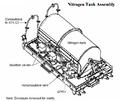 NTA drawing (cover removed)
 -
 HPGT being installed onto the ISS
 -
 HPGTs on the SL pallet drawing
 -
 Cargo transportation container (CTC-2)
 -
 Inside a CTC box


-
 Pitch/roll joint (P/R J)
 -
 P/R J drawing
 -
 Control moment gyroscope (CMG)
 -
 CMG drawing (cover removed)
 -
 S-Band antenna support assembly (SASA)
 -
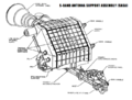 SASA drawing


-
 Direct-current switching unit (DCSU)
 -
 DCSU drawing
 -
 Battery charge/discharge unit (BCDU)
 -
 BCDU drawing
 -
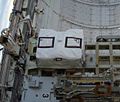 Main bus switching unit (MBSU)
 -
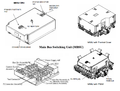 MBSU drawing
 -
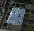 Pump flow control subassembly (PFCS)
 -
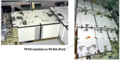 PFCS MLI removed
 -
 Utility transfer assembly (UTA) right-hand corner of this photo
 -
 Utility Transfer Assembly UTA preflight


Single spares edit
- Mobile transporter trailing umbilical system-reel assembly (MT TUS-RA) weight 354 lbs. at ELC-2 FRAM-8 (keel side)[5] x 1 unit on MT
The TUS reel assembly (TUS-RA) is basically a large spool much like a garden hose reel that pays out cable when the MT moves away and rolls it back up as the MT returns to the center of the truss. This is the same TUS-RA retrieved during STS-121. It was replaced and this failed unit was returned to earth and refurbished to later fly on ELC-2.
- Latching End Effector (LEE) weight 415 lbs. at ELC-1 FRAM-1 (top side)[5] x 3 units on ISS (Two on Canadarm2 and one on Dextre (SPDM) body)
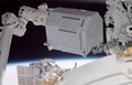
- Special-purpose dextrous manipulator (SPDM) arm at ELC-3 FRAM-2 (top side)[7] x 2 arms on SPDM
- Heat Rejection System Radiator (HRSR) weight 2,475 lbs. at ELC-4 (top side)[6] x 3 units each on S1 & P1 Truss
The Heat Rejection Subsystem (HRS) consists of a base, eight panels, torque panel, torque arm, an interconnected fluid system, a scissors-type deployment mechanism and a computer controlled motor/cable deployment system. Part of the station's external active thermal control system (EATCS), the HRS radiator rejects thermal energy via radiation.
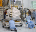
- Linear Drive Unit (LDU) weight 255 lbs. at ESP-3 FRAM-4 (top side)[4] x 1 on the MT
The LDU provides drive and stopping forces for the mobile transporter along the integrated truss structure rail.
- Space-to-Ground ANTenna (SGANT) weight 194 lbs. at ESP-3 FRAM-5 (keel side) x 2 units on Z1 Truss
- Plasma Contactor Unit (PCU) weight 350 lbs. at ELC-1 FRAM-2 (top side)[5] x 2 units on the Truss
Plasma Contactor Unit (PCU) is used to disperse the electrical charge that builds up by providing an electrically conductive "ground path" to the plasma environment surrounding the ISS. This prevents the electrical discharges and provides a means of controlling crew shock hazard during EVA. There are two PCUs located on the ISS Zenith 1 Truss, both of which are operated during EVA.
-
 Trailing umbilical system-reel assembly (TUS-RA)
 -
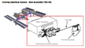 TUS-RA drawing
 -
 Latching end effector (LEE)
 -
 LEE drawing
 -
 Special-purpose dextrous manipulator (SPDM) arm
 -
 SPDM Arm drawing


-
 Heat rejection system radiator (HRSR)
 -
 HRSR drawing
 -
 Linear drive unit (LDU) carried by an astronaut
 -
 LDU drawing (cover removed)
 -
 Space-to-ground antenna (SGANT)
 -
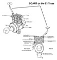 SGANT drawing


-
 Plasma contactor unit (PCU)
 -
 PCU drawing


See also edit
- Electrical system of the International Space Station
- Environmental control and life support system (ECLSS)
- ExPRESS Logistics Carrier (ELCs) STS-129 ELC-1 & 2, STS-133 ELC-3, STS-134 ELC-4
- External stowage platform (ESPs) STS-102 ICC & ESP-1, STS-114 ESP-2 & LMC, STS-118 ESP-3
- Integrated cargo carriers (ICCs) STS-105 ICC, STS-121 ICC, STS-122 ICC-Lite, STS-126 LMC, STS-127 ICC-VLD, STS-128 LMC, STS-131 LMC, STS-132 ICC-VLD2, STS-135 LMC
- Integrated Truss Structure (ITS)
- Scientific research on the International Space Station
References edit
- ^ a b Robotic Transfer and Interfaces for External ISS Payloads. 2014
- ^ a b c "STS-102 Presskit" (PDF).
- ^ a b c d e f "EVA Checklist: STS-114 Flight Supplement" (PDF).
- ^ a b c d "STS-118 Presskit" (PDF).
- ^ a b c d e f g h i j k l m n L. D. Welsch (October 30, 2009). "EVA Checklist: STS-129 Flight Supplement" (PDF). NASA.
- ^ a b "Space Shuttle Mission: STS-133" (PDF). NASA. February 2011.
- ^ a b c d e f g "Space Shuttle Mission: STS-134" (PDF). NASA. April 2011.
- ^ a b c "HTV2: Mission Press Kit" (PDF). Japan Aerospace Exploration Agency. January 20, 2011.
- ^ "HTV4 (KOUNOTORI 4) Mission Press Kit" (PDF). Japan Aerospace Exploration Agency. August 2, 2013. Retrieved June 19, 2015.
- ^ EVA Checklist STS-126 Flight Supplement, 2008
- ^ "ISS Daily Summary Report – 03/06/15". ISS On-Orbit Status Report. Retrieved 30 March 2018.