


Summary
A whistle is a device that makes sound from air blown from one end forced through a small opening at the opposite end. They are shaped in a way that allows air to oscillate inside of a chamber in an unstable way. The physical theory of the sound-making process is an example of the application of fluid dynamics or hydrodynamics and aerodynamics. The principles relevant to whistle operation also have applications in other areas, such as fluid flow measurement.
Types edit
Wilson, et al., in their study of human whistling[1] (see below), pointed out the importance of including the symmetry or asymmetry of the unstable flow in addition to the feedback classes listed below. Because of the close relationship of flow symmetry to the sound field generated, their concept was included here as part of the sound source description (monopole – symmetric and dipole – asymmetric).
Monopole edit

Whistles that generate sound through fluctuations of mass flow across a boundary are called monopole-like sources. The figure on the right is an example of a small sphere whose volume is oscillating. For this type of source, the sound is emitted radially, so the sound field is the same in every direction and decays with the inverse square of the distance. The sound power can be expressed as:

The variables U and L are considered characteristic of the source, and their correct choice is important.
Dipole edit

Whistles that generate sound through fluctuations of momentum or stress and strain of a force exerted on the surrounding medium are called dipole-like sources. The figure on the right is an example of a small rigid sphere that is moving back and forth in a given direction. This results in a non-uniform sound field. The sound power can be expressed as:

Feedback categories edit
Aerodynamic whistles rely on the instability of flows and feedback that enhances the instability. There are several ways that feedback can occur.[2]
Category I edit
The sound from a whistle in this category is primarily a byproduct of source motion. The back reaction is insufficient to strongly control source motion, therefore whistles are not in this category.
Category II edit
The back reaction of the medium is a determinant of source motion. Unstable fluid motion or the sound generated by it can feedback to the source and control it. What is required is:
- a source of steady power;
- an amplification mechanism that can convert the steady power to time-varying power;
- a disturbance, which supplies the oscillations to be amplified;
- a means of generating sound or other oscillatory fluid Brownian motion;
- a means for feedback of that oscillatory motion as a disturbance to the input of the amplifier.
Whistles are in this category. There are several ways to describe the feedback process.
Class I edit
The feedback is essentially incompressible; the speed of sound, although finite, is sufficiently large that it can be considered infinite. This action may be called hydrodynamic feedback. There are a number of class I devices.
Class II edit
The feedback is compressible and does not depend on the speed of sound. This action may be called quasi-compressible feedback.
Class III edit
The feedback is compressible and depends on the speed of the sound. This may be called acoustic feedback.

The figure on the right shows a block diagram of these feedback mechanisms. All aerodynamic whistles operate under one of the classes.
Stages edit

Feedback in whistles is nonlinear mechanics or chaos. Because of the non linearity, it is possible to have more than one frequency at a given flow rate. The difference depends on whether the flow rate is achieved by increasing the flow or by decreasing the flow. The possibility of multiple states is called a stage and is shown schematically in the figure on the right. As the flow speed increases (Reynolds number, Re) the frequency slowly climbs (nearly constant Strouhal number, St) but then the frequency jumps up abruptly to a higher stage. As the flow speed is later decreased, the frequency slowly decreases but then jumps down abruptly to a lower stage. This pattern is called a hysteresis loop.
Higher stages are associated with more vortices in that distance, hinting that this distance can be an important characteristic dimension. In several whistles, three stages have been identified. Overblowing in some musical wind instruments causes stage I to jump to stage II.
Flow instability edit

Flow instability is the engine for whistles. It converts steady energy to time-dependent energy.
An example is shown in the figure on the right with a water jet.[3] The laminar two-dimensional jet amplifies small disturbances at the orifice to generate a vortex street. For this case, the flow speed, in terms of Reynolds number, was graphed against the disturbance frequency, in terms of the Strouhal number for a variety of disturbance amplitudes to reveal the region of instability as shown in the figure on the left. The value of D in the figure represents the ratio of the lateral disturbance displacement to the nozzle width; the disturbances were minute.
One important source of instability in a fluid is the presence of a velocity gradient or shear layer with an inflection point. In a whistle, the instability starts at some point in the three-dimensional region and then moves along some path in that region as the local variables change. This makes a comprehensive understanding of whistle instability mechanisms very difficult.
Scaling edit
Whistles come in all shapes and sizes, but their operation can be unified through the concepts of dynamic and geometric similarity using dimensional analysis. Nature knows nothing of the specific measurement systems we use; it cares only about ratios between the various forces, time scales, and several dimensions. To compare them, we need to take into account the established ratios that are relevant to whistle operation.
The similarity is best exposed by determining a speed U, that is, characteristic of the dynamics, and a dimension L, that is, characteristic of the geometry. If these values are used in dimensionless numbers, such as those listed below, much understanding of the phenomenon can be achieved.
Strouhal number edit

The first number is the ratio of unsteady inertial forces to steady inertial forces. The number was named in honor of Vincenc Strouhal, who first deduced the relationship between the vortex shedding frequency around a cylinder and the flow speed. The characteristic variables were the cylinder diameter L1 and the speed U of the flow over it.
This number permits relationships to be developed between the different sizes and speeds. This equation may be referred to as a fluid mechanical Strouhal number in comparison with the second version, which may be referred to as the acoustical Strouhal number. The first version is used for the dynamic similarity of the fluid motion in whistles, while the second version is used for the dynamic similarity of the acoustical motion in whistles. Many whistles require the use of both numbers.
Mach number edit

It is the ratio of the steady speed to the speed of sound. The number was named in honor of Ernst Mach, who first studied (among other things) supersonic flow and shock waves. This number describes the range between flows that can be considered in compressible and flows that compress
Reynolds number edit

It is the ratio of the steady inertial forces to the steady viscous forces. The number was named in honor of Osborne Reynolds, an engineer who did pioneering studies on the transition of laminar to turbulent flow in pipes.
Rossby number edit

It is the ratio of linear velocity to tangential velocity for swirl flows. The frequency is characteristic of the rotation rate of the flow. The number was named in honor of Carl-Gustaf Rossby, a meteorologist who first described the large-scale motions of the atmosphere in terms of fluid mechanics.
Dimensionless force edit

The ratio of the actual dynamic force to the steady momentum and steady current density.
Dimensionless volumetric flow rate edit

The ratio of the dynamic volumetric flow rate to the steady volumetric flow rate.
Monopole-like whistles edit
In these whistles, the flow instability is symmetric, often resulting in periodic ring vortices, and the sound generation is associated with fluctuations in volumetric/mass flow rates.
Hole tone (teapot whistle, bird call) edit


The steady flow from a circular orifice can be converted to an oscillatory flow by adding a downstream plate with a circular hole aligned with the orifice. Small perturbations in the flow at the hole feedback to the orifice cause a variable volumetric flow rate through the downstream hole because of the symmetry of the feedback. The disturbance in the jet is a symmetric vortex ring that moves at some speed slower than the mean jet speed until it encounters the hole, and some fluid is forced through it, resulting in a monopoly-like sound field in the half-space outside. The figure on the right shows a schematic of the geometry.
To invoke dynamic similarity,[4] the characteristic speed in a study was chosen to be the average speed U of the jet at the orifice and the characteristic length was chosen to be the orifice diameter δ. Tests were made at five spacing distances h/δ from the orifice. Two scaling laws were used: the Strouhal number was graphed as a function of the Reynolds number. The results are shown in the figure on the right.
The frequency of the tone is determined by how often a vortex encountered the hole while moving at some speed u less than the initial jet speed. Since the jet slowed as it proceeded toward the hole, the speed of the vortex slowed with it, so the frequency and Strouhal number were greater at closer spacing. The Strouhal-number data showed clearly the almost linear relation between frequency and initial jet speed. In four of the distances tested, there were jumps between stage I and stage II. The hysteresis loops are clear indications of the complex nature of the jet instability gain structure.
The uniformity of the measured sound field for this whistle confirmed its monopole-like nature. Measurements of speed dependence of the sound level showed it to be very close to U4, further confirming the monopole nature of the source. At these speeds and spacing, the feedback was normally class II, but reflecting surfaces as far away as 3 meters and with proper phasing, controlled the tone, converting the feedback to class III.
The hole tone is also known as the teapot whistle.[5] They found that above a Reynolds number of 2000, hole tone operation occurred with symmetric vortex evolution and a constant Strouhal number with Reynolds number. At lower speeds, the cylindrical volume responded as a Helmholtz resonator. Baron Rayleigh[6] was aware of this whistle; it was called the bird call then. In Australia, there is the Tenterfield fox whistle[7] and the traditional fox whistle that appear to operate as hole tones.
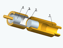
Corrugated pipe whistle edit

This whistle has dozens of popular names. Corrugated tubes or pipes are often used in various applications because they are easier to bend than traditional pipe. Steady flow through a corrugated pipe at low Reynolds numbers results in a fluctuating volumetric flow rate that generates a monopoly-like sound field at the pipe exit. Examples of such pipes are shown in figure on the right.
The yellow plastic pipe shown in the image is a toy that whistles when the pipe is whirled around. The metal pipe shown was used in the Concorde cockpit to provide cooling air to the pilots, but it was removed due to its loud tone. This whistle is similar in many respects to the hole tone, in particular the teapot whistle. It is subject to frequency jumps and hysteresis loops. There are numerous articles on the Internet about this whistle, and it has been studied in academic literature.[8][9][10]
The characteristic speed is the mean flow U through the pipe and the characteristic length must be a multiple of the spacing L between corrugations, nL, where n is an integer number. At low speeds, the unstable interior flow needs to travel several corrugations to establish the feedback loop. As the speed increases, the loop can be established with fewer corrugations. Simple tests were performed on the yellow plastic tube.
The Strouhal number

was used as the scaling factor. The highest frequency (7554 Hz) was found in the "overblown" condition, and n was presumed as one corrugation. At the least flow rate, the frequency of 2452 Hz compared favorably to n = 3. At intermediate flow rates, several non-harmonically related frequencies occurred simultaneously, suggesting that several corrugations were involved in the sound generation. In the smaller metal tube, a predominant tone appeared at 6174 Hz and corresponded to n = 2. A unique aspect of this whistle is that the internal flow carries both the unstable vortex downstream and the returning feedback signal upstream.
Pipe tone (Pfeifenton) edit

The unique feature of this whistle is that the tone sounds only with flow through the orifice from outside; it is an acoustical diode. A cylindrical cavity with a small circular, square-edged hole at one end and totally open at the other is known to generate a tone when air is passed through it. It is subject to frequency jumps and hysteresis loops similar to the hole tone. There appear to be two stages, and the feedback is likely class II if the tube is short. The fundamental tone occurs near λ = 4L, so one characteristic dimension is L, the length of the tube. The characteristic speed U is that of the flow through the hole.
A monopole-like sound field is generated by volumetric flow rate oscillations. Karthik[11] and Anderson[12][13][14] have studied this phenomenon and concluded that symmetric vortex shedding on the cavity side is the driving agency.
An example of this device is shown in the figure on the right; it had a 0.125 in (3.2 mm) diameter hole, was 1.9 in (48 mm) long, and 0.8 in (20 mm) in diameter. The quarter-wave resonance was calculated to be 1780 Hz, while the measured fundamental was 1625 Hz with detectable second and third harmonics. End corrections for radiation from the openings is needed to bring the two frequencies in consonance. To determine the end corrections, two additional dimensions are needed: the diameter d1 of the orifice and the diameter d2 of the tube.
Hartmann, Galton whistles (stem jet) edit

While the previous whistles occur at low flow speeds, this whistle occurs at very high speeds. When a subsonic jet impinges on a cavity, jet instability becomes part of the feedback loop as with the hole tone. When a supersonic jet impinges on a cavity, acoustic shock wave instability becomes part of the feedback loop. The figure on the right is one example of this whistle. A cylindrical cavity with one end open and facing the supersonic circular jet will result in extremely intense sound. The shapes in the figure represent the shock/expansion cells within the jet. A related configuration, called the stem jet, has a central rod in the jet that extends to support and align the cavity. There are several of other geometric variations, all of which operate in similar fashion, such as the steam whistle.
These devices have been studied,[15] and reviewed by Raman.[16] Here we look primarily at the Hartmann whistle. The shock cells of the jet interact with the shock in front of the cavity (the flow in the cavity being subsonic). Small symmetric disturbances in the jet stream are amplified as they proceed toward the cavity (similar in some respects to the hole tone), causing the shock in front of the cavity to oscillate. The shock front acts much like a piston source of high energy, resulting in a monopole-like sound field. Again, the volumetric flow is directional, unlike the theoretical monopole.
The sound field may be similar to that created by oscillatory flow from a pipe, except for presence of the supersonic jet structure, which can strongly modify the directivity. The original equation of Hartmann is shown below:

The diameter of the orifice and cavity is d, the distance between orifice and cavity is h, and the orifice pressure P was given in kilograms force per meter squared (1 kgf/m2 ≈ 9.8 Pa). At the lower limit of h the second term disappears. In this case, the equation could have been reformatted in terms of the acoustical Strouhal number, as shown in the second equation above. The characteristic speed U at the nozzle is the sound speed c0. It is interesting that the number is very close to that found by Strouhal for flow over a cylinder. There are two characteristic length scales. Nozzle diameter d characterizes the sound power, while the separation distance h characterizes the frequency.
Comprehensive studies of this phenomenon[17][18] have shown that the position of the cavity is critical in creating sound. The process has hysteresis loops, and the frequencies are related to multiples of the quarter-wavelength resonance of the cavity. After reformatting Hartmann's formula, and using the new formulation above, an equation for sound power can be written as

Since the characteristic speed U and sound speed are essentially the same, it can be rewritten as the second equation. This equation has the same structure as the one for the point monopole shown above. Although the amplitude factor A replaces the dimensionless volumetric flow rate in these equations, the speed dependence strongly confirms the monopole-like characteristics of the Hartmann whistle. A cousin to the Hartmann whistle is shown in the figure on the right, the Galton whistle. Here the cavity is excited by an annular jet, which oscillates symmetrically around the sharp edges of the cavity. It appears to be a circular version of the edge tone (discussed below) in which the symmetry of the otherwise dipole source of the edge tone is converted to a monopole source.
Since it is highly likely that the oscillations are coherent around the periphery, there should be a fluctuating volumetric flow rate from the cavity with only a small net lateral force. Thus the source is yet another version of a monopole-like geometry; the volumetric flow rate is a cylindrical area between the jet and cavity.
Rijke tube edit

There are several whistle phenomena in which heat plays a role. The temperature in a sound wave varies, but since this variation is so small, normally it is common to neglect its effects. However, when amplification can occur, a small variation can grow and have important influence on the sound field created. The most well known thermal whistle is the Rijke tube, a vertical tube with a heated gauze material placed inside.
Originally, the gauze was heated with a Bunsen burner; later, a wire grid was heated electrically. The heat transferred to the air in the tube sets it into near half-wave resonance if the gauze is placed below the midpoint of the tube as shown in the figure on the right. There is no theoretically optimal position, as the wave speed upward is c0+u, the convection speed, while the wave speed downward is c0−u. Without a convection flow, the midpoint and the lower tube end are the best locations for heat transfer. With convection, a compromise position halfway between the two points is normally chosen, which depends on the amount of heat added. One characteristic length associated with frequency is tube length L.
Another characteristic length associated with sound power is αL, the position of the gauze. The characteristic speed must be the convection speed u at the heat source. For detailed study of the whistle, see Matveev.[19] Since the first mode resonance is about half-wave, the sound field emitted from the tube is from two in-phase monopole-like sources, one at either end. A gas flame inside a tube can drive resonance; it was called a singing flame. There is a reverse Rijke tube, where hot air passes through a cold grid.
Sondhauss and Taconis tubes edit
The Sondhauss tube is one of the early thermal tone generators; it was discovered in the glass-blowing industry. A bulb with hot air is connected to one end of a tube that is at room temperature. When the cold tube is blown, tube acoustic oscillations occur. It was discussed by Baron Rayleigh in his "Theory of Sound". This device is not considered a true whistle, since the oscillations decay as the temperatures equalize.
In analyzing this tube, Rayleigh noted that if heat had been added at the point of highest density in the sound wave and subtracted at the point of lowest density, the vibration would be encouraged. Another thermal effect is called the Taconis oscillation.[20] If a stainless steel tube has one side at room temperature and the other side in contact with liquid helium and superfluid helium, spontaneous acoustic oscillations are observed. Again, the Sondhauss tube is not a true whistle.
Human whistle edit

The number and variety of whistles created by humans is quite large, yet very little study has been done on human whistling from a physics perspective. There are three possible mechanisms: Helmholtz resonance, symmetric hole tone operation (monopole), or asymmetric edge tone operation (dipole).
Wilson and his colleagues[1] have simulated the human whistle by creating a cylinder 2.04 in (52 mm) in diameter with a rounded orifice at one end that supplied a jet and another rounded orifice at the other end of the same diameter and on the same axis. The geometry was very similar to that of the tea-pot whistle. After a number of tests at various speeds, orifice diameters, and orifice thicknesses, they concluded that the whistle was created by a Helmholtz resonance in the cylinder volume. There was enough data for one case in their study to calculate the Strouhal and Reynolds numbers. The results are shown in the figure on the right.
The Strouhal number was essentially constant over the limited speed range, suggesting hole tone operation with class I or class II feedback. Their work indicated symmetric unstable vortex flow, as would be expected, but there was no mention of stages. In the study by Henry Wood[citation needed], it was noted that Helmholtz resonance could occur at low speeds. The flexibility of the mouth suggests that although a hole-tone feedback mechanism is highly likely, the possibility of Helmholtz resonances in the mouth cavity and asymmetric edge tone actions with the teeth are considered possible.
Leaf whistle edit
The leaf can be used as a whistle which can produce up to three octaves. It is a popular instrument in many cultures, being called slek in Cambodia, 木叶 (Mù yè) in China, gum leaf in Australia, and Birkenblatt Blasen in Germany. Through use of a high speed camera one can see that the leaf moves away from the lips when the player blows and its elasticity brings it back onto the lip this oscillating movement sets it in vibration to produce a sound. An analysis of the overtone series comparing an oboe and birkenblatt playing the note F2 shows they are nearly identical.[21]
Dipole-like whistles edit
In these whistles, the flow instability is asymmetric, often resulting in rows of alternate vortices, and the sound generation is associated with fluctuations of applied force. The sound field is as close to a dipole source as local geometry allows.
Aeolian tone edit


The steady flow over a cylinder (or similar object) generates vortex shedding and consequent sound. The early Greeks used this phenomenon to develop a harp, and the sound was called an Aeolian tone after Aeolus, god of the wind.
Whistling telephone wires, automobile radio antennae, certain automobile front grilles, and smoke stacks are other examples of this tone. At very low Reynolds numbers, the flow around a cylinder is stable, forming two fixed vortices behind it. As the speed increases, the flow, although laminar, becomes unstable, and vortices are shed alternately.
Hydrodynamic feedback (class I) influences the formation of new vortices and exerts a fluctuating force on the cylinder. The flow field is shown in the upper figure on the right (created by Gary Koopman). Theodor von Karman[22] identified and analyzed the flow behind objects like a cylinder, and since then this special flow has been called the Karman vortex street. Vincenc Strouhal was the first to scientifically investigate the sound emitted by flow around a rigid cylinder. At low Reynolds numbers the tone was pure, and the frequency was proportional to the steady flow speed U and inversely proportional to the cylinder diameter d.
For many applications, the first equation below is often used. A review of the literature[23] produced the figure on the right for the Strouhal number. At low Reynolds numbers the Strouhal number rises as inertial effects begin to dominate and then decays slightly at higher numbers. The second equation below is a best fit for the data for 1000 < Re < 100000.


It is surprising how often oscillatory flow phenomenon have Strouhal numbers in this range. For shape comparison, the Strouhal number for an ellipse has been measured at 0.218, a cylinder at 0.188, a square at 0.160, and a triangle at 0.214. The characteristic dimension is that of the object lateral to the flow and the characteristic speed is that of the impinging flow.
The second equation suggests that the Strouhal number is a weak negative function of Reynolds number. This suggests that the dynamic similarity approximation is reasonable. The fluctuating force exerted on the cylinder is a result of the flow circulation around it caused by the alternate vortex separation as suggested in the third figure. The fact that the vortices are not directly behind the cylinder suggests that the force vector has both a lift and drag component, resulting in lift and drag dipoles.
An approximate way to relate the sound generated to the flow characteristics is to perturb the standard drag equation with velocity perturbations as shown in the upper equation below (lift measurements for cylinders are generally not available). The upper equation is the modified drag equation with both drag component u and lift component v and the cross-sectional area dL, where d is the cylinder diameter, and w is the length.


Manipulation of the equation yields the lower two equations for the dipole sound power of both lift and drag. Each time a vortex is shed, the drag velocity fluctuation u has the same sign, but the lateral velocity fluctuation v has opposite signs, since the vortex is shed on alternate sides. As a result, the drag dipole would be expected to have twice the frequency of the lift dipole.
Phillips[24] found the lateral velocity fluctuations were two orders of magnitude greater than the longitudinal, so the lift dipole is 20 dB above the drag dipole. He found the drag dipole did occur at twice the frequency of the lift dipole. At higher speeds, the vortex separation may not be correlated over the entire length of the cylinder, resulting in multiple essentially independent dipole sources and lower sound power. The lower figure on the right shows the correlation coefficient as a function of distance along the cylinder and is from the Etkin, et al. study.[citation needed]
Trailing-edge tone edit


The boundary layer on the airfoil of a glider is laminar, and vortex shedding similar to that of a cylinder occurs at the trailing edge. The sound can be a nearly pure tone.
The figure on the left shows a one-third octave band spectrum taken under a glider flyover; the tone is 15 dB above the broad band sound. The aircraft speed U was 51 m/s (170 ft/s), and the frequency was near 1400 Hz.
Based on a Strouhal number of 0.20, the characteristic dimension δ was calculated to be near 0.25 in (6.4 mm); the boundary layer thickness. A dipole sound field was created at the trailing edge due to the fluctuating force exerted on it.
At higher speeds on powered aircraft, the boundary layer on the airfoil is turbulent, and more complex vortex shedding patterns have been observed. Since it is difficult to measure in flight, Hayden[25] made static tests.
The figure on the right shows an example. A boundary layer flow was created on both sides of a thin rigid flat plate terminated with a square trailing edge. Note the nearly pure tone at 2000 Hz with a Strouhal number of 0.21 protruding above the turbulent sound spectrum. Once again, the magic number of Strouhal appears. The characteristic speed was the mean speed U of the jet, and the characteristic dimension was chosen as the trailing-edge thickness t. The better characteristic dimension would have been the boundary layer thickness, but fortunately the two dimensions were almost the same. The measured sound field was clearly dipole-like (modified slightly by the plate presence).
The lower figure on the right shows a number of turbulent sound spectra measured at various speeds.[26] The frequencies were Strouhal number scaled with U, and the sound levels were scaled with the dipole sound power rule of U6 over a speed range of 3 to 1. The data fit was quite good, confirming dynamic similarity and the dipole model. The slight discrepancy in level and frequency overlap suggests that both the dimensionless force and the Strouhal number had weak dependence on the Reynolds number.
Another characteristic dimension is the airfoil chord. In these tests the jet width was sufficient to keep the vortex shedding coherent across it. On an airfoil there would be a correlation length less than the wingspan, resulting in several independent dipoles arrayed laterally. The sound power would be diminished somewhat. Since the dipole model is based on the time rate of change of the force, reduction of sound power might be accomplished by reducing that rate. One possible means would be for the opposite sides of the surface to gradually sense each other spatially prior to the trailing edge and thus reduce the rate at the edge. This might be done by a section of graduated porous or flexible materials.
Circular-saw whistle edit

An edge tone occurs when a jet impinges on a fixed surface. A trailing edge tone occurs when an exterior flow passes over a trailing edge. There is a whistle that is a combination of an edge tone and a trailing-edge tone and might be called a wake-edge tone. It occurs in rotating circular saws under idling conditions and may be called the circular-saw whistle. Under load conditions, blade vibration plays a role, which is not addressed here.
There have been several studies of the fundamental sound generating mechanisms of this whistle.[27][28][29][30][31]
A drawing of typical blade construction is shown in the figure on the right. Research has shown that the sound field is dipole with the primary axis perpendicular to the blade plane. The sources are fluctuating forces acting on each cutting blade. Bies determined that the characteristic speed was the blade velocity RΩ, and the characteristic dimension was the tooth area. Other researchers used blade thickness as the characteristic dimension. Cho and Mote found that the Strouhal number St = fh/U was between 0.1 and 0.2, where h was the blade thickness. Poblete et al., found Strouhal numbers between 0.12 and 0.18. If the edge tone is relevant, perhaps the characteristic dimension should be the gap between the blades.
The researchers deduced that the fluctuating force was proportional to U2, but the sound power was found to vary from U4.5 to U6.0. If the measurement bandwidth is broad and the measurement distance is out of the near field, there are two dynamic factors (Strouhal number and dimensionless force), that can cause the exponent to be less than 6. Both the Deltameter and hole tone data show the Strouhal number is a weak negative function of Reynolds number, which is squared in the sound power equation. This would result in a reduced speed exponent. This factor is not likely to explain the large reduction in exponent however.
The blade geometry was highly variable in the tests, so it is likely that the negative dependence of the dimensionless force on Reynolds number is the major factor. This whistle has two features that separate it from the other whistles described here. The first is that there are a multiplicity of these dipole sources arrayed around the periphery, that most likely are radiating at the same frequency, but incoherently. The second is that blade motion creates a steady, but rotating, pressure field at each blade. The rotating steady force creates a rotating dipole field, which has an influence in the geometric near field. The feedback is class I (hydrodynamic), and there is no indication that stages other than stage 1 occur.
Ring tone edit


The word "ring" here refers to a toroidal shape. The flow from a circular orifice impinging on a toroidal ring of the same diameter as the orifice will result in a tone; it is called a ring tone. It is similar to the hole tone described above, except that because the plate was replaced by a ring, a fundamental change in the resultant sound field occurs. Small disturbances at the ring feed back to the orifice to be amplified by the flow instability (class I). The unstable flow creates a set of symmetric (ring) vortices that later impinge on the physical ring.
The passage of a vortex by the ring is shown schematically in the figure on the right in three steps. The flow vectors in the figure are merely suggestive of direction.
When two vortices are equidistant from the ring, one being beyond and the other approaching, the net circulation around the ring is zero; the null point for the flow oscillation. Each vortex creates a circular (ring) flow field whose axis varies slightly from the vertical as it passes. The figure suggests that the main component of the force on the physical ring is in the direction of the jet flow. If the vortex is a true ring (all parts are in phase), a dipole sound field directed along the jet axis is created.
The figure also suggests that there is a lateral component of force, which can only be interpreted as a weak radial dipole. Experiments have been performed on the ring tone.[4] The lower figure on the right shows the relationship of frequency to Reynolds number. If the Strouhal number were graphed instead of the frequency, it would have shown that contours were reasonably constant similar to those for the hole tone. Close examination of the data in the figure showed a slight negative dependence of Strouhal number on Reynolds number.
It appears that this whistle has only two stages. The sound field was measured and clearly indicated a dipole, whose axis was aligned with the jet axis. Since there were no reflecting surfaces near the source, the data also indicated that a weaker radial dipole component also existed. Such a field can only exist if there is a time delay at a distant point between each of the force components.
Vortex whistle edit


When the swirling flow within a pipe encounters the exit, it can become unstable. An example of the original system is shown in the figure on the left. The instability arises when there is a reversed flow on the axis.
The axis of rotation itself precesses around the pipe axis, resulting in a rotating force at the pipe exit and results in a rotating dipole sound field. Studies of this whistle[32][33] have shown that dynamic similarity based on the pipe diameter d as the characteristic length scale, and inlet mean flow speed U as the characteristic speed was not achieved, as shown in the lower figure on the right. A more correct speed would be that characteristic of the swirl fd, where f is the precession (and sound) frequency, based on the Rossby number. To test the relevance of this new characteristic speed, the flow rate was increased, and the frequency and level of the sound was measured. Using the dipole model, the calculated force was found to be nearly proportional to (fd)2, confirming the correctness of the new characteristic speed.
Measurements showed that the vortex whistle was created by a rotating asymmetric vortex, which created a rotating force vector in the plane of the exit and a rotating dipole sound field. The phenomenon of swirl instability has been shown to occur in other situations.[34] One was the flow separation on the upper side of delta-shaped airfoils of high-speed aircraft (Concorde). The angle of attack of the leading edge resulted in a swirl flow that became unstable. Another is the flow within cyclone separators; the swirling flow there occurs in an annular region between two tubes. The flow reverses at the closed end of the outer tube and exits through the inner tube. Under certain conditions, the flow in the reversal region becomes unstable, resulting in a period rotating force on the outer tube.
Periodic vibration of a cyclone separator would indicate vortex instability. Large centrifugal fans sometimes use radial inlet blades that can be rotated to control the flow into the fan; they create a swirling flow. At near shutoff, where the swirl is very high, rotating blade stall of the fan blades occurs. Although not researched, it is highly likely that swirl instability is the cause. The feedback is clearly hydrodynamic (class I), and there is no indication that more than one stage occurs.
Swirl meter edit

The method of creating swirl in the vortex whistle was considered the cause for lack of dynamic similarity, so the swirl was created in a pipe with a contraction having swirl blades followed by an expansion to create the required axial backflow. This was the vortex whistle in a pipe. Measurements made with this geometry are shown in the figure on the right. As can be seen, dynamic similarity was achieved with both air and water. This whistle became a flow meter called the swirl meter. Its accuracy rivals that of the vortex-shedding meters described above, but has a higher pressure drop. The feedback is hydrodynamic (class I), and only one stage was found.
Edge tone edit


When a rectangular jet impinges on a sharp-edged object such as a wedge, a feedback loop can be established, resulting in a nearly pure tone. The figure on the right shows schematically the circulation of two vortices as they pass the wedge. This simple diagram suggests that there is a force applied to the wedge, whose angle varies as the vortices pass.
As found in the Aeolian tone, the vertical component (lift) is large and results in a dipole-like sound field at the wedge (shown in the lower figure) and a much weaker horizontal component (drag) at twice the frequency (not shown). The drag component may contribute as part of the driving force for musical instruments (discussed below). A seminal study by Powell[35] of this phenomenon has exposed many details of the edge-tone phenomenon. He showed that this whistle has three stages, and the feedback loop was hydrodynamic (class I). A semi-empirical equation for the frequency, developed by Curle,[36] when converted to Strouhal number, is

This equation, applicable for h/d > 10, shows the mean speed U of the jet at the orifice as the characteristic speed and the distance h from orifice to the edge as the characteristic dimension. The integer n represents the various vortex modes. It also suggests that dynamic similarity is achieved to a first approximation; one deviation is that the speed at the wedge, which is less than that at the orifice, should be the characteristic speed. A weak negative Reynolds-number effect is likely. The orifice width d also has some influence; it is related to vortex size and lateral correlation of the shedding process.
The presence of a dipole sound field and a periodic force proportional to U2 was confirmed by Powell. Numerical simulations of the edge tone and extensive references can be found in a NASA report.[37] The lower figure on the right may be called a wake-edge tone. If the preferred frequencies of the trailing edge instability match the preferred frequencies of the free edge tone, a stronger dipole sound should arise. There does not appear to be any research on this configuration.
Shallow-cavity tone edit
The study of sound generated by flow over cavities at high speed has been well funded by the federal government, so a considerable amount of effort has been made. The problem relates to flow over aircraft cavities in flight such as bomb bays or wheel wells. Flow over a cavity in a surface can result in excitation of a feedback loop and nearly pure tones. Unlike the edge tone noted above, the cavity edge is typically square, but also can be an edge as part of a thin structural shell. Cavities can be separated into shallow or deep ones, the difference being that for deep cavities a class III (acoustical) feedback path may be controlling. Shallow cavities are addressed here and are those in which the cavity length L is greater than the cavity depth D.
At high speeds U, the flow is turbulent, and in some studies the speed can be supersonic, and the generated sound level can be quite high. One study[38] has shown that several modes of oscillation (stages) can occur in a shallow cavity; the modes being related to the number of vortices in the distance L. For shorter cavities and lower Mach numbers, there is a shear-layer mode, while for longer cavities and higher Mach numbers there is a wake mode. The shear-layer mode is characterized well by the feedback process described by Rossiter. The wake mode is characterized instead by a large-scale vortex shedding with a Strouhal number independent of Mach number. There is an empirical equation for these data; it is called Rossiter’s formula.
Lee and others[39][40] have shown it in Strouhal number form as

The bracketed term includes two feedback loop speeds: the downstream speed is the speed of the vortices u, and the upstream speed is that of sound c0. The various modes are described by an integer n with an empirical delay constant β (near 0.25). The integer n is closely related to the number of vortices en route to the edge. It is clear from shadowgraphs that the fluctuating force near the downstream edge is the sound source. Since the Mach number of the flow can be appreciable, refraction makes it difficult to determine the major axis of the dipole-like sound field. The preferred frequencies in shallow cavities are different from those for the edge tone.
Police whistle edit

It is commonly used to describe whistles similar to those used by police in America and elsewhere. There are a number of whistles that operate in the same manner as the police whistle, and there are number of whistles that are used by police elsewhere that do not operate in the same manner as the police whistle. The London Metropolitan police use a linear whistle, more like a small recorder. Police whistles are commonly used by referees and umpires in sporting events.
The cross-section of a common whistle is shown in the figure on the right. The cavity is a closed-end cylinder (3⁄4 in (19 mm) diameter), but with the cylinder axis lateral to the jet axis. The orifice is 1⁄16 in (1.6 mm) wide, and the sharp edge is 1⁄4 in (6.4 mm) from the jet orifice. When blown weakly, the sound is mostly broadband, with a weak tone. When blown more forcefully, a strong tone is established near 2800 Hz, and adjacent bands are at least 20 dB down. If the whistle is blown yet more forcefully, the level of the tone increases, and the frequency increases only slightly, suggesting class I hydrodynamic feedback and operation only in stage I.
There does not appear to be any detailed research on police-whistle operation. Considering the edge tone, noted above, one might expect several jumps in frequency, but none occur. This suggests that if multiple vortices exist in the unstable jet, they do not control.
The diagram on the right suggests a plausible explanation of whistle operation. Within the cavity is an off-center vortex. In the upper drawing, the vortex center is near the jet; the nearby cavity flow is slower and the pressure is less than atmospheric, so the jet is directed into the cavity. When the jet moves toward the cavity, an additional thrust is given to the interior vertical flow, which then rotates around and back to the edge. At that point, the cavity flow and the local pressure are sufficient to force the jet to move away from the cavity.
An interior vortex of this type would explain why no frequency jumps occur. Since the excess fluid in the cavity must be discharged, the jet lateral movement must be considerably larger than that found in the edge tone; this is likely the reason for the high-level sound. The flow over the edge results in an applied force and a dipole-like sound field. The characteristic speed must be the jet exit speed U. The characteristic dimension must be the cavity diameter D.
The frequency of the sound is closely related to the rotation rate of the cavity vortex. With a frequency near 2800 Hz the interior rotation rate must be very high. It is likely that the Rossby number U/(fD) would be a valuable dynamic similarity number. The Boatswain's pipe is similar to the police whistle, except that the cavity is spherical, creating a more complex vortex.
Pea whistle/referee's whistle edit
A pea whistle is constructionally identical to a "police whistle", but the chamber contains a small ball, known as the pea, but usually a material such as plastic or hard rubber. When blown, the pea moves chaotically in the chamber, interrupting and modulating the airflow to create a typical warbling/shrieking effect. Such whistles are traditionally used by association football referees and those of other games.
Samba whistles edit
Similar to pea whistles, samba whistles have a small ball or dowel to create the same sort of sound, but often also have two extensions either side of the chamber. None, one or both of these can be blocked to create a "tri-tone" effect. The apito de samba is a traditional Portuguese example of a samba whistle.
Levavasseur whistle edit

This whistle is essentially the police whistle turned into a torus, magnifying its sound-making potential. A cross-section through the middle of the whistle is shown in the figure on the right.
An annular duct carries the fluid that creates the annular jet. The jet impinges on a sharp ended ring with two toroidal cavities on either side. In Levavasseur's patent,[41] a structure is added downstream of the annular opening to act as a coupling horn to direct the sound. The sound generated is very intense. It appears that no scientific study has been done to elucidate the detailed feedback mechanisms of its operation, although it is clear that this whistle has class I feedback mechanism, similar to the police whistle.
The characteristic speed U is that of the annular jet. The characteristic dimension D is the cavity diameter, and it appears that both cavities have similar dimensions. Again, the Rossby number VU/(fD) is likely to be a relevant dynamic number, since the operation of the inner cavity must be similar to that in the police whistle. It is likely that the vortex in the outer cavity is in antiphase with the inner cavity to amplify jet displacement and thus the sound output.
Screech tone edit
Strong tones can occur in both rectangular and circular jets when the pressure ratio is greater than the critical and the flow becomes supersonic on exit, resulting in a sequence of repetitive shock cells. These cells can be seen in the exhaust of rockets or jets operating with an afterburner. As with subsonic jets, these flows can be unstable.
In a rectangular jet, the instability can show as asymmetric cell distortions. The asymmetry sends waves back to the nozzle, which sets up a class III feedback loop and a strong periodic dipole sound field; it is called screech tone. Powell[42][43] first described the phenomenon and because of application to military aircraft and potential structural fatigue, much subsequent work has been done. The sound field is sufficiently intense for it to appear on a shadowgraph as shown in the figure on the right (from M.G. Davies) for a rectangular supersonic jet. The dipole nature of the source is clear by the phase reversal on either side of the jet. There is lateral motion of the shock cells that gives the dipole its axis.
Supersonic flows can be quite complex, and some tentative explanations are available.[39][44] As with hole and ring tones, these jets can be sensitive to local sound-reflecting surfaces.
The characteristic speed U is that in the exit plane, and the characteristic dimension L is the nozzle width, to which the cell dimensions are proportional. Circular supersonic jets also generate screech tones. In this case, however, there can be three modes of motion: symmetric (toroidal), asymmetric (sinuous), and helical.[45][46][47] These whistles are unlike the others listed above; the sound is generated without interaction with a solid; it is truly an aerodynamic whistle.
Fluidic oscillators edit


These devices are whistles that do not radiate sound, but are still aerodynamic whistles. The upper figure on the right shows the basic arrangement of one version of the device. The circle on the left is the fluid source (air or liquid). A jet is formed that either goes into the upper or lower channel.
The black lines are the feedback paths. If the fluid is in the lower channel, some fluid is fed back to the jet origin through the black tube and pushes the jet to the upper channel.
There has been considerable development of these devices from circuit switches that are immune to electromagnetic pulses to more modern uses.
One uniqueness of this whistle compared to the others described is that the length of the feedback path can be chosen arbitrarily. Although the channels are divided by a wedge shape, edge tone operation is avoided by the Coandă effect. The second figure on the right shows results from one study[48] indicating a constant Strouhal number with Reynolds number. The data had been normalized to a reference value.
In another study[49] one set of their frequency data was recalculated in terms of Strouhal number, and it was found to rise slowly and then be constant over a range of flow rates. Kim[50] found a similar result: the Strouhal number increased with Reynolds number and then stayed constant, as shown in the lower figure on the right. Another uniqueness of this whistle is that the feedback is sufficiently strong that the jet is bodily diverted instead of depending on flow-instability vortex development to control it. The geometry of the device suggests that it is essentially a dipole source that operates in stage I with class I (hydrodynamic) feedback.
Monopole-dipole whistles edit
There are a number of whistles that possess the characteristics of both monopole and dipole sound sources. In several of the whistles described below, the driving source is dipole (generally, an edge tone) and the responding source is a monopole (generally, a tube or cavity in proximity to the dipole).
The fundamental difference of these whistles from those described above is that there are now two sets of characteristic variables. For the driving source, the characteristic speed is U, and the characteristic dimension is L1. For the responding source, the characteristic speed is c0, and the characteristic dimension is L2, typically the corrected cavity depth or tube length. The non-dimensional descriptors for each of these are the fluid-mechanical Strouhal number and the acoustical Strouhal number. The tie between these two numbers is the commonality of the frequency.
Jug whistle edit
Blowing over the edge of a jug or bottle can create a nearly pure tone of low frequency. The driving force is the flow over the jug edge, so one might expect an edge-tone dipole sound field. In this case, The curvature and roundness of the edge makes a strong edge tone unlikely. Any periodicity at the edge is likely submerged in the class III feedback from the jug volume. The unsteady edge flow sets up a classical Helmholtz resonator response, in which the interior geometry and the jug neck determines the resultant frequency. A resonance equation is:[51]

It is a transcendental equation, where Ac is the cross-sectional area of a cylindrical cavity of depth L. Ao is the area of the circular orifice of depth Lo, δe is the exterior end correction, δi is the interior end correction, and kL is the Helmholtz number (acoustical Strouhal number with 2π added). A cylindrical cavity 9 in (230 mm) deep and 4.25 in (108 mm) in diameter was connected to a circular orifice 1.375 in (34.9 mm) in diameter and 1.375 in (34.9 mm) deep.[52] The measured frequency was close to 140 Hz. If the cavity acted as a quarter-wave resonator, the frequency would have been 377 Hz; clearly not a longitudinal resonance.
The equation above indicated 146 Hz, and the Nielsen equation[53] indicated 138 Hz. Clearly, the whistle was being driven by a cavity resonance. This is an example of a whistle being driven in edge-tone fashion, but the result is a monopole sound field.
Deep-cavity tone edit
Flow over a cavity that is considered deep can create a whistle similar to that over shallow cavities. Deep is generally distinguished from shallow by the cavity depth being greater than the width. There are two geometries that have been studied. The first geometry is flow exterior to the cavity such as on an aircraft.[54][55][56][40]
There are two characteristic dimensions (cavity width L, associated with vortex development, and cavity depth D, associated with acoustical response). There are two characteristic speeds (flow speed U, associated with vortex development, and sound speed c0, associated with cavity response). It was found that the feedback was class III, and the Strouhal numbers ranging from 0.3 to 0.4 were associated with a single vortex pattern (stage I) across the gap, while Strouhal numbers ranging from 0.6 to 0.9 were associated with two vortices across the gap (stage II).
The second geometry is flow in a duct with a side branch. Selamet and his colleagues[57][58][59] have made extensive studies of whistle phenomena in ducts with side branches that are closed at one end. For these studies, The cavity depth was L, and D was the side-branch diameter. The fluid-mechanical Strouhal and acoustical Strouhal numbers were:

An arbitrary constant β was used to represent the impedance at the junction of the side branch with the duct. n was an integer representing the stage number. They noted that the Strouhal number remained constant with an increase in speed.
Pipe organ edit
The pipe organ is another example of a potentially dipole sound source being driven as a monopole source. An air jet is directed at a sharp edge, setting up flow oscillations as in the edge tone. The edge is part of a generally cylindrical tube of length L. An example is shown in the figure on the right.[where?] The unstable jet drives fluid alternately into the tube and out. The streamlines clearly are distorted from those of the free edge tone. There is a stagnation point opposite the source. The dashed lines, colored in red, are those most strongly modified. The red streamlines in the tube are now augmented by the oscillatory flow in the tube, a superposition of resistive and reactive dipole flow and resistive acoustic flow.
The tube length determines whether the tube acoustic pressure or velocity is the dominant influence on the frequency of the tube. Simple models of organ-pipe resonance is based on open–open pipe resonance (λ = L/2), but corrections must be made to take into account that one end of the pipe radiates into the surrounding medium, and the other radiates through a slit with a jet flow. Boelkes and Hoffmann[60] have made measurements of end correction for open–open tubes and derived the relation δ = 0.33D. This cannot be exact, since the driving end is not open.
The radiation ± impedance at the driving end should move the tube toward a λ/4 condition, further lowering the frequency. Since there are two coupled systems, so there are two characteristics scales. For the pipe component, the characteristic dimension is L, and the characteristic speed is c0. For the edge-tone component, the characteristic dimension is the orifice-to-edge distance h, and the characteristic speed is that of the jet U. It would seem that the maximal oscillatory gain of the system would occur when the preferred pipe frequency matches the preferred edge-tone frequency with suitable phase. This relationship expressed in terms of Strouhal numbers is:

If dynamic similarity holds for both resonances, the latter equation suggests how organ pipes are scaled. The apparent simplicity of the equation hides important variable factors such as the effective pipe length L1 = L+δ1+δ2, where δ1 is correction for the open end, and δ2 is the correction for the end near the jet. The jet disturbance (vortex) speed from orifice to edge will vary with mean speed U, edge distance h, and slit width d, as suggested in the Edge tone section.
The Strouhal relationship suggests that the jet Mach number and the ratio of effective pipe length to the edge distance are important in a first approximation. Normal pipe operation would be a monopole sound source in stage I with class III feedback.
Flutes, recorders and piccolos edit

A number of musical instruments, other than the pipe organ, are based on the edge-tone phenomenon, the most common of which are the flute, the piccolo (a small version of the flute), and the recorder. The flute can be blown lateral to the instrument or at the end, as the other ones are. A native end-blown flute is shown in the figure.
They are all subject to frequency jumps when overblown, suggesting the dipole–monopole relationship. The monopole aspects are relatively fixed. The characteristic dimension L2 of the tube is fixed; the characteristic speed c0 is fixed. The effective length of the tube is fixed, since the radiation impedances at each end are fixed. Unlike the pipe organ, however, these instruments have side ports to change the resonance frequency and thus the acoustical Strouhal number.
The dipole aspects are also relatively fixed. The jet orifice dimension and the distance h to the edge is fixed. Although the jet speed U can vary, the fluid-mechanical Strouhal number is relatively constant and normally operates in stage I. When there is phase-coherent gain of the two aspects, they operate as class III monopole sources. The efficiency of the monopole radiation is considerably greater than that of the dipole, so the dipole pattern is noticed, The details of system gain and interaction between these two dynamic systems is yet to be fully uncovered. It is a testimony to the skills of early instrument makers that they were able to achieve the right port sizes and positions for a given note without scientific measurement instruments.
See also edit
References edit
- ^ a b Wilson, T. A.; Beavers, G. S.; DeCoster, M. A.; Holger, D. K.; Regenfuss, M. D. (1971). "Experiments on the Fluid Mechanics of Whistling". The Journal of the Acoustical Society of America. 50 (1B). Acoustical Society of America (ASA): 366–372. Bibcode:1971ASAJ...50..366W. doi:10.1121/1.1912641. ISSN 0001-4966.
- ^ Chanaud, Robert C. (January 1970). "Aerodynamic Whistles". Scientific American. 222 (1): 40–47. Bibcode:1970SciAm.222a..40C. doi:10.1038/scientificamerican0170-40.
- ^ Chanaud, R. C., MS Thesis, University of California, Los Angeles, 1960.
- ^ a b Chanaud, R. C.; Powell, Alan (1965). "Some Experiments concerning the Hole and Ring Tone". The Journal of the Acoustical Society of America. 37 (5). Acoustical Society of America (ASA): 902–911. Bibcode:1965ASAJ...37..902C. doi:10.1121/1.1909476. ISSN 0001-4966.
- ^ Henrywood, R. H.; Agarwal, A. (2013). "The aeroacoustics of a steam kettle". Physics of Fluids. 25 (10). AIP Publishing: 107101–107101–23. Bibcode:2013PhFl...25j7101H. doi:10.1063/1.4821782. ISSN 1070-6631.
- ^ Strutt, J. W. Baron Rayleigh, The Theory of Sound, MacMillan and Co. 1877.
- ^ "Tenterfield Fox Whistle - Factsheet".
- ^ Nakiboğlu, Güneş; Rudenko, Oleksii; Hirschberg, Avraham (2012). "Aeroacoustics of the swinging corrugated tube: Voice of the Dragon". The Journal of the Acoustical Society of America. 131 (1). Acoustical Society of America (ASA): 749–765. Bibcode:2012ASAJ..131..749N. doi:10.1121/1.3651245. ISSN 0001-4966. PMID 22280698.
- ^ Rajavel, B.; Prasad, M.G. (2014-07-01). "Parametric studies on acoustics of corrugated tubes using large eddy simulation (LES)". Noise Control Engineering Journal. 62 (4). Institute of Noise Control Engineering (INCE): 218–231. doi:10.3397/1/376222. ISSN 0736-2501.
- ^ Lisa R., Taylor, M. E., "Experimental Study of the Acoustical Characteristics of Corrugated Tubing", Noise and Vibration Control Laboratory, Stevens Institute of Technology, Thesis, 1994.
- ^ Karthik, B.; Chakravarthy, S. R.; Sujith, R. I. (2008). "Mechanism of Pipe-Tone Excitation by Flow through an Orifice in a Duct". International Journal of Aeroacoustics. 7 (3–4). SAGE Publications: 321–347. doi:10.1260/1475-472x.7.3.321. ISSN 1475-472X. S2CID 120954769.
- ^ Anderson, A. B. C. (1952). "Dependence of Pfeifenton (Pipe Tone) Frequency on Pipe Length, Orifice Diameter, and Gas Discharge Pressure". The Journal of the Acoustical Society of America. 24 (6). Acoustical Society of America (ASA): 675–681. Bibcode:1952ASAJ...24..675A. doi:10.1121/1.1906955. ISSN 0001-4966.
- ^ Anderson, A. B. C. (1953). "A Circular‐Orifice Number Describing Dependency of Primary Pfeifenton Frequency on Differential Pressure, Gas Density, and Orifice Geometry". The Journal of the Acoustical Society of America. 25 (4). Acoustical Society of America (ASA): 626–631. Bibcode:1953ASAJ...25..626A. doi:10.1121/1.1907154. ISSN 0001-4966.
- ^ Anderson, A. B. C. (1955). "Structure and Velocity of the Periodic Vortex‐Ring Flow Pattern of a Primary Pfeifenton (Pipe Tone) Jet". The Journal of the Acoustical Society of America. 27 (6). Acoustical Society of America (ASA): 1048–1053. Bibcode:1955ASAJ...27.1048A. doi:10.1121/1.1908112. ISSN 0001-4966.
- ^ Hartmann, Jul (1922-12-01). "On a New Method for the Generation of Sound-Waves". Physical Review. 20 (6). American Physical Society (APS): 719–727. Bibcode:1922PhRv...20..719H. doi:10.1103/physrev.20.719. ISSN 0031-899X.
- ^ Raman, Ganesh; Srinivasan, K. (2009). "The powered resonance tube: From Hartmann's discovery to current active flow control applications". Progress in Aerospace Sciences. 45 (4–5). Elsevier BV: 97–123. Bibcode:2009PrAeS..45...97R. doi:10.1016/j.paerosci.2009.05.001. ISSN 0376-0421.
- ^ Brun, E.; Boucher, R. M. G. (1957). "Research on the Acoustic Air‐Jet Generator: A New Development". The Journal of the Acoustical Society of America. 29 (5). Acoustical Society of America (ASA): 573–583. Bibcode:1957ASAJ...29..573B. doi:10.1121/1.1908969. ISSN 0001-4966.
- ^ Savoy, L. E., "Experiments with the Hartmann acoustic Generator", Engineering, 170, 99–100, 136–138 (1950).
- ^ Matveev, K., "Thermoacoustic instabilities in the Rijke Tube: Experiments and modeling". Thesis, Calif. Inst. Of Tech., 2003.
- ^ Backhaus, S., Swift, G, "New Varieties of Thermoacoustic Engines", 9th International Congress on Sound and Vibration, 2002.
- ^ "Birkenblattblasen im Harz – Musikkoffer Sachsen-Anhalt" (in German). Retrieved 2021-08-05.
- ^ von Karman, T. "Aerodynamics", McGraw-Hill, 1963.
- ^ Etkin, B., Ribner, H. "Canadian research on aerodynamic noise", Review 13, Institute of Physics, Univ. Toronto, 1958.
- ^ Phillips, O. M. (1956). "The intnesity of Aeolian tones". Journal of Fluid Mechanics. 1 (6). Cambridge University Press (CUP): 607–624. Bibcode:1956JFM.....1..607P. doi:10.1017/s0022112056000408. ISSN 0022-1120. S2CID 120551027.
- ^ Hayden, R. E., Fox, H. L., Chanaud, R. C. "Some Factors Influencing Radiation from Flow Interaction with Edges of Finite Surfaces", NASA CR-145073, 1976.
- ^ Rschevkin, S. N., "The Theory of Sound", The MacMillan Company, 1963.
- ^ Bies, D.A. (1992). "Circular saw aerodynamic noise". Journal of Sound and Vibration. 154 (3). Elsevier BV: 495–513. Bibcode:1992JSV...154..495B. doi:10.1016/0022-460x(92)90782-s. ISSN 0022-460X.
- ^ Martin, B.T.; Bies, D.A. (1992). "On aerodynamic noise generation from vortex shedding in rotating blades". Journal of Sound and Vibration. 155 (2). Elsevier BV: 317–324. Bibcode:1992JSV...155..317M. doi:10.1016/0022-460x(92)90514-x. ISSN 0022-460X.
- ^ Mote, C. D.; Zhu, Wen Hua (1984-07-01). "Aerodynamic Far Field Noise in Idling Circular Sawblades". Journal of Vibration and Acoustics. 106 (3). ASME International: 441–446. doi:10.1115/1.3269215. ISSN 1048-9002.
- ^ Reiter, W.F.; Keltie, R.F. (1976). "On the nature of idling noise of circular saw blades". Journal of Sound and Vibration. 44 (4). Elsevier BV: 531–543. Bibcode:1976JSV....44..531R. doi:10.1016/0022-460x(76)90095-x. ISSN 0022-460X.
- ^ Poblete, V., Arenas, J. P., Rios, R., Millar, E. "Vibration and idling noise in commercial circular saws", Fifth Inter. Congress on Sound and vibration, 1997.
- ^ Vonnegut, Bernard (1954). "A Vortex Whistle". The Journal of the Acoustical Society of America. 26 (1). Acoustical Society of America (ASA): 18–20. Bibcode:1954ASAJ...26...18V. doi:10.1121/1.1907282. ISSN 0001-4966.
- ^ Chanaud, Robert C. (1963). "Experiments Concerning the Vortex Whistle". The Journal of the Acoustical Society of America. 35 (7). Acoustical Society of America (ASA): 953–960. Bibcode:1963ASAJ...35..953C. doi:10.1121/1.1918639. ISSN 0001-4966.
- ^ Chanaud, Robert C. (1965). "Observations of oscillatory motion in certain swirling flows". Journal of Fluid Mechanics. 21 (1). Cambridge University Press (CUP): 111–127. Bibcode:1965JFM....21..111C. doi:10.1017/s0022112065000083. ISSN 0022-1120. S2CID 120369503.
- ^ Powell, Alan (1961). "On the Edgetone". The Journal of the Acoustical Society of America. 33 (4). Acoustical Society of America (ASA): 395–409. Bibcode:1961ASAJ...33..395P. doi:10.1121/1.1908677. ISSN 0001-4966.
- ^ Curle, N. "The Mechanics of Edge Tones", Proc. Roy. Soc. A231, 505 (1955).
- ^ Dougherty, B. L., O'Farrell, J. M., Numerical Simulation of the Edge Tone Phenomenon", NASA Contractor Report 4581, 1994.
- ^ Rossiter, J. E. "Wind Tunnel Experiments on the Flow over Rectangular Cavities at Subsonic and Transonic speeds", Report 3438, Aeronautical Research Council (UK), 1964.
- ^ a b Lee, D. J, Lee,, I. C., Heo, D. N., Kim, Y. N., "Numerical Analysis of Aerodynamic Noise from Feedback Phenomena using Computational Aeroacoustics (CAA)", Proc. 12th Asian Congress of Fluid Mechanics, August 2008.
- ^ a b Rowley, Clarence W.; Colonius, Tim; Basu, Amit J. (2002-03-25). "On self-sustained oscillations in two-dimensional compressible flow over rectangular cavities" (PDF). Journal of Fluid Mechanics. 455 (1). Cambridge University Press (CUP): 315–346. Bibcode:2002JFM...455..315R. doi:10.1017/s0022112001007534. ISSN 0022-1120. S2CID 17963868.
- ^ "High power generators of sounds and ultra-sounds".
- ^ Powell, A (1953). "On the Mechanism of Choked Jet Noise". Proceedings of the Physical Society. Section B. 66 (12). IOP Publishing: 1039–1056. Bibcode:1953PPSB...66.1039P. doi:10.1088/0370-1301/66/12/306. ISSN 0370-1301.
- ^ Powell, Alan (1954-04-01). "The Reduction of Choked Jet Noise". Proceedings of the Physical Society. Section B. 67 (4). IOP Publishing: 313–327. Bibcode:1954PPSB...67..313P. doi:10.1088/0370-1301/67/4/306. ISSN 0370-1301.
- ^ Lin, Dan; Powell, Alan (1997). "Symmetrical oscillation modes in choked-jet edge tones and screech from rectangular nozzles". The Journal of the Acoustical Society of America. 102 (2). Acoustical Society of America (ASA): 1235–1238. Bibcode:1997ASAJ..102.1235L. doi:10.1121/1.419614. ISSN 0001-4966.
- ^ Davies, M. G., Oldfield, D. E. S., "Tones from a choked axisymmetric jet. I. Cell structure, eddy velocity and source locations", Acta Acustica, 12, 257–276 (1962).
- ^ Davies, M. G., Oldfield, D. E. S. "Tones from a choked axisymmetric jet. II. The self excited loop and mode of oscillations", Acta Acustica, 12, 267–277 (1962).
- ^ Powell, Alan; Umeda, Yoshikuni; Ishii, Ryuji (1992). "Observations of the oscillation modes of choked circular jets". The Journal of the Acoustical Society of America. 92 (5). Acoustical Society of America (ASA): 2823–2836. Bibcode:1992ASAJ...92.2823P. doi:10.1121/1.404398. ISSN 0001-4966.
- ^ Tesař, V.; Peszynski, K. (2013). Dančová, Petra; Novontý, Petr (eds.). "Strangely behaving fluidic oscillator". EPJ Web of Conferences. 45. EDP Sciences: 01074. Bibcode:2013EPJWC..4501074T. doi:10.1051/epjconf/20134501074. ISSN 2100-014X.
- ^ Gregory, James W.; Sullivan, John P.; Raman, Ganesh; Raghu, Surya (2007). "Characterization of the Microfluidic Oscillator". AIAA Journal. 45 (3). American Institute of Aeronautics and Astronautics (AIAA): 568–576. Bibcode:2007AIAAJ..45..568G. doi:10.2514/1.26127. ISSN 0001-1452.
- ^ Kim, G., "A Study of Fluidic Oscillators as an alternative pulsed vortex generating jet actuator for flow separation", Masters Thesis, University of Manchester, 2011.
- ^ Chanaud, R.C. (1994). "Effects Of Geometry On The Resonance Frequency Of Helmholtz Resonators". Journal of Sound and Vibration. 178 (3). Elsevier BV: 337–348. Bibcode:1994JSV...178..337C. doi:10.1006/jsvi.1994.1490. ISSN 0022-460X.
- ^ Chanaud, R. C., Unpublished work.
- ^ Nielsen, A. K., "Acoustical resonators of circular cross section and with axial symmetry", Transactions of the Danish Academy of Technical Science, 1949.
- ^ Durgin, W. W., Graf, H. R. "Excited Acoustic resonance in a Deep Cavity: An Analytical Model", Synposium on Flow-induced Vibrtion and Noise, 7, 1992.
- ^ East, L.F. (1966). "Aerodynamically induced resonance in rectangular cavities". Journal of Sound and Vibration. 3 (3). Elsevier BV: 277–287. Bibcode:1966JSV.....3..277E. doi:10.1016/0022-460x(66)90096-4. ISSN 0022-460X.
- ^ Forestier, Nicolas; Jacquin, Laurent; Geffroy, Philippe (2003-01-25). "The mixing layer over a deep cavity at high-subsonic speed". Journal of Fluid Mechanics. 475 (1). Cambridge University Press (CUP): 101–145. Bibcode:2003JFM...475..101F. doi:10.1017/s0022112002002537. ISSN 0022-1120. S2CID 122749863.
- ^ Selamet, A.; Kurniawan, D.; Knotts, B.D.; Novak, J.M. (2002). "Whistles with a Generic Side Branch: Production and Suppression". Journal of Sound and Vibration. 250 (2). Elsevier BV: 277–298. Bibcode:2002JSV...250..277S. doi:10.1006/jsvi.2001.3869. ISSN 0022-460X.
- ^ Knotts, B.D.; Selamet, A. (2003). "Suppression of flow–acoustic coupling in sidebranch ducts by interface modification". Journal of Sound and Vibration. 265 (5). Elsevier BV: 1025–1045. Bibcode:2003JSV...265.1025K. doi:10.1016/s0022-460x(02)01254-3. ISSN 0022-460X.
- ^ Radavich, Paul M.; Selamet, Ahmet; Novak, James M. (2001). "A computational approach for flow–acoustic coupling in closed side branches". The Journal of the Acoustical Society of America. 109 (4). Acoustical Society of America (ASA): 1343–1353. Bibcode:2001ASAJ..109.1343R. doi:10.1121/1.1350618. ISSN 0001-4966. PMID 11325106.
- ^ http://www.isb/ac./HS/JoP/index.html [dead link]