


Summary
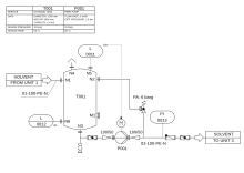
A piping and instrumentation diagram (P&ID or PID) is a detailed diagram in the process industry which shows the piping and process equipment together with the instrumentation and control devices. It is also called as mechanical flow diagram (MFD).[1]
Superordinate to the P&ID is the process flow diagram (PFD) which indicates the more general flow of plant processes and the relationship between major equipment of a plant facility.
Contents and function edit


A piping and instrumentation diagram (P&ID) is defined as follows:
- A diagram which shows the interconnection of process equipment and the instrumentation used to control the process. In the process industry, a standard set of symbols is used to prepare drawings of processes. The instrument symbols used in these drawings are generally based on International Society of Automation (ISA) Standard S5.1
- The primary schematic drawing used for laying out a process control installation.
They usually contain the following information:
- Mechanical equipment, including:
- Pressure vessels, columns, tanks, pumps, compressors, heat exchangers, furnaces, wellheads, fans, cooling towers, turbo-expanders, pig traps (see 'symbols' below)
- Bursting discs, restriction orifices, strainers and filters, steam traps, moisture traps, sight-glasses, silencers, flares and vents, flame arrestors, vortex breakers, eductors
- Process piping, sizes and identification, including:
- Pipe classes and piping line numbers
- Flow directions
- Interconnections references
- Permanent start-up, flush and bypass lines
- Pipelines and flowlines
- Blinds and spectacle blinds
- Insulation and heat tracing
- Process control instrumentation and designation (names, numbers, unique tag identifiers), including:
- Valves and their types and identifications (e.g. isolation, shutoff, relief and safety valves, valve interlocks)
- Control inputs and outputs (sensors and final elements, interlocks)
- Miscellaneous - vents, drains, flanges, special fittings, sampling lines, reducers and swages
- Interfaces for class changes
- Computer control system
- Identification of components and subsystems delivered by others
P&IDs are originally drawn up at the design stage from a combination of process flow sheet data, the mechanical process equipment design, and the instrumentation engineering design. During the design stage, the diagram also provides the basis for the development of system control schemes, allowing for further safety and operational investigations, such as a Hazard and operability study (HAZOP). To do this, it is critical to demonstrate the physical sequence of equipment and systems, as well as how these systems connect.
P&IDs also play a significant role in the maintenance and modification of the process after initial build. Modifications are red-penned onto the diagrams and are vital records of the current plant design.
They are also vital in enabling development of;
- Control and shutdown schemes
- Safety and regulatory requirements
- Start-up sequences
- Operational understanding.
P&IDs form the basis for the live mimic diagrams displayed on graphical user interfaces of large industrial control systems such as SCADA and distributed control systems.
Identification and reference designation edit
Based on STANDARD ANSI/ISA S5.1 and ISO 14617-6, the P&ID is used for the identification of measurements within the process. The identifications consist of up to 5 letters. The first identification letter is for the measured value, the second is a modifier, 3rd indicates passive/readout function, 4th - active/output function, and the 5th is the function modifier. This is followed by loop number, which is unique to that loop. For instance FIC045 means it is the Flow Indicating Controller in control loop 045. This is also known as the "tag" identifier of the field device, which is normally given to the location and function of the instrument. The same loop may have FT045 - which is the flow transmitter in the same loop.
| Letter | Column 1 (Measured value) |
Column 2 (Modifier) |
Column 3 (Readout/passive function) |
Column 4 (Output/active function) |
Column 5 (Function modifier) |
|---|---|---|---|---|---|
| A | Analysis | Alarm | |||
| B | Burner, combustion | User choice | User choice | User choice | |
| C | User's choice (usually conductivity) | Control | Close | ||
| D | User's choice (usually density) | Difference | Deviation | ||
| E | Voltage | Sensor | |||
| F | Flow rate | Ratio | |||
| G | User's choice (usually gaging/gauging) | Gas | Glass/gauge/viewing | ||
| H | Hand | High | |||
| I | Current | Indicate | |||
| J | Power | Scan | |||
| K | Time, time schedule | Time rate of change | Control station | ||
| L | Level | Light | Low | ||
| M | User's choice | Middle / intermediate | |||
| N | User's choice (usually torque) | User choice | User choice | User choice | |
| O | User's choice | Orifice | Open | ||
| P | Pressure | Point/test connection | |||
| Q | Quantity | Totalize/integrate | Totalize/integrate | ||
| R | Radiation | Record | Run | ||
| S | Speed, frequency | Safety (Non SIS (S5.1)) | Switch | Stop | |
| T | Temperature | Transmit | |||
| U | Multivariable | Multifunction | Multifunction | ||
| V | Vibration, mechanical analysis | Valve or damper | |||
| W | Weight, force | Well or probe | |||
| X | User's choice (usually on-off valve as XV) | X-axis | Accessory devices, unclassified | Unclassified | Unclassified |
| Y | Event, state, presence | Y-axis | Auxiliary devices | ||
| Z | Position, dimension | Z-axis or Safety Instrumented System | Actuator, driver or unclassified final control element |
For reference designation of any equipment in industrial systems the standard IEC 61346 (Industrial systems, installations and equipment and industrial products — Structuring principles and reference designations) can be applied. For the function Measurement the reference designator B is used, followed by the above listed letter for the measured variable.
For reference designation of any equipment in a power station the KKS Power Plant Classification System can be applied.
Symbols of chemical apparatus and equipment edit
Below are listed some symbols of chemical apparatus and equipment normally used in a P&ID, according to ISO 10628 and ISO 14617.
 |
Pipe |  |
Thermally insulated pipe |  |
Jacketed pipe |  |
Cooled or heated pipe |
 |
Flexible connection |  |
Hydraulic pump |  |
Pump |  |
Vacuum pump or compressor |
 |
Fan |  |
Axial fan |  |
Radial fan |  |
Dryer |
 |
Jacketed mixing vessel (autoclave) |  |
Half pipe mixing vessel |  |
Pressurized horizontal vessel |  |
Pressurized vertical vessel |
 |
Packed column |  |
Plate column |  |
Furnace |  |
Cooling tower |
 |
Heat exchanger |  |
Coil heat exchanger |  |
Cooler |  |
Plate & frame heat exchanger |
 |
Double pipe heat exchanger |  |
Fixed straight tubes heat exchanger |  |
U-shaped tubes heat exchanger |  |
Spiral heat exchanger |
 |
Covered gas vent |  |
Curved gas vent |  |
Air filter |  |
Funnel or tundish |
 |
Steam trap |  |
Viewing glass |  |
Pressure reducing valve |  |
Valve |
 |
Gate valve |  |
Control valve |  |
Manual valve |  |
Check valve |
 |
Needle valve |  |
Butterfly valve |  |
Diaphragm valve |  |
Ball valve |
 |
Check valve | |
Back draft damper |  |
Bag |  |
Gas bottle |

|
Globe valve | 
|
3-way valve | 
|
Piston or reciprocating compressor | 
|
Relief valve |
| Rupture disc | Turboexpander | Centrifugal pump | Reciprocating pump |
Historical use edit
Prior to the advent of computer-aided design (CAD) in the late 1980s, P&IDs were drawn by hand. The drawing template shown below, actual size 225.mm by 111 mm, is typical of those used to draw P&IDs.

Piping and instrumentation diagram manual drawing template (1980s). Symbol key:
- Vessel dished end
- Motor driven pump or compressor and baseplate
- Valves
- Valve diaphragm actuator
- Shell and tube heat exchanger
- Flexible hose, bellows
- Ejector
- Machine driven pump or other device
- Reducers
See also edit
External links edit
- Learn How to Read P&ID Drawings – A Complete Guide
- Interpreting Piping and Instrumentation Diagrams-Symbology
- Commons:Category:Chemical engineering symbols - A list of P&ID symbols in SVG format
References edit
- ^ Turton, Richard; Bailie, Richard C.; Whiting, Wallace B.; Shaeiwitz, Joseph A.; Bhattacharyya, Debangsu (2012). Analysis, synthesis, and design of chemical processes. Prentice Hall international series in the physical and chemical engineering sciences (4th ed.). Upper Saddle River, N.J. Munich: Prentice Hall. ISBN 978-0-13-261812-0.