


Summary
A priority encoder is a circuit or algorithm that compresses multiple binary inputs into a smaller number of outputs, similar to a simple encoder. The output of a priority encoder is the binary representation of the index of the most significant activated line. In contrast to the simple encoder, if two or more inputs to the priority encoder are active at the same time, the input having the highest priority will take precedence. It is an improvement on a simple encoder because it can handle all possible input combinations, but at the cost of extra logic.[1]
Applications of priority encoders include their use in interrupt controllers (to allow some interrupt requests to have higher priority than others), decimal or binary encoding, and analog-to-digital / digital to-analog conversion.[2]
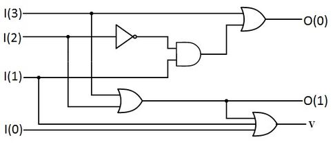
A truth table of a single bit 4-to-2 priority encoder is shown, where the inputs are shown in decreasing order of priority left-to-right, and "x" indicates a don't care term - i.e. any input value there yields the same output since it is superseded by a higher-priority input. The (usually-included[a]) "v" output indicates if the input is valid.
| Input | Output | |||||
| I3 | I2 | I1 | I0 | O1 | O0 | v |
| 0 | 0 | 0 | 0 | x | 0 | |
| 0 | 0 | 0 | 1 | 0 | 0 | 1 |
| 0 | 0 | 1 | x | 0 | 1 | 1 |
| 0 | 1 | x | 1 | 0 | 1 | |
| 1 | x | 1 | 1 | 1 | ||
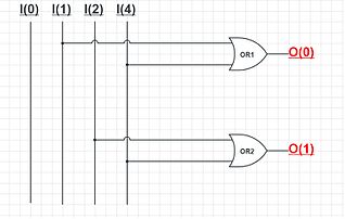
Priority encoders can be easily connected in arrays to make larger encoders, such as one 16-to-4 encoder made from six 4-to-2 priority encoders – four 4-to-2 encoders having the signal source connected to their inputs, and the two remaining encoders take the output of the first four as input.
Recursive construction of priority encoders[3][4][5] edit
A priority-encoder, also called leading zero detector (LZD) or leading zero counter (LZC), receives an -bit input vector and detects the index of the first binary ‘1’ in the input vector. A valid signal indicates if any binary ‘1’ was detected in the input vector, hence the index is valid.

Priority-encoders can be efficiently constructed by recursion. The input vector is split into equal fragments with bits. A priority encoder with a narrower width of 𝑛/𝑘 is applied for each fragment. The valid bit of each of the ‘s goes to a bit to detect the first valid fragment. The location of this fragment is the higher part of the overall index, and steers the exact location within the fragment itself to produce the lower part of the overall index.


The depth of the proposed structure is , while the hardware area complexity is . If Altera's Stratix V or equivalent device is used, is recommended to achieve higher performance and area compression, since the mux can be implemented using 6-LUT, hence an entire ALM.


An open-source Verilog generator for the recursive priority-encoder is available online.[6]

A behavioral description of priority encoder in Verilog is as follows.[6]
// behavioural description of priority enconder;
// https://github.com/AmeerAbdelhadi/Indirectly-Indexed-2D-Binary-Content-Addressable-Memory-BCAM

module pe_bhv
 #( parameter                   OHW = 512 ) // encoder one-hot input width
  ( input                       clk       , // clock for pipelined priority encoder
    input                       rst       , // registers reset for pipelined priority encoder
    input      [      OHW -1:0] oht       ,  // one-hot input  / [      OHW -1:0]
    output reg [`log2(OHW)-1:0] bin       ,  // first '1' index/ [`log2(OHW)-1:0]
    output reg                  vld       ); // binary is valid if one was found

  // use while loop for non fixed loop length
  // synthesizable well with Intel's QuartusII
  always @(*) begin
    bin = {`log2(OHW){1'b0}};
    vld = oht[bin]         ;
    while ((!vld) && (bin!=(OHW-1))) begin
      bin = bin + 1 ;
      vld = oht[bin];
    end
  end

endmodule
Simple encoder edit
A simple encoder circuit is a one-hot to binary converter. That is, if there are 2n input lines, and at most only one of them will ever be high, the binary code of this 'hot' line is produced on the n-bit output lines.
Notes edit
References edit
- ^ Mano, Moshe Morris; Ciletti, Michael D. (2007). Digital Design (Fourth ed.). Upper Saddle River, NJ: Pearson Prentice Hall. p. 156. ISBN 978-0-13-198924-5.
- ^ The TTL Applications Handbook. Fairchild Semiconductor. August 1973. p. 4-4.
- ^ Abdelhadi, Ameer M. S. (2016). Architecture of block-RAM-based massively parallel memory structures : multi-ported memories and content-addressable memories (Thesis). University of British Columbia.
- ^ Abdelhadi, Ameer M.S.; Lemieux, Guy G.F. (May 2015). "Modular SRAM-Based Binary Content-Addressable Memories". 2015 IEEE 23rd Annual International Symposium on Field-Programmable Custom Computing Machines. pp. 207–214. doi:10.1109/FCCM.2015.69. ISBN 978-1-4799-9969-9. S2CID 16985129.
- ^ Abdelhadi, Ameer M. S.; Lemieux, Guy G. F. (December 2014). "Deep and narrow binary content-addressable memories using FPGA-based BRAMs". 2014 International Conference on Field-Programmable Technology (FPT). pp. 318–321. doi:10.1109/FPT.2014.7082808. ISBN 978-1-4799-6245-7. S2CID 2074456.
- ^ a b Abdelhadi, A.M.S.; Lemieux, G.G.F. (2014). "Modular SRAM-based Indirectly-indexed 2D Binary Content Addressable Memory II2DCAM". The University of British Columbia.
Abdelhadi, A.M.S.; Lemieux, G.G.F. (2015). "Modular SRAM-Based Binary Content-Addressable Memories" (PDF). 2015 IEEE 23rd Annual International Symposium on Field-Programmable Custom Computing Machines. IEEE. pp. 207–214. doi:10.1109/FCCM.2015.69. ISBN 978-1-4799-9969-9. S2CID 16985129.