


Summary
Radio receiver design includes the electronic design of different components of a radio receiver which processes the radio frequency signal from an antenna in order to produce usable information such as audio. The complexity of a modern receiver and the possible range of circuitry and methods employed are more generally covered in electronics and communications engineering. The term radio receiver is understood in this article to mean any device which is intended to receive a radio signal in order to generate useful information from the signal, most notably a recreation of the so-called baseband signal (such as audio) which modulated the radio signal at the time of transmission in a communications or broadcast system.
Fundamental considerations edit
Design of a radio receiver must consider several fundamental criteria to produce a practical result. The main criteria are gain, selectivity, sensitivity, and stability. The receiver must contain a detector to recover the information initially impressed on the radio carrier signal, a process called modulation.[1]
Gain is required because the signal intercepted by an antenna will have a very low power level, on the order of picowatts or femtowatts. To produce an audible signal in a pair of headphones requires this signal to be amplified a trillion-fold or more. The magnitudes of the required gain are so great that the logarithmic unit decibel is preferred - a gain of 1 trillion times the power is 120 decibels, which is a value achieved by many common receivers. Gain is provided by one or more amplifier stages in a receiver design; some of the gain is applied at the radio-frequency part of the system, and the rest at the frequencies used by the recovered information (audio, video, or data signals).
Selectivity is the ability to "tune in" to just one station of the many that may be transmitting at any given time. An adjustable bandpass filter is a typical stage of a receiver. A receiver may include several stages of bandpass filters to provide sufficient selectivity. Additionally, the receiver design must provide immunity from spurious signals that may be generated within the receiver that would interfere with the desired signal. Broadcasting transmitters in any given area are assigned frequencies so that receivers can properly select the desired transmission; this is a key factor limiting the number of transmitting stations that can operate in a given area.
Sensitivity is the ability to recover the signal from the background noise. Noise is generated in the path between transmitter and receiver, but is also significantly generated in the receiver's own circuits. Inherently, any circuit above absolute zero generates some random noise that adds to the desired signals. In some cases, atmospheric noise is far greater than that produced in the receiver's own circuits, but in some designs, measures such as cryogenic cooling are applied to some stages of the receiver, to prevent signals from being obscured by thermal noise. A very good receiver design may have a noise figure of only a few times the theoretical minimum for the operating temperature and desired signal bandwidth. The objective is to produce a signal-to-noise ratio of the recovered signal sufficient for the intended purpose. This ratio is also often expressed in decibels. A signal-to-noise ratio of 10 dB (signal 10 times as powerful as noise) might be usable for voice communications by experienced operators, but a receiver intended for high-fidelity music reproduction might require 50 dB or higher signal-to-noise ratio.
Stability is required in at least two senses. Frequency stability; the receiver must stay "tuned" to the incoming radio signal and must not "drift" with time or temperature. Additionally, the great magnitude of gain generated must be carefully controlled so that spurious emissions are not produced within the receiver. These would lead to distortion of the recovered information, or, at worst, may radiate signals that interfere with other receivers.
The detector stage recovers the information from the radio-frequency signal, and produces the sound, video, or data that was impressed on the carrier wave initially. Detectors may be as simple as an "envelope" detector for amplitude modulation, or may be more complex circuits for more recently developed techniques such as frequency-hopping spread spectrum.
While not fundamental to a receiver, automatic gain control is a great convenience to the user, since it automatically compensates for changing received signal levels or different levels produced by different transmitters.
Many different approaches and fundamental receiver "block diagrams" have developed to address these several, sometimes contradictory, factors. Once these technical objectives have been achieved, the remaining design process is still complicated by considerations of economics, patent rights, and even fashion.
Crystal radio edit
A crystal radio uses no active parts: it is powered only by the radio signal itself, whose detected power feeds headphones in order to be audible at all. In order to achieve even a minimal sensitivity, a crystal radio is limited to low frequencies using a large antenna (usually a long wire). It relies on detection using some sort of semiconductor diode such as the original cat's-whisker diode discovered long before the development of modern semiconductors.
A crystal receiver is very simple and can be easy to make or even improvise, for example, the foxhole radio. However, the crystal radio needs a strong RF signal and a long antenna to operate. It displays poor selectivity since it only has one tuned circuit.
Tuned radio frequency edit
The tuned radio frequency receiver (TRF) consists of a radio frequency amplifier having one or more stages all tuned to the desired reception frequency. This is followed by a detector, typically an envelope detector using a diode, followed by audio amplification. This was developed after the invention of the triode vacuum tube, greatly improving the reception of radio signals using electronic amplification which had not previously been available. The greatly improved selectivity of the superheterodyne receiver overtook the TRF design in almost all applications, however the TRF design was still used as late as the 1960s among the cheaper "transistor radios" of that era.
Reflex edit
The reflex receiver was a design from the early 20th century which consists of a single-stage TRF receiver but which used the same amplifying tube to also amplify the audio signal after it had been detected. This was in an era where each tube was a major cost (and consumer of electrical power) so that a substantial increase in the number of passive elements would be seen as preferable to including an additional tube. The design tends to be rather unstable, and is obsolete.
Regenerative edit

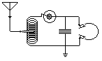
The regenerative receiver also had its heyday at the time where adding an active element (vacuum tube) was considered costly. In order to increase the gain of the receiver, positive feedback was used in its single RF amplifier stage; this also increased the selectivity of the receiver well beyond what would be expected from a single tuned circuit. The amount of feedback was quite critical in determining the resulting gain and had to be carefully adjusted by the radio operator. Increasing the feedback beyond a point caused the stage to oscillate at the frequency it was tuned to.
Self-oscillation reduced the quality of its reception of an AM (voice) radio signal but made it useful as a CW (Morse code) receiver. The beat signal between the oscillation and the radio signal would produce an audio "beeping" sound. The oscillation of the regenerative receiver could also be a source of local interference. An improved design known as the super-regenerative receiver improved the performance by allowing an oscillation to build up which was then "quenched", with that cycle repeating at a rapid (ultrasonic) rate. From the accompanying schematic for a practical regenerative receiver, one can appreciate its simplicity in relation to a multi-stage TRF receiver, while able to achieve the same level of amplification through the use of positive feedback.
Direct conversion edit
In the Direct conversion receiver, the signals from the antenna are only tuned by a single tuned circuit before entering a mixer where they are mixed with a signal from a local oscillator which is tuned to the carrier wave frequency of the transmitted signal. This is unlike the superheterodyne design, where the local oscillator is at an offset frequency. The output of this mixer is thus audio frequency, which is passed through a low pass filter into an audio amplifier which may drive a speaker.
For receiving CW (morse code) the local oscillator is tuned to a frequency slightly different from that of the transmitter in order to turn the received signal into an audible "beep."
- Advantages
- Simpler than a superheterodyne receiver
- Disadvantages
- Poor rejection of strong signals at adjacent frequencies compared to a superheterodyne receiver.
- Increased noise or interference when receiving a SSB signal since there is no selectivity against the undesired sideband.
Superheterodyne edit
Practically all modern receivers are of the superheterodyne design. The RF signal from the antenna may have one stage of amplification to improve the receiver's noise figure, although at lower frequencies this is typically omitted. The RF signal enters a mixer, along with the output of the local oscillator, in order to produce a so-called intermediate frequency (IF) signal. An early optimization of the superheterodyne was to combine the local oscillator and mixer into a single stage called "converter". The local oscillator is tuned to a frequency somewhat higher (or lower) than the intended reception frequency so that the IF signal will be at a particular frequency where it is further amplified in a narrow-band multistage amplifier. Tuning the receiver involves changing the frequency of the local oscillator, with further processing of the signal (especially in relation to increasing the receiver) conveniently done at a single frequency (the IF frequency) thus requiring no further tuning for different stations.

Here we show block diagrams for typical superheterodyne receivers for AM and FM broadcast respectively. This particular FM design uses a modern phase locked loop detector, unlike the frequency discriminator or ratio detector used in earlier FM receivers.
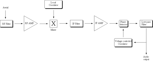
For single conversion superheterodyne AM receivers designed for medium wave (AM broadcast) the IF is commonly 455 kHz. Most superheterodyne receivers designed for broadcast FM (88 - 108 MHz) use an IF of 10.7 MHz. TV receivers often use intermediate frequencies of about 40 MHz. Some modern multiband receivers actually convert lower frequency bands first to a much higher frequency (VHF) after which a second mixer with a tunable local oscillator and a second IF stage process the signal as above.
Software-defined radio edit
Software-defined radio (SDR) is a radio communication system where components, that have been traditionally implemented in hardware (e.g. mixers, filters, amplifiers, modulators/demodulators, detectors, etc.) are instead implemented by means of software on a personal computer or embedded system.[2] While the concept of SDR is not new, the rapidly evolving capabilities of digital electronics render practical many processes which used to be only theoretically possible.
See also edit
Further reading edit
- Books
- Radiocommunication handbook (RSGB), ISBN 0-900612-58-4
- Patents
- U.S. patent 1,748,435 Crystal Radio Apparatus. H. Adams
Notes and references edit
- ^ Wes Hayward, Doug De Maw (ed),Solid State Design for the Radio Amateur, Chapter 5 "Receiver Design Basics", American Radio Relay League 1977, no ISBN
- ^ Software Defined Radio: Architectures, Systems and Functions (Markus Dillinger, Kambiz Madani, Nancy Alonistioti) Page xxxiii (Wiley & Sons, 2003, ISBN 0-470-85164-3)