


Summary
Reinforced rubber products are one of the largest groups of composite materials, though rarely referred to as composite materials. Familiar examples are automobile tyres, hoses, and conveyor belts.

Composite reinforced structure edit
Reinforced rubber products combine a rubber matrix and a reinforcing material so that high strength to flexibility ratios can be achieved. The reinforcing material, usually a kind of fibre, provides the strength and stiffness. The rubber matrix, with low strength and stiffness, provides air-fluid tightness and supports the reinforcing materials to maintain their relative positions. These positions are of great importance because they influence the resulting mechanical properties.
A composite structure in which all fibres are loaded equally everywhere when pressurized, is called an isotropic structure, and the type of loading is named an isotensoidal loading. To meet the isotensoidal concept the structure geometry must have an isotensoid meridian profile and the fibres must be positioned following geodesic paths. A geodesic path connects two arbitrary points on a continuous surface by means of the shortest possible way.
Straight rubber hoses edit

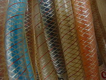
To achieve optimal loading in a straight rubber hose the fibres must be positioned under an angle of approximately 54.7 angular degrees, also referred to as the magic angle. The magic angle of 54.7 exactly balances the internal-pressure-induced longitudinal stress and the hoop (circumferential) stress, as observed in most biological pressurized fiber-wound cylinders, like arteries. If the fiber angle is initially above or below 54.7, it will change under increased internal pressure until it rises to the magic angle where hoop stresses and longitudinal stresses equalize, with concomitant accommodations in hose diameter and hose length. A hose with an initially low fiber angle will rise under pressure to 54.7, inducing a hose diameter increase and a length decrease, whereas a hose with an initially high fiber angle will drop to 54.7, inducing a hose diameter decrease and a length increase. The equilibrium state is a fiber angle of 54.7. In this situation, the fibres tend to be loaded purely in tension, so ~100% of their strength resists the forces acting on the hose due to the internal pressure. (The magic angle for cylindrical shapes of 54.7 angular degrees is based on calculations in which the influence of the matrix material is neglected. Therefore, depending on the stiffness of the rubber material used, the actual equilibrium angle can vary a few tenths of degrees from the magic angle.)[citation needed]
When the fibres of the reinforcement structure are placed under angles larger than 54.7 angular degrees, the fibres want to relocate to their optimal path when pressurized. This means that the fibres will re-orient themselves until they have reached their force equilibrium. In this case this will lead to an increase in length and a decrease in diameter. With angles smaller than 54.7 degrees the opposite will occur. A product which makes use of this principle is a pneumatic muscle.
Reinforcement of complex shaped rubber products edit

For a cylinder with a constant diameter, the reinforcement angle is constant as well and is 54.7º. This also known as the magic angle or neutral angle. The neutral angle is the angle where a wound structure is in equilibrium. For a cylinder, this is 54.7º, but for a more complex shape like a bellows which has a varying radius over the length of the product, this neutral angle is different for each radius. In other words, for complex shapes there is not one magic angle but the fibres follow a geodesic path with angles varying with the change in radius. To obtain a reinforcement structure with isotensoidal loading the geometry of the complex shape must follow an isotensoid meridian profile.
Reinforcement application technology edit
The mil fabric reinforcement can be applied on the rubber products with different processes. For straight hoses, the most used processes are braiding, spiralling, knitting, and wrapping. The first three processes have in common that multiple strands of fibres are applied to the product simultaneously on a predetermined pattern in an automated process. The fourth process comprises manual or semi-automated wrapping of rubber sheets reinforced with fabric plies. For the reinforcement of complex shaped rubber products like bellows most manufacturers use these fabric reinforced rubber sheets. These sheets are made by calendering of rubber onto pre-woven fabric plies. The products are manufactured by wrapping (mostly manually) these sheets around a mandrel until enough rubber and reinforcement is applied. However, the disadvantage of using these sheets is that it is impossible to control the positioning of the individual fibres of the fabric when applied on complex shapes. Therefore, no geodesic paths can be achieved and therefore also no isotensoid loading is possible. To obtain isotensoide loading on a complex shape, the shape must have an isotensoideal profile and geodesic positioning of the fibre structure is required. This can be achieved by using automated winding processes like filament winding or spiralling.
References edit
- Koussios, S.; Nooij, S. M.; Beukers, A. "Pressurised structures & hoses: improved structural performance and flexibility through optimal fibre reinforcement" (PDF). Faculty of Aerospace Engineering, Delft University of Technology.