


Summary
A Scott-T transformer or Scott connection is a type of circuit used to produce two-phase electric power (2 φ, 90 degree phase rotation)[1] from a three-phase (3 φ, 120 degree phase rotation) source, or vice versa. The Scott connection evenly distributes a balanced load between the phases of the source. The Scott three-phase transformer was invented by Westinghouse engineer Charles F. Scott in the late 1890s to bypass Thomas Edison's more expensive rotary converter and thereby permit two-phase generator plants to drive three-phase motors.[2]
Interconnection edit
At the time of the invention, two-phase motor loads also existed and the Scott connection allowed connecting them to newer three-phase supplies with the currents equal on the three phases.[3] This was valuable for getting equal voltage drop and thus feasible regulation of the voltage from the electric generator (the phases cannot be varied separately in a three-phase machine). Nikola Tesla's original polyphase power system was based on simple-to-build two-phase four-wire components. However, as transmission distances increased, the more transmission-line efficient three-phase system became more common. (Three phase power can be transmitted with only three wires, where the two-phase power systems required four wires, two per phase.) Both 2 φ and 3 φ components coexisted for a number of years and the Scott-T transformer connection allowed them to be interconnected.
Technical details edit
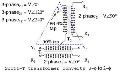
Assuming the desired voltage is the same on the two and three phase sides, the Scott-T transformer connection (shown right) consists of a centre-tapped 1:1 ratio main transformer, T1, and a √3/2(≈86.6%) ratio teaser transformer, T2. The centre-tapped side of T1 is connected between two of the phases on the three-phase side. Its centre tap then connects to one end of the lower turn count side of T2, the other end connects to the remaining phase. The other side of the transformers then connect directly to the two pairs of a two-phase four-wire system.
Unbalanced loads edit
Two-phase motors draw constant power, just as three-phase motors do, so a balanced two-phase load is converted to a balanced three-phase load. However if a two-phase load is not balanced (more power drawn from one phase than the other), no arrangement of transformers (including the Scott-T transformers) can restore balance: Unbalanced current on the two-phase side causes unbalanced current on the three-phase side. Since the typical two-phase load was a motor, the current in the two phases was presumed inherently equal during the Scott-T development.
In modern times people have tried to revive the Scott connection as a way to power single-phase electric railways from three-phase Utility supplies. This will not result in balanced current on the three-phase of being equal. The instantaneous difference in loading on the two sections will be seen as an imbalance in the three-phase supply; there is no way to smooth it out with transformers.[4]
Back to back arrangement edit

The Scott-T transformer connection may also be used in a back-to-back T-to-T arrangement for a three-phase to three-phase connection. This is a cost-saving in the lower-power transformers due to the two-coil T connected to a secondary two-coil T instead of the traditional three-coil primary to three-coil secondary transformer. In this arrangement the X0 neutral tap is part way up on the secondary teaser transformer (see right). The voltage stability of this T-to-T arrangement as compared to the traditional three-coil primary to three-coil secondary transformer is questioned, as the "per unit" impedance of the two windings (primary and secondary, respectively) are not the same in a T-to-T configuration, whereas the three windings (primary and secondary, respectively) are the same in a three transformer configuration, if the three transformers are identical.
Three-phase to three-phase (also called "T-connected") distribution transformers are seeing increasing applications. The primary must be delta-connected (Δ), but the secondary may be either delta or "wye"-connected (Y), at the customer's option, with X0 providing the neutral for the "wye" case. Taps for either case are usually provided. The customary maximum capacity of such a distribution transformer is 333 kVA (a third of a megawatt at unity power factor).[citation needed]
See also edit
References edit
- ^ Distribution Transformer Manual, GET-2485T. Hickory, NC: General Electric Company. 1996. p. 64.
- ^ Passer, Harold C. (1953). The Electrical Manufacturers, 1875-1900. Harvard. p. 315.
- ^ "All About Circuits". Retrieved 2014-08-04.
- ^ General Electric (Jan 1957). "(unknown)". AIEE Transactions: 432–445.
{{cite journal}}: Cite uses generic title (help) The cited article is a GE paper which points out that railway unbalance, even via Scott-T transformers, affects generators, the motors of other customers and presumably delta connected transformers. Even small unbalances can cause heating. However, because electric systems have grown larger over the 20th century, the paper suggests that the railways are now a tolerable load, provided one has a confirming system analysis. Scott-T transformers may not even be relevant, since direct line-to-line load connections may be sufficient. So this leaves a potential solution, but the single-phase load should then be viewed as being tolerated, not balanced. Allowing it also raises the question: "What if other customers asked for the same toleration?"