


Summary
The South African Railways Class 25 4-8-4 of 1953 was a condensing steam locomotive.
| South African Class 25 4-8-4 | |||||||||||||||||||||||||||||||||||||||||||||||||||||||||||||||||||||||||||||||||||||||||||||||||||||||||||||||||||||||||||||||||||||
|---|---|---|---|---|---|---|---|---|---|---|---|---|---|---|---|---|---|---|---|---|---|---|---|---|---|---|---|---|---|---|---|---|---|---|---|---|---|---|---|---|---|---|---|---|---|---|---|---|---|---|---|---|---|---|---|---|---|---|---|---|---|---|---|---|---|---|---|---|---|---|---|---|---|---|---|---|---|---|---|---|---|---|---|---|---|---|---|---|---|---|---|---|---|---|---|---|---|---|---|---|---|---|---|---|---|---|---|---|---|---|---|---|---|---|---|---|---|---|---|---|---|---|---|---|---|---|---|---|---|---|---|---|---|
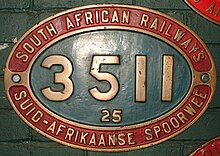
 3511 at Hartswater, 24 April 1981 | |||||||||||||||||||||||||||||||||||||||||||||||||||||||||||||||||||||||||||||||||||||||||||||||||||||||||||||||||||||||||||||||||||||
| |||||||||||||||||||||||||||||||||||||||||||||||||||||||||||||||||||||||||||||||||||||||||||||||||||||||||||||||||||||||||||||||||||||
| |||||||||||||||||||||||||||||||||||||||||||||||||||||||||||||||||||||||||||||||||||||||||||||||||||||||||||||||||||||||||||||||||||||
| |||||||||||||||||||||||||||||||||||||||||||||||||||||||||||||||||||||||||||||||||||||||||||||||||||||||||||||||||||||||||||||||||||||
| |||||||||||||||||||||||||||||||||||||||||||||||||||||||||||||||||||||||||||||||||||||||||||||||||||||||||||||||||||||||||||||||||||||
Between 1953 and 1955, the South African Railways placed ninety Class 25 condensing steam locomotives with a 4-8-4 Northern type wheel arrangement in service. The Class 25NC which was placed in service at the same time was a non-condensing version of the Class 25 condenser.[1][2]
Background edit
Owing to the difficulties experienced to obtain adequate supplies of suitable water in arid regions like the Great Karoo between Touws River and Kimberley and from De Aar into South West Africa (SWA), the South African Railways (SAR) began to give serious consideration to the possibility of introducing condensing locomotives as far back as the late 1930s. At one time it was considered to convert Class 12A 4-8-2 locomotives to condensing engines, but the idea was not put into practice.[1]
Condensing locomotives were a rarity, but no novelty to South Africa, since the first condensing steam locomotives had already entered service in the Cape of Good Hope in the late nineteenth century. Between 1886 and 1888, three well-tank condensing locomotives with a 0-4-0 wheel arrangement were placed in service by the Cape Copper Mining Company on its Namaqualand Railway, a 2 ft 6 in (762 mm) gauge line between Port Nolloth and O'okiep.[3]

On the SAR, it was only after World War II, that extensive condensing tests were carried out with the modified Class 20 locomotive. The approximately 90% water and 10% coal savings which were achieved during the tests with the Class 20 in the Eastern Transvaal and the Karoo in 1950 and 1951 led to the decision to proceed with the design of a new condensing locomotive.[1]
The result, the Class 25 4-8-4 Northern type condensing locomotive, can be considered as the ultimate in SAR non-articulated steam locomotive design. It was designed under the direction of L.C. Grubb, Chief Mechanical Engineer of the SAR from 1949 to 1954.[1]
Manufacturers edit


The design work on the locomotive's condensing apparatus and the condensing tender was carried out by Henschel & Son, who built one locomotive complete with tender, Number 3451, with works number 28730. After being tried in Kassel, it was then dispatched to the North British Locomotive Company (NBL) in Glasgow who built the rest of the Class 25 locomotives, numbered in the range from 3452 to 3540.[4] They were delivered between 1953 and 1955.[1][5][6][7][8]


Apart from the complete engine and tender of Number 3451, Henschel built sixty more of the condensing tenders to which they held the patent, with works numbers in the range from 28780 to 28839, as well as four spare boilers for the Classes 25 and 25NC with works numbers in the range from 28770 to 28773. The last 29 condensing tenders were built by NBL.[5][9][10]
In 1963, one more condensing tender, no. 3541, was built by the Salt River shops of the SAR on a spare cast frame which had been delivered as part of the original order which called for three spare frames, one for an engine and one each for a condenser and non-condenser tender.[9][11]
Characteristics edit
The boiler was similar to the Watson Standard no. 3B boiler of the Class 15F, but with the distance between tube plates reduced from 22 feet 6 inches (6,858 millimetres) to 19 feet (5,791 millimetres) by the addition of a combustion chamber. While this resulted in a slight decrease in the total evaporative heating surface, there was a 40% increase in the firebox heating surface and a better ratio of firebox to grate area. The boiler was lagged with Cape Asbestos mattresses, manufactured and fitted in South Africa.[6][12]
On the condensing locomotive, spent steam was recycled and condensed back to water for repeated use. Since the steam wasn't expelled up the chimney, the Class 25's smokebox contained a steam turbine-driven fan beneath the chimney to keep the draft going, with deflector plates that were supposed to prevent char from causing excessive wear on the fan blades.[1][6][13]

The smokebox of the Class 25 was similar to that of the Class 25NC, but with the front extended to accommodate the centrifugal blower which was driven by an exhaust steam turbine mounted under the front of the smokebox. Apart from the usual round smokebox door in the centre of the smokebox front plate, the complete front smokebox plate on both classes was hinged to the wrapper plate on the right hand side of the smokebox in addition to being bolted to the angle ring at the smokebox front, to facilitate less cramped access to the blower equipment, superheater header and tubes.[12]

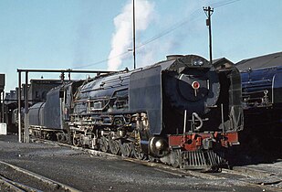
The draft turbine gave the locomotive its characteristic whining sound while running. As delivered, the Class 25 had the usual round smokebox front, but this was later modified by adding a banjo-shaped extension to also cover the exhaust steam turbine. Spent steam was fed through a thick pipe on the engine's left hand side back to the condensing tender.[1][5]
The banjo-shaped extension modification to the front of the smokebox was found necessary to cope with the copious amounts of char generated by brittle Witbank coal and mechanical stoking, since the original Henschel design proved to have too little capacity to keep accumulated char away from the exhaust turbine. Most of the char was collected in the trough of the banjo at the bottom of the smokebox front from where it was periodically ejected through a vertical steam ejector pipe inside the banjo door which exhausted immediately in front of the chimney.[1][6][13]
In service, the turbine-induced draft of the Class 25 actually performed better than the regular draft of the Class 25NC. One advantage of the condenser was that while getting up steam, the blower could be opened at a boiler pressure of about 15 to 20 pounds per square inch (103 to 138 kilopascals) to start the fan spinning, which drew the fire and accelerated getting up steam pressure. On a non-condensing locomotive the blower would be weak while steam pressure was still that low.[14]
Timken roller bearings, from Canton, Ohio, USA were used throughout, including on the three-axle tender bogies, the coupling and connecting rods as well as the crosshead gudgeon pins, while the locomotive's leading bogies and coupled wheels had Cannon-type axle boxes. Compared to earlier SAR practice, a novelty was the adoption of mechanical lubrication. A sixteen-feed lubricator was driven off the reversing link trunion. Since the Class 25 was entirely mounted on roller bearings, very little effort was required to move these huge locomotives.[1][6][12]
The cylinders and frames were cast in one piece while the steel cylinders and steam chests were fitted with cast iron liners. The tender frame was also a one-piece steel casting. The Alligator type crossheads were split on the vertical centre line and clamped on to the end of the piston rods, which had three coned rings engaging in grooves in the crossheads. The original coupling rods differed from the usual in the provision of three independent rods, thereby doing away with four knuckle joints and pins.[1][6]
The locomotive was able to negotiate curves with a radius of 275 feet (84 metres), with 1⁄4 inch (6 millimetres) gauge widening and 4+1⁄2 inches (114 millimetres) superelevation. The wheels, axles and axle boxes of the leading bogie were designed to be interchangeable with those of the Class 15F, while the wheels and axles of the trailing bogie were interchangeable with those of the Class 24's trailing bogie.[12]
The locomotive's brakes were operated by two 24 inches (610 millimetres) diameter cylinders on the engine and four 21 inches (533 millimetres) diameter cylinders on the tender. The brake rigging on the tender bogies were independent of each other and the front tender bogie was equipped with a hand brake. The engine and tender brake pipelines were fitted with delaying valves which delayed brake application on the locomotive until a predetermined degree of braking had been established throughout the train. A separate driver's brake valve permitted the continued application of locomotive brakes while the train brakes were being released or vacuum was being built up.[12]

Almost one third of the total length of the Type CZ condensing tender was taken up by the coal bunker, which included the oil separator equipment to remove oil from spent steam and the mechanical stoker equipment which had a maximum delivery rate of 12,000 pounds (5,443 kilograms) of coal per hour. The rear two-thirds was taken up by eight large radiators on each side, cooled by five steam-driven roof-mounted fans. The 5,000 imperial gallons (22,700 litres) water capacity consisted of two tanks, a 4,400 imperial gallons (20,000 litres) fresh water tank in the centre of the tender between the radiators and a 600 imperial gallons (2,730 litres) condensate tank under the tender belly between the bogies. Feedwater was taken directly from the condensate tank's hot contents rather than from the main tank's cold contents.[1][2][6][12]
Since the temperature of the condensed feedwater was too high for the use of ordinary injectors, the boiler was fed by two turbo-pumps located under the cab. Each pump had a capacity of approximately 88 imperial gallons (400 litres) per minute.[6][12]
The system proved to be extremely efficient and reduced water consumption by as much as 90% by using the same water up to eight times over, giving the Class 25 locomotive a range of 800 kilometres (500 miles) between water refills. In addition, the hot condensate feedwater resulted in a 7% reduction in coal consumption.[11][13][15][16]


The condensing tenders were rather appropriately classified as Type CZ, since CZ is also the motor vehicle registration letters of Beaufort West, the capital town of the Karoo where the Class 25 was to serve. Since spent steam was not expelled through the chimney, the condensers sounded unlike any other steam locomotive on South African rails. Their non-condensing and free exhausting Class 25NC sister locomotives had the usual sharp bark of a steam locomotive, especially under load, while the condensing Class 25 had more of a hoarse hollow chuff sound in addition to its turbine whine.[1][2]
Teething troubles edit
Soon after being placed in service, problems were experienced with failing connecting rods, big end bearings breaking up as well as cracks developing in the motion girder of the Alligator crossheads. After investigations by SAR engineers with assistance from South Africa's Council for Scientific and Industrial Research (CSIR), the crossheads, slide bars and coupling rods were modified. The crossheads were converted to the multiple-bearing type with single guide bars, a more sophisticated method of filtering out the cylinder and valve lubricant from the exhaust steam replaced the original centrifuge while the three independent coupling rods were replaced with the more conventional single coupling rod with knuckle joints.[1][13][17]
When new, the tapered Timken crankpin roller bearings soon became notorious for throwing their lubricant onto the underside of the boiler, from where it ran down to the lowest point and dripped onto the coupled wheel tyres along the way. This manufacturer's fault also applied to the Class 25NC and was one of the reasons for the reputation of both classes of being slippery. Timken managed to resolve the problem before all their bearings had been replaced, but by then about two-thirds of the locomotives had already been fitted with redesigned coupling rods with SKF crankpin ball bearings.[13]
Considerable trouble was also experienced with the induced draught equipment. The blower blades suffered heavy edge wear from solid particles in the exhaust and blade fractures occurred in both the blower and steam turbine wheels which called for intense investigation by SAR engineers, Henschel representatives and the CSIR.[1][17]
An initial attempt to solve the blade fracture problem by increasing the breadth of the blade roots from 7 to 14 millimetres (0.28 to 0.55 inches) was unsuccessful. Fatigue tests and stress analysis by the CSIR showed that both sizes of blades failed due to fatigue at the sharp fillets as a result of the repeated changes in the centrifugal load due to variations in the turbine rotational speed. The solution was arrived at when it was realised that none of the single "lock" blades, which were supported by two conical pins, of any rotor had ever failed. When such conical pins were also introduced between all the other blades in the rotors, fatigue tests showed that this made them considerably stronger. Some time later it was found that welding the blades onto the rotor edge proved to be a good cheaper alternative. The design was eventually amended with the redesigned exhaust fan being manufactured from manganese steel and the problem was solved.[13][18]
Service edit
The Class 25 was built specifically for work in the Karoo and the Kalahari, where water is a scarce resource. They initially served on the unelectrified mainline from Touws River via Beaufort West to De Aar where they handled all goods and passenger traffic, including top-line passenger trains like the Blue Train. When the section from Touws River to Beaufort West was electrified, the Class 25 continued working between Beaufort West and De Aar, but it now also worked between De Aar and Kimberley, across from Kimberley to Bloemfontein to the east as well as westward from Kimberley to Postmasburg, Sishen and Hotazel in the Kalahari. From Postmasburg they worked iron and manganese ore to Bloemfontein, where relays of Free State power took over to Harrismith.[11][16][19]
Rebuilding edit
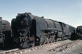
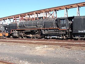
The Class 25 was a complex locomotive which required high maintenance, especially on the turbine blower fans in the smokebox, the blades of which needed to be replaced frequently due to damage by solid particles in the exhaust. The equally complex condensing tender also needed frequent maintenance. Between 1973 and 1980, after serving for twenty years, and partially accelerated by the introduction of electric and diesel-electric traction over routes which were previously served exclusively by the Class 25, all but three of the condensing locomotives, numbers 3451, 3511 and 3540, were converted to free exhausting and non-condensing locomotives as they went through the workshops for major overhauls. The converted locomotives were reclassified to Class 25NC.[13][20]
It has been suggested that, had the Class 25 been modified to produce less black smoke or char as a result of incomplete combustion, in accordance with the Gas Producer Combustion System (GPCS) principles, which were applied by mechanical engineer David Wardale when he rebuilt a Class 25NC locomotive to the Class 26 Red Devil, the problem of char damage to the fan blades could have been largely eliminated. The GPCS program, however, only began near the end of the conversion of the Class 25s.[11][21][22]

The first conversion was done at De Aar on no. 3452, and consisted of the turbine and exhaust pipe being removed from the smokebox and replaced with a blastpipe and chimney. The tender was stripped of its condensing equipment, but retained its original fresh water and condensate tanks and feed pumps, with the radiator framing and roof panelled over. The locomotive's general appearance therefore changed little, but while the conversion of no. 3452 was aesthetically superior when compared with subsequent conversions, it did not carry enough water.[23]

The rest of the fleet was rebuilt at the Salt River shops in Cape Town. In the process, their condensing tenders were also rebuilt to ordinary coal-and-water tenders, by removing the condensing radiators and roof fans, and replacing them with a massive round-topped water tank.[20]

The shape and appearance of the tender conversion was dictated by strength considerations. Shortening the tender frame was considered, but it was eventually retained as it was. To replicate the Class 25NC tender tank and bunker on the longer Type CZ tender frame would have exceeded the permissible axle loading by a considerable amount. The long cast-steel frame of the tender was very flexible, but the radiator framing and roof contributed a great deal to the vertical stiffness. The final form of the rebuilt tender's tank supplied enough strength, with its semi-circular top welded to the original fresh water tank via the fan supports and the long triangular gussets set into the bunker sides which extended past the midpoint of the frame. Locomotives with rebuilt tenders were soon nicknamed Worshond, Afrikaans for dachshund and literally translated as sausage dog. The worshond tenders were reclassified as Type EW2.[9][20][23]

When the Class 25 condensers were converted to Class 25NC non-condensers, their number plates were copied and recast with the additional "NC" for "non-condensing" squeezed in next to the existing "25", which resulted in a lopsided class indication on their plates. Locomotives with all four characters neatly in line and centred were therefore usually identifiable as original Class 25NCs. After they were relieved of their condensing gear, these locomotives served for another eleven years, before being withdrawn from service by the SAR when steam was completely replaced by electric and diesel-electric traction.[11][16][24]
Preservation edit
The following 25 class have survived. Both are still owned by the Transnet Heritage Foundation. Neither are operational.
| Number | Works No. | Transnet Heritage Foundation / Private | Leaselend / Owner | Current Location | Notes |
|---|---|---|---|---|---|
| 3451 | Hensc 28730 | Transnet Heritage Foundation | Steamnet 2000 | Germiston Locomotive Depot | |
| 3511 | NBL 27371 | Transnet Heritage Foundation | Steamnet 2000 | Kimberley Locomotive Depot |
Works numbers edit
The locomotive numbers, builders, works numbers and tender builders are listed in the table. On the builders' works lists, all the locomotives are shown as having been built in 1953. The tenders were numbered in the range from 3451 to 3540 for their engines while the additional spare tender which was built at Salt River in 1963 was numbered 3541. All tenders bore the same works number as the engines they were built with, except the sixty tenders which were built by Henschel for engines which were built by NBL. These sixty were allocated Henschel works numbers.[1][2][9][11]
| Loco no. | Builder | Works no. | Tender builder | Tender Works no. |
|---|---|---|---|---|
| 3451 | Henschel | 28730 | Henschel | |
| 3452 | NBL | 27312 | Henschel | 28780 |
| 3453 | NBL | 27313 | Henschel | 28781 |
| 3454 | NBL | 27314 | Henschel | 28782 |
| 3455 | NBL | 27315 | Henschel | 28783 |
| 3456 | NBL | 27316 | Henschel | 28784 |
| 3457 | NBL | 27317 | Henschel | 28785 |
| 3458 | NBL | 27318 | Henschel | 28786 |
| 3459 | NBL | 27319 | Henschel | 28787 |
| 3460 | NBL | 27320 | Henschel | 28788 |
| 3461 | NBL | 27321 | Henschel | 28789 |
| 3462 | NBL | 27322 | Henschel | 28790 |
| 3463 | NBL | 27323 | Henschel | 28791 |
| 3464 | NBL | 27324 | Henschel | 28792 |
| 3465 | NBL | 27325 | Henschel | 28793 |
| 3466 | NBL | 27326 | Henschel | 28794 |
| 3467 | NBL | 27327 | Henschel | 28795 |
| 3468 | NBL | 27328 | Henschel | 28796 |
| 3469 | NBL | 27329 | Henschel | 28797 |
| 3470 | NBL | 27330 | Henschel | 28798 |
| 3471 | NBL | 27331 | Henschel | 28799 |
| 3472 | NBL | 27332 | Henschel | 28800 |
| 3473 | NBL | 27333 | Henschel | 28801 |
| 3474 | NBL | 27334 | Henschel | 28802 |
| 3475 | NBL | 27335 | Henschel | 28803 |
| 3476 | NBL | 27336 | Henschel | 28804 |
| 3477 | NBL | 27337 | Henschel | 28805 |
| 3478 | NBL | 27338 | Henschel | 28806 |
| 3479 | NBL | 27339 | Henschel | 28807 |
| 3480 | NBL | 27340 | Henschel | 28808 |
| 3481 | NBL | 27341 | Henschel | 28809 |
| 3482 | NBL | 27342 | Henschel | 28810 |
| 3483 | NBL | 27343 | Henschel | 28811 |
| 3484 | NBL | 27344 | Henschel | 28812 |
| 3485 | NBL | 27345 | Henschel | 28813 |
| 3486 | NBL | 27346 | Henschel | 28814 |
| 3487 | NBL | 27347 | Henschel | 28815 |
| 3488 | NBL | 27348 | Henschel | 28816 |
| 3489 | NBL | 27349 | Henschel | 28817 |
| 3490 | NBL | 27350 | Henschel | 28818 |
| 3491 | NBL | 27351 | Henschel | 28819 |
| 3492 | NBL | 27352 | Henschel | 28820 |
| 3493 | NBL | 27353 | Henschel | 28821 |
| 3494 | NBL | 27354 | Henschel | 28822 |
| 3495 | NBL | 27355 | Henschel | 28823 |
| 3496 | NBL | 27356 | Henschel | 28824 |
| 3497 | NBL | 27357 | Henschel | 28825 |
| 3498 | NBL | 27358 | Henschel | 28826 |
| 3499 | NBL | 27359 | Henschel | 28827 |
| 3500 | NBL | 27360 | Henschel | 28828 |
| 3501 | NBL | 27361 | Henschel | 28829 |
| 3502 | NBL | 27362 | Henschel | 28830 |
| 3503 | NBL | 27363 | Henschel | 28831 |
| 3504 | NBL | 27364 | Henschel | 28832 |
| 3505 | NBL | 27365 | Henschel | 28833 |
| 3506 | NBL | 27366 | Henschel | 28834 |
| 3507 | NBL | 27367 | Henschel | 28835 |
| 3508 | NBL | 27368 | Henschel | 28836 |
| 3509 | NBL | 27369 | Henschel | 28837 |
| 3510 | NBL | 27370 | Henschel | 28838 |
| 3511 | NBL | 27371 | Henschel | 28839 |
| 3512 | NBL | 27372 | NBL | |
| 3513 | NBL | 27373 | NBL | |
| 3514 | NBL | 27374 | NBL | |
| 3515 | NBL | 27375 | NBL | |
| 3516 | NBL | 27376 | NBL | |
| 3517 | NBL | 27377 | NBL | |
| 3518 | NBL | 27378 | NBL | |
| 3519 | NBL | 27379 | NBL | |
| 3520 | NBL | 27380 | NBL | |
| 3521 | NBL | 27381 | NBL | |
| 3522 | NBL | 27382 | NBL | |
| 3523 | NBL | 27383 | NBL | |
| 3524 | NBL | 27384 | NBL | |
| 3525 | NBL | 27385 | NBL | |
| 3526 | NBL | 27386 | NBL | |
| 3527 | NBL | 27387 | NBL | |
| 3528 | NBL | 27388 | NBL | |
| 3529 | NBL | 27389 | NBL | |
| 3530 | NBL | 27390 | NBL | |
| 3531 | NBL | 27391 | NBL | |
| 3532 | NBL | 27392 | NBL | |
| 3533 | NBL | 27393 | NBL | |
| 3534 | NBL | 27394 | NBL | |
| 3535 | NBL | 27395 | NBL | |
| 3536 | NBL | 27396 | NBL | |
| 3537 | NBL | 27397 | NBL | |
| 3538 | NBL | 27398 | NBL | |
| 3539 | NBL | 27399 | NBL | |
| 3540 | NBL | 27400 | NBL | |
| SAR | 3541 |
Illustration edit
-
 25 3451 stored De Aar shed 1970s
 -
 Class 25 3451 stored De Aar 1980s
 -
 No. 3537 in steam at Beaufort West, 26 June 1968
 -
 NBL-built ex condenser no. 3464 with a Worshond tender, De Aar, 6 April 1979
 -
 No. 3511 Frieda at Pudimoe on the Mafeking line, c. 1991
 -
 No. 3511 Frieda staged at Beaconsfield, 17 September 2009
 -
 Type CZ condensing tender no. 3480, Beaconsfield, 17 September 2009


References edit
- ^ a b c d e f g h i j k l m n o Holland, D. F. (1972). Steam Locomotives of the South African Railways. Vol. 2: 1910-1955 (1st ed.). Newton Abbott, England: David & Charles. pp. 108–111. ISBN 978-0-7153-5427-8.
- ^ a b c d South African Railways & Harbours/Suid Afrikaanse Spoorweë en Hawens (15 Aug 1941). Locomotive Diagram Book/Lokomotiefdiagramboek, 2'0" & 3'6" Gauge/Spoorwydte, Steam Locomotives/Stoomlokomotiewe. SAR/SAS Mechanical Department/Werktuigkundige Dept. Drawing Office/Tekenkantoor, Pretoria. pp. VIII, 6a-7a, 29a.
- ^ Bagshawe, Peter (2012). Locomotives of the Namaqualand Railway and Copper Mines (1st ed.). Stenvalls. pp. 8–15. ISBN 978-91-7266-179-0.
- ^ Trials of South African Railways Class 25 NC Locomotives Railway Gazette 13 February 1953 page 194
- ^ a b c Paxton, Leith; Bourne, David (1985). Locomotives of the South African Railways (1st ed.). Cape Town: Struik. pp. 10–11, 77–78. ISBN 0869772112.
- ^ a b c d e f g h Wardale, David (Uitlander) (1970). Big Boy" of the Narrow Gauge - The S.A.R.'s 25 Class Railway Digest International Volume 1, No. 1, 1970. pp. 2-5.
- ^ Henschel & Son works list, compiled by Dietmar Stresow
- ^ North British Locomotive Company works list, compiled by Austrian locomotive historian Bernhard Schmeiser
- ^ a b c d Sabatini, Richard (2006). South African Locomotive Tender Classification, Compatibility & Allocation (1st ed.) Richard Sabatini, Kimberley, January 2006. pp. 21, 38
- ^ Middleton, John N. (2002). Railways of Southern Africa Locomotive Guide - 2002 (as amended by Combined Amendment List 4, January 2009) (2nd, Dec 2002 ed.). Herts, England: Beyer-Garratt Publications. pp. 26–28.
- ^ a b c d e f Condenser fitter Albie Bester's reminiscences
- ^ a b c d e f g Condensing Locomotives for South Africa Railway Gazette 26 February 1954 pp. 237-240
- ^ a b c d e f g Soul of A Railway, System 1, Part 4: Touws River to Beaufort West Introduction par 5.2, 5.3, 5.4, 6, Captions 3, 8, 16. (Accessed on 27 November 2016)
- ^ Stoker Richard Niven’s final sub-comment (on draft) to his second comment of 11 February 2017 (Accessed on 11 May 2017)
- ^ Steam in Action
- ^ a b c Steam in Action's March 2009 newsletter, p15
- ^ a b Information supplied by R.S. Loubser, son of M.M. Loubser
- ^ Information supplied by R.S. Loubser concerning the Class 25
- ^ Soul of A Railway, System 5, Part 1: Bloemfontein. Caption 10. (Accessed on 1 March 2017)
- ^ a b c Durrant, AE (1989). Twilight of South African Steam (1st ed.). Newton Abbott: David & Charles. pp. 107–109. ISBN 0715386387.
- ^ Information supplied by Phil Girdlestone
- ^ Gas Producer Combustion System (GPCS)
- ^ a b SAR-L Group: Message #44177 by Phil Girdlestone on 10 November 2012[dead link]
- ^ Diamond Fields Advertiser, 27 March 1986
Further reading edit
- Roosen, Dr.-Ing. R. (17 March 1960). "Class 25 Condensing Locomotives on the South African Railways — Design and Operating Experiences". J. Inst. Locomotive Engineers. 50:2 (274): 243–280. Paper Nº 607.