


Summary
In mechanical engineering, stressed skin is a rigid construction in which the skin or covering takes a portion of the structural load, intermediate between monocoque, in which the skin assumes all or most of the load, and a rigid frame, which has a non-loaded covering. Typically, the main frame has a rectangular structure and is triangulated by the covering; a stressed skin structure has localized compression-taking elements (rectangular frame) and distributed tension-taking elements (skin).
Description edit

A simple framework box with four discrete members is not inherently rigid as it will distort from being square under relatively light loads; however, adding one or more diagonal element(s) that take either tension or compression makes it rigid, because the box cannot deviate from right angles without also altering the diagonals. Sometimes the diagonal elements are flexible like wires, which are used to provide tension, or the elements can be rigid to resist compression, as with a Warren or Pratt truss; in either case, adding discrete diagonal members results in full frame structures in which the skin contributes very little or nothing to the structural rigidity.
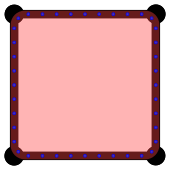
In a stressed-skin design, the skin or outer covering is bonded or pinned to the frame, adding structural rigidity by serving as the triangulating member which resists distortion of the rectangular structure.[1] The skin provides a significant portion of the overall structural rigidity by taking the in-plane shear stress; however, the skin provides very little resistance to out-of-plane loads.[2]: 1

These types of structures may also be called semi-monocoque to distinguish them from monocoque designs. There is some overlap between monocoque, semi-monocoque (stressed skin), and rigid frame structures, depending on the proportion of the structural rigidity contributed by the skin. In a monocoque design, the skin assumes all or most of the stress and the structure has fewer discrete framing elements, sometimes including only longitudinal or lateral members.[3]: 175 In contrast, a rigid frame structure derives only a minor portion of the overall stiffness from the skin, and the discrete framing elements provide the majority.
This stressed skin method of construction is lighter than a full frame structure and not as complex to design as a full monocoque.
History edit

William Fairbairn documented the development of the Britannia and Conwy tubular bridges for the Chester and Holyhead Railway in 1849;[4] in it, Fairbairn describes how Robert Stephenson enlisted his aid to revise Stephenson's original concepts, which would route rail traffic inside riveted steel tubes, supported by chains, with a circular- or egg-shaped cross-section.[4]: 2 Experiments with scale models led Fairbairn to suggest a hollow rectangular beam instead, with longitudinal stringers on top and bottom fixed firmly to structural coverings: "two longitudinal plates, divided by vertical plates so as to form squares, calculated to resist the crushing strain in the first instance, and the lower parts [...], also longitudinal plates, well-connected with riveted joints, and of considerable thickness to resist the tensile strain in the second".[4]: 16 This has been credited as the first instance of stressed skin design, also known as sandwich or double hull.[5]
The first aircraft from the early 1900s were constructed with full frames consisting of wood or steel tube frame members, covered with varnished fabric or plywood, although some companies began developing monocoque structures which were built by bending and laminating thin layers of tulipwood.[6]: 8 Oswald Short patented an all-metal, stressed-skin wing in the early 1920s.[7]: 97 [8] Dr.-Ing Adolf Rohrbach is credited with coining the term "stressed skin" in 1923.[7]: 169 By 1940, duralumin sheets had replaced wood and nearly all new designs used monocoque construction.[6]: 8
The adoption of stressed-skin construction resulted in improved aircraft speed and range, accomplished by reduced drag through smoother surfaces, elimination of external bracing, and providing internal space for retractable landing gear.[9]: 25
Examples edit
Examples include nearly all modern all-metal airplanes, as well as some railway vehicles, buses and motorhomes. The London Transport AEC Routemaster incorporated internal panels riveted to the frames which took most of the structure's shear load. Automobile unibodies are a form of stressed skin as well, as are some framed buildings which lack diagonal bracing.
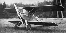
- Dornier-Zeppelin D.I (1918) : first all-metal stressed skin fighter and first with stressed skin wings
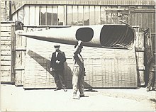
- Zeppelin-Lindau (Dornier) Rs.IV (1918) : first aircraft with an all-metal stressed skin fuselage to fly
- Zeppelin-Staaken E-4/20 (1919) : first all-metal stressed skin four-engine airliner
- Short Silver Streak (1920) : first all-metal British stressed skin aircraft[7]: 164
- Northrop Alpha (1930) : first American all-metal stressed skin aircraft[10]
- GM New Look bus (1959) : stressed-skin bus, over 44,000 built since 1959, and many still in service
References edit
- ^ Sood, Pallika (3 March 2022). "Stressed Skin Floors". Blue Engineering. Retrieved 28 November 2023.
When a sheet of ply[wood] is fixed on the top or bottom of a timber joist, we effectively create a T-shape beam with a large mass, away from the centroid; thus creating a stiffened floor and ultimately, more efficient structural depths. [...] the connection between the elements, provided by the glue and screws, is sufficient to consider the T-section as one full section.
- ^ Bryan, E. R. (1973). The Stressed Skin Design of Steel Buildings. London: Crosby Lockwood Staples. ISBN 0-258-96858-3.
- ^ Standards and Curriculum Division, Training, Bureau of Naval Personnel (1945). Navy Training Courses: Aircraft Metal Work. Government Printing Office. Retrieved 27 November 2023.
{{cite book}}: CS1 maint: multiple names: authors list (link) - ^ a b c Fairbairn, William (1849). An Account of the Construction of the Britannia and Conway Tubular Bridges, with a complete history of their progress, from the conception of the original idea, to the conclusion of the elaborate experiments which determined the exact form and mode of construction ultimately adopted. London: John Weale and Longman, Brown, Green and Longmans. Retrieved 28 November 2023.
- ^ Meyboom, AnnaLisa; Correa, David; Krieg, Oliver David (October 21–26, 2019). Stressed Skin Wood Surface Structures. ACADIA 19: Ubiquity and Autonomy (Proceedings of the 39th Annual Conference). The University of Texas at Austin School of Architecture: Association for Computer Aided Design in Architecture (ACADIA). pp. 470–477. doi:10.52842/conf.acadia.2019.470. ISBN 978-0-578-59179-7.
- ^ a b Gunston, Bill (1988). The Anatomy of Aircraft: Ninety years of development from the Wright Flyer to the B-2 'Stealth' Bomber. Stamford, Connecticut: Longmeadow Press. ISBN 0-681-40714-X.
- ^ a b c Howard, Frank; Gunston, Bill (1972). The Conquest of the Air. New York: Random House. LCCN 72-3818.
- ^ US Patent 1451059A, Hugh Oswald Short, "Wing and like member constructed of metal for aeroplane flying machines and other aircraft", published April 10, 1923
- ^ Haddon, J. D. (1945). An Introduction to Aeronautical Engineering. Vol. II: Structures (Fifth ed.). London: Sir Isaac Pitman & Sons, Ltd. Retrieved 28 November 2023.
- ^ "The NACA and the Modern Airliner - America by Air". airandspace.SI.edu. Retrieved 5 May 2019.
External links edit
- Stressed Skin[permanent dead link]
- Wood to Metal: The Structural Origins of the Modern Airplane