


Summary
In telecommunications, structured cabling is building or campus cabling infrastructure that consists of a number of standardized smaller elements (hence structured) called subsystems. Structured cabling components include twisted pair and optical cabling, patch panels and patch cables.

Overview edit
Structured cabling is the design and installation of a cabling system that will support multiple hardware uses and be suitable for today's needs and those of the future. With a correctly installed system, current and future requirements can be met, and hardware that is added in the future will be supported [1]
Structured cabling design and installation is governed by a set of standards that specify wiring data centers, offices, and apartment buildings for data or voice communications using various kinds of cable, most commonly Category 5e (Cat 5e), Category 6 (Cat 6), and fiber-optic cabling and modular connectors. These standards define how to lay the cabling in various topologies in order to meet the needs of the customer, typically using a central patch panel (which is often mounted in a 19-inch rack), from where each modular connection can be used as needed. Each outlet is then patched into a network switch (normally also rack-mounted) for network use or into an IP or PBX (private branch exchange) telephone system patch panel.
Lines patched as data ports into a network switch require simple straight-through patch cables at each end to connect a computer. Voice patches to PBXs in most countries require an adapter at the remote end to translate the configuration on 8P8C modular connectors into the local standard telephone wall socket. In North America no adapter is needed for certain uses: With ports wired in the preferred standard T568A pattern, for the 6P2C plugs most commonly used for single-line phone equipment (e.g. with RJ11), and 6P4C plugs used for two-line phones without power (e.g. with RJ14) and single-line phones with power (again RJ11), telephone connections are physically and electrically compatible with the larger 8P8C socket, but with ports wired as T568B, which is common but often in violation of the standard, only the first pair, i.e. line 1, works.[a] RJ25 and RJ61 connections are physically but not electrically compatible, and cannot be used. In the United Kingdom, an adapter must be present at the remote end as the 6-pin BT socket is physically incompatible with 8P8C.
It is common to color-code patch panel cables to identify the type of connection, though structured cabling standards do not require it except in the demarcation wall field.[specify]
Cabling standards require that all eight conductors in Cat 5e/6/6A cable be connected.
IP phone systems can run the telephone and the computer on the same wires, eliminating the need for separate phone wiring.
Regardless of copper cable type (Cat 5e/6/6A), the maximum distance is 90 m for the permanent link installation, plus an allowance for a combined 10 m of patch cords at the ends.
Cat 5e and Cat 6 can both effectively run power over Ethernet (PoE) applications up to 90 m. However, due to greater power dissipation in Cat 5e cable, performance and power efficiency are higher when Cat 6A cabling is used to power and connect to PoE devices.[1]
Subsystems edit
Structured cabling consists of six subsystems:[2]
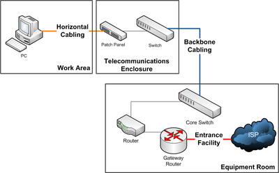
- Entrance facilities is the point where the telephone company network ends and connects with the on-premises wiring belonging to the customer.
- Equipment rooms house equipment and wiring consolidation points that serve the users inside the building or campus.
- Backbone cabling is the inter-building and intra-building cable connections in structured cabling between entrance facilities, equipment rooms and telecommunications closets. Backbone cabling consists of the transmission media, main and intermediate cross-connects and terminations at these locations. This system is mostly used in data centers.
- Horizontal cabling wiring can be standard inside wiring (IW) or plenum cabling and connects telecommunications rooms to individual outlets or work areas on the floor, usually through the wireways, conduits or ceiling spaces of each floor. A horizontal cross-connect is where the horizontal cabling connects to a patch panel or punch up block, which is connected by backbone cabling to the main distribution facility.
- Telecommunications rooms or telecommunications enclosure connects between the backbone cabling and horizontal cabling.
- Work-area components connect end-user equipment to outlets of the horizontal cabling system.
Standards edit
Network cabling standards are used internationally and are published by ISO/IEC, CENELEC and the Telecommunications Industry Association (TIA). Most European countries use CENELEC, International Electrotechnical Commission (IEC) or International Organization for Standardization (ISO) standards. The main CENELEC document is EN50173, which introduces contextual links to the full suite of CENELEC documents. ISO/IEC 11801 heads the ISO/IEC documentation.[3] In the US, the Telecommunications Industry Association issue the ANSI/TIA-568 standards for telecommunications cabling in commercial premises.
See also edit
- 110 block
- American National Standards Institute (ANSI)
- Registered jack, a set of standards for telecommunications cabling termination (including RJ11, RJ15, and RJ45)
- Telecommunication cabling
Notes edit
- ^ Some jack manufacturers warn that their jacks are not designed to accept smaller plugs without damage. See Modular connector § Interchangeability for more information.
References edit
External links edit
- Fiber Optics Tech Consortium (FOTC)