


Summary
Tool management is needed in metalworking so that the information regarding the tools on hand can be uniformly organized and integrated. The information is stored in a database and is registered and applied using tool management. Tool data management consists of specific data fields, graphics and parameters that are essential in production, as opposed to managing general production equipment.
Unlike hand tools, a tool in numerically (digitally) controlled machines is composed of several parts, such as the cutting tool (which may be one piece or comprise a body plus indexable inserts), a collet, and a toolholder with a machine taper. Putting the parts together accurately into an assembly is required to achieve error-free production.
Processing a part with a CNC (computer numerically controlled) machining operation requires several tool assemblies that are documented in a list. Each component, each assembly and each list has an identifier under which the specifications are found. Tool management is divided into documentation (master data) and logistics (transaction data). The documentation includes information needed for a trouble-free and a comprehensible production process. Spare parts, experiences in production and the corresponding data can be managed. Several functions are available to manage, process, print and combine with other applications.
Logistics deals with demand planning, supplies and tool location. This includes, on one hand, the location in the warehouse and the purchasing of individual parts with the corresponding consumption report. It also allows for the planning and coordination of the movements of the assemblies within the shop floor.
In the decades of the 2000s and 2010s, tool management has increasingly moved toward a universal, industry-standard, machine-readable format for encoding tooling information, which makes possible better software, greater automation, and better simulation. ISO 13399 (Cutting tool data representation and exchange) "is an international standard designed to give industry a common language to describe cutting tool products in a digital format."[1]
Master data edit
Master data describes tools' geometric characteristics, composition and usage. The information is divided into specifications and usage instructions. Master data describes the tool in its qualitative aspects, but does not provide quantities and locations.
Components edit

The components are individual elements that can be combined into an assembly. Components are purchased as a unit and stored in a tool room. Cutting components (e.g. inserts) wear out during use and therefore must be purchased and replaced periodically. Non-cutting components (e.g. collets) are practically unlimited. They are often acquired together with a new machine. (Clamping equipment is handled like non-cutting components.)
- Header data is uniformly structured and contains information such as name, supplier product code and a unique item number. Each component is assigned a specific tool type, which defines the number and description of the required data fields. Each component is also linked to a tool category that belongs to a user-specific tree structure, which serves to find the tools according to their technical criteria without indicating the number.
- Descriptive data (geometrical value) vary depending on the type of tool. The data fields are specified in the class list of characteristics. The meaning of the geometrical data fields is illustrated in diagrams and pictures. DIN 4000 recommends diagrams and pictures for their explanation. Varying graphics for different functions are stored either in the database, or with the components through data links.

Generally, four types of graphic illustrations are used:
- 2D drawings, for example, in DXF format according to the ISG/BMG standard for geometrical information
- PDF data of the tool manufacturer as a data sheet with exploded view
- 3D data (e.g. STEP or STL) for the use in CAM systems
- Photos (e.g. JPG) as graphical information
- Cutting data (speed and feed) is stored for the cutting components for optimal chipping efficiency. The different data for varying materials and processing methods, number of revolutions, progressive feed, cooling and production method.
Tool assemblies edit
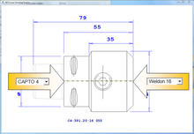
The tool assembly is built using several components. The component at the rear end must connect the machine tool, and the cutting component is found on the other end (ex.: drill or insert). Varying components are used intermediately (ex.: extension, collets) to reach the desired geometry. The assembly documentation describes how the components are assembled, to ensure that the applied geometry in the CAM system matches that of the real tools in the CNC machine.
- Header data contains information such as identification, a specific number and the allotted tool class.
- Geometric fields are computed directly through the data of the applied components. Adjustable tools (ex.: fine drill tools with adjustable diameter) are stored in addition to the assembly data.
- Assembly instructions contain the bill of material as well as the data for the parts assembly that is important for the specific assembly (ex.: adjusting tolerance + 0.03/-0.01 mm).
- Nominal values for the presetting serve as a default in the measuring process with a tool presetting machine. The exact position of the tool and the measuring method can be specified, in addition to the nominal values of the geometry, so that, for example, the left or right corner has to be measured for a grooving tool.
- Cutting data is typically used as a recommendation for the assembly and is adjusted to the specific situation for the assembly. The specifications are improved with the help of practical experience and are automatically made available for NC programming in the CAM system.
Tool lists / manufacturing operation edit
The tool list includes all tool assemblies needed for a machining operation. It is printed as a pick list and is used for commissioning and providing advice for assembly setup. Often instructions and information are not directly related to the tools (e.g. clamping, clamping fixtures, the name of the NC program, etc.) to ensure that all documents for an operation can be viewed together.
- Header data includes information such as name, unique identification and the allocation to the right machines. The combination of "part number + operation", "drawing number + operation" can be used.
- Assembly list contains all the assemblies needed for the operation, along with the designated pocket in the machine (T number, Turret). That list includes those requirements for the assembly, valid for this specific operation only (such as minimum cutting length). The assemblies are listed in the order in which they are used in the NC program.
- The print edition (picking list) is used for the picking of components and assembly of the complete tools in the tool output. It includes the necessary components and their storage location and the important geometric details and tolerances of the complete tool.
Auxiliary tables edit
In addition to the main tool data, auxiliary data tables simplify data acquisition, using values selected from a table. Compared to manual input, this ensures more comfortable and consistent data collection.
- On both sides of a component, match conditions indicate the geometric condition another component must meet to be connected. If a component has on the right side matching conditions such as a next component on the left side, the two can be assembled. The use of match conditions makes searching for matching components easier and more secure. When entering the component into the database, for both sides the right match conditions are selected from a table.
- A list of the work materials is required for the assignment of cutting conditions. Different qualities and additional terms for the materials are contained in the list, and extended by the individual designations as used by the respective enterprise.
- The tool classification is used to organize the tools in technical terms. All tools assigned to the same tool class are suitable for the same task, but they have different sizes. The tool classes are organized in a tree, which is adapted and expanded by the user.
- The tool types with the corresponding images describe the required geometric values and where they are measured. Each tool type is assigned to a class list of characteristics that define the components' data fields.
- The locations are used to specify the location of the assemblies and components in logistics. They are a reflection of the manufacturing environment and include all stands where tools and equipment could stay. They are divided into storage locations, intermediate locations, preparation- and production units (machines). Several locations are grouped into departments. The locations themselves can be divided into individual places. The level of detail and depth of the structure are defined only as far as the logistical aspects are actually necessary.
- The cost centers are used in logistics to evaluate the use of tools in different departments (e.g. turning). With the removal of a component from storage, an indication is specified at its cost center. The cost centers of the tool management must be adjusted with those in the PPS system.
Transaction data (logistics) edit

Logistics is concerned with inventory, storage areas and purchasing. Within logistics, the components and the assemblies are separate. The components differentiate between internal material flow and purchasing goods from external suppliers (stock control).
Stock control of components edit
The logistics of components includes primarily inventory management, requirements planning monitoring of minimum stock levels. When reaching the minimum level, tool management triggers a procurement process. The logistics of tool management use a workplace-tuned user interface and interfaces to storage systems and other facilities within the shop floor. The requirement for coordinated component inventory is a central tool organization in which all components of a production unit are stored at one location, and each withdrawal is recorded reliably.
In-house logistics of components edit
In-house logistics is mainly interested in where a wanted component currently is, and at what cost center it is consumed. This method only consumes wear parts (cutting), the other components (holders, clamping devices) are moved between toolroom, storage places and machine tool. Component booking at the individual cost centers and locations occurs simultaneously when withdrawn/restored to the toolroom. The preparation of tools and resources is triggered by a production order. It refers to a tool list in the master data, that lists required components. Prior to usage in the machine tool, the components are assembled, according to the specifications and work instructions in the tool list. When scheduling production orders, inventory for each component will be checked.
In-house logistics of assemblies edit

Assemblies are built from components, and after usage usually disassembled into components and restored again. From one assembly, multiple copies can be assembled simultaneously, if the components are available in sufficient numbers. The logistics of assemblies refers to the condition and location of these copies.
Each copy of an assembly can typically be in one of three states:
- Not yet assembled (the components are available as individual parts)
- Assembled in intermediate storage (e.g. on a shelf)
- Assembled on the CNC machine
When scheduling a production order, the relevant tools, for the work are known, based on the tool list. Also, known is which assemblies, required for the machining process, are already located on the machine tool. Necessary, but not yet available assemblies are calculated and printed in a net loading list. They either have to be assembled or removed from the intermediate storage. With a coordinated logistic of the assemblies, it is possible to reduce the time required for providing and replacement of assemblies at the machine.
Integration of tool data edit
Tool management guarantees efficient and faultless order processing. Existing knowledge is made generally available and the guidelines stated in the master data are noticed. The integration of tool data enables other applications to use the tool data which is maintained with tool management. Applications either fall back on the tool management database, or the data will be replaced by the interfaces. Especially in CNC manufacturing where several persons are involved in the production process, integration avoids faults, delays and duplicate data recording.
PDM (documentation) edit
In product data management (PDM) systems every product's work plan is saved which comprises CAD Models, the description of working steps and a list of needed equipment. The detailed description of the equipment takes place in tool management because the PDM system does not offer functions and data fields do describe them in detail. It typically offers links to external data. Production orders are generated with the ERP system which links to the work plan in the PDM system. Needed resources such as NC programs, tools, and instructions are requested in production from tool management. Integration guarantees availability of the information in tool management. The basic objective for integration is a systematic numbering of documents and resources.
ERP (purchasing) edit
The ERP system plans raw material, consumable items and other resources. It closely connects with PDM and assumes the tasks of materials management and logistics. Related to the tools, this concerns the consumable components. If the component inventory is conducted with tool management, purchase orders will be transmitted as purchase requisitions to the ERP system which issues the actual order. This requires that the products be registered in both systems with the same number. Additionally all internal stock movements of tool components for the costing can be handed to the ERP system with the integration.
CAM edit
CAM systems generate the G-Code commands (NC program) for the CNC machine. Geometry, description and cutting conditions are selected and received directly from tool management. This ensures that all tools used are documented and consistent with the reality in the workshop. From the CAM system, all tools used in an NC program are automatically saved as tool lists in tool management. This ensures the correct use of the tools during the preparation of the work process.
Storage systems edit
Besides conventional tool cabinets, storage systems that provide the operator with the shelf containing the desired product are often used. The relationship between the item number and the storage location is saved in tool management. When booking a tool removal in the logistics area of tool management the storage system is operated automatically. Alternatively, assignment of storage locations can be configured in the storage system. The removal is then performed on the storage system and the inventory change is transmitted to tool management.
Presetting edit

At the processing to the tools' positioning the CNC machine needs their exact measurements. Therefore, the length and diameter of the complete tools must be entered when connecting them to the machine. These settings of the tools can be measured with an external pre-setter. Convenient pre-setters assume the nominal values, tolerances and designation from tool management and pass the measured values directly to the CNC machine. The integration of tool management with the pre-setters takes place in the exchange format of the respective equipment manufacturers and includes graphics and information about the measurement method.
Tool catalogues edit
To reduce the cost of initial data acquisition of the components in tool management, tool manufacturers provide the data and graphics in an appropriately conditioned form. For technical data, the DIN 4000 and the ISO 13399 exchange formats are currently used. Where required, 2D graphics are provided in accordance with the ISG / BMG DXF standard. For 3D graphics, no standard is defined. Normally, STL and STEP format are offered and axis position is chosen according to the application on the machine.
Motivation for tool management edit
Greater ROI edit
The bottom-line motivation for tool management, as with all manufacturing technologies, is greater return on investment through higher efficiency. This is achieved as follows:
Utilization of new technologies edit
Rising demands in design and quality, combined with time and cost pressures, force companies to regularly invest in more efficient equipment and procedures. Modern CNC-Machines (i.e. Mill-Turn-Machines) are highly productive, however they demand rigorous preparation and application. A prerequisite for their successful use is therefore the simultaneous adaptation of the organization together with the management of necessary operational information. The knowledge can subsequently be included in operational procedures and made available for each necessary task. This avoids the flawed or incomplete information that can interrupt production.
Supplying the right information edit
Newly purchased equipment is supplied with specific usage information (i.e. cutting data with tools). This information is found in supplier specific documentation (i.e. the maximum allowed diameter of a fine boring tool). Before the new acquisition can be used, the data must be integrated in the company-specific task format. (i.e. The exact setup values for a required fine boring tool). Furthermore, this information must be made available to all participating work areas. (i.e. the exact adjusted diameter must be made known to the NC programming and tool store departments). Processed company information is then made available as part data instructions (i.e. appropriate cutting values for a particular tools usage with a specified material) and must be managed and integrated within workflows to prevent production capacity loss or shortening tool life.
Make information more easily available edit
Tool and production data is managed within a company database and in a specific format. For this purpose a software application provides accessed across all departments and used without registering duplicate data. Such data can be utilized by other software applications (i.e. CAM-Systems, tool pre-setters, shop floor logistics). Suitable interfaces are integrated to secure smooth, seamless workflows. Central data management reduces errors and production stoppages.
Value edit
The importance of exchanging information between operational areas varies according to the type of company. Generally it can be said that missing or unclear information is the source of errors that cost capacity and generate delays and inefficient workflow. Manual interfaces and information passed by word of mouth are potential error sources and obstacles. Especially important are binding specifications that are involved in complex work situations to reduce the chance of machine damage as well as the risks involved with defective deliveries.
References edit
- ^ Albert, Mark (2016-01-01), "Standard tool classification for better data communication", Modern Machine Shop.
- Hans B. Kief, Helmuth A. Roschiwal: NC/CNC Handbuch 2007/2008. Hanser, München 2007, ISBN 978-3-446-40943-9.Leseprobe