


Summary
The Type 277 was a surface search and secondary aircraft early warning radar used by the Royal Navy and allies during World War II and the post-war era. It was a major update of the earlier Type 271 radar, offering much more power, better signal processing, new displays, and new antennas with greatly improved performance and much simpler mounting requirements. It allowed a radar with performance formerly found only on cruisers and battleships to be fitted even to the smallest corvettes. It began to replace the 271 in 1943 and was widespread by the end of the year.
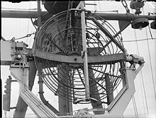 Type 277 antenna on HMS Swiftsure | |
| Country of origin | UK |
|---|---|
| Introduced | 1943 |
| Type | Sea-surface search, early warning |
| Frequency | 2950 ±50 MHz (S-band) |
| PRF | 500 Hz |
| Beamwidth | 6.2º |
| Pulsewidth | 1.8 or 0.7 µs |
| RPM | 0 to 16 rpm |
| Range | 1 to 11 NM (1.9–20.4 km) |
| Diameter | 4.5 ft (1.4 m) |
| Azimuth | 360º |
| Precision | ~2º, 250 yards range |
| Power | 500 kW |
| Other Names | Type 276, 293 |
| Related | Type 271/2/3, 294/5, 980 to 984, CD No.1 Mk. VI, AMES Type 50 to 56 |
The Type 271 was one of the first microwave frequency radars to enter service, when microwave electronics design was in its infancy. While it was still being fitted to escort ships during 1941 and 1942, great strides in technique were being made in cavity magnetron, waveguide, antenna design and general electronics. Those upgrades that could be easily combined with the existing systems became the 271 Mark IV models, while those that required longer to develop were originally known as the Mark V. Given the magnitude of the changes, in March 1943 the Mark Vs were renamed as the 277 series.
The 277 used a 500 kW magnetron, compared to the 271's 5 kW, added a much higher gain antenna that was stabilized in pitch, replaced the coaxial cable signal feeds with waveguide, and added a plan-position indicator (PPI) system with several remote displays. While the 271 offered performance to about 3 miles (4.8 km) against a U-boat and had to communicate with the commanders by voice tube, the 277 was limited only by the radar horizon and its display could be read directly on the bridge on larger ships.
The 277 spawned several modified versions, including Type 276 for destroyers and Type 293 for dedicated air warning. These were so powerful that they were adapted for other roles by the British Army for coast watching and artillery spotting, and the Royal Air Force as Chain Home Extra Low to counter German aircraft attacking at very low altitude. Improvements to the electronics continued, leading to the P and Q models which arrived in 1945. Q models remained in service well into the 1950s.
History edit
Type 271 edit

The Type 271 was one of the first microwave-frequency radars to reach service, with the first example entering testing in March 1941 and being declared operational in May. At this time, the entire field of microwaves was in its infancy, the requisite cavity magnetron and sealed crystal detectors having been developed only a year earlier. Nevertheless, the 271 proved to be an extremely useful device, small enough to fit on corvettes and having enough optical resolution to detect a U-boat within about 3 miles (4.8 km).[1]
The original Type 271 was intended for small ships where the antenna could be placed directly on the top of the bridge. The operator manually swung the antenna back and forth using a steering wheel connected to a shaft passing through the roof. The Type 272 replaced the shaft with a Bowden cable and updated the electronics to allow it to send its data through as much as 40 feet (12 m) of coaxial cable, intended to allow the antenna to be mounted on the mast of medium-sized ships like destroyers. In practice, the 272 was considered a failure.[2]
The Type 273 was similar to the 272 but replaced the original "cheese" antenna with a much larger parabolic reflector with much higher antenna gain, more than offsetting the signal losses in the coaxial cable. Because this style of antenna had a pencil beam rather than the fan-shaped beam of the cheese-style antenna, in order to keep it aimed at the horizon as the ship pitched and rolled it needed to be mechanically stabilized using a gyroscopic platform. This version was intended for larger ships like cruisers and battleships that had ample room on their mast to install a larger antenna. These proved extremely successful and unstabilized versions were soon picked up by the British Army for coast defense.[3]
Q models edit

While the bulk of the 271 units were being installed, great strides were being made in the electronics related to microwave use. Crystal detectors, a key component needed for practical microwave receivers, were being constantly improved. New models arrived from the United States that were both more robust than the early UK models and had far less electronic noise, from about 20 dB of the early models used in the 271 prototypes, to as little as 14 dB by 1943. The magnetron underwent several rapid improvements in power levels, first into the 100 kW range, and by 1943 was starting to approach 1 MW. These two improvements alone offered the possibility of dramatically increasing the range of a radar system.[4]
During the same period, the art of waveguide and feed horn design was improving rapidly, replacing the older coaxial cables and dipole antennas that had significant losses at microwave frequencies. Reflector designs, and the stabilized mounts needed to accurately point them, were likewise improving. A key advance was the soft Sutton tube that allowed a single antenna to be used for both broadcast and reception. Finally, new concepts in signal processing were allowing for the construction of the first radar lock-on systems, that allowed a radar to automatically track a target with accuracies far beyond what a human operator could achieve.[5]
After some consideration, it was decided to roll up several of the simplest improvements into a new design, the "Q" models, also known as Mark IV. These would use the newer CV56 magnetrons at 70 kW along with a new waveguide system to feed the antennas. After minor changes as a result of field testing, the first production Q models were being installed in May 1942 and had largely replaced the earlier models by late 1943.[6]
Mark V edit
With the main issues with the 271 solved by the Q models, one major issue remained. The Type 272, the remote-reading version of the original 271, was generally considered a failure. The unit remained difficult to mount and the long distance between it and the receiver electronics led to poor performance.[7]
The introduction of the soft Sutton tube allowed a single antenna to be used for both transmission and reception, and this was seen as a way to help address this issue. The lower weight of a single antenna would allow a larger reflector to be used, offsetting the losses in the long connection in the same fashion as the 273. Furthermore, as the waveguide concept was better understood, it became possible to build a waveguide with a rotating joint. This would allow the coaxial cable to be replaced with a waveguide, which would both allow 360 degree rotation[a] as well as greatly reducing the signal losses.[8]
Ultimately the decision was made to move to two new antenna designs. One would use the 4.5 foot (1.4 m) reflector from the Army's Coast Defense versions of the 271, further improving gain over the 3 foot (0.91 m) 273. Because there was only one of these "dishes", this would be able to be mounted on a stabilized fitting even on roof of the smallest escorts. This became known as the Type 271 Mark V. A second version, retaining the original cheese-style antenna, would be placed in a new housing and become the Type 272 Mark V for destroyers. The light weight of this antenna allowed it to be mounted even on a relatively small mast. No separate 273 would be needed, the larger 271 Mark V could also be used on larger ships which already had the room to mount it. Although the 272 Mark V would have the smaller antenna, the new magnetron would so increase its power that its performance was expected to at least match the original 273Q.[9]
Prototype system edit
The main problem with adapting the new magnetron was that its 500 kW output demanded a 1 MW power supply. This required a new design using a discharge-line modulator of much more robust design, as it not only reached higher peak power but its continual output averaged 1 kW.[8]
To test the system as a whole, an experimental version of the new system was built during the summer of 1942, Type 273S Mark V. This consisted of an operating cabin mounted on a gun carriage that allowed it to be rotated. On top of the cabin was an antenna consisting of a single waveguide-fed cheese-type reflector enlarged to 15 by 2.5 feet (4.57 by 0.76 m). This was tested on the shore near RAF Ventnor.[10]
During this period, the Navy was introducing the Type 281 radar for air warning on larger ships. This metric-wavelength system was mounted relatively low on the ships and thus had a limited radar horizon. Aircraft only became visible to the radar at 40 miles (64 km) if they were flying above 4,000 ft altitude, and there was a strong desire to "fill the gap" below this altitude. Considerable interest was generated by the new Mark V's and whether they could be adapted to this secondary role.[7]
To test this concept, the 273S was further modified with the addition of a separate IFF Mark III receiver on top of the cheese. Its antenna consisted of a series of vertical poles mounted along the back of the cheese, with metal netting hung from the poles to form a second cylindrical section. A standard two-element Yagi antenna was positioned in front of the reflector.[11]
After modification it was taken to an Army test site in North Wales at Great Orme, about 460 ft above sea level.[10] In tests between December 1942 and February 1943 it demonstrated its ability to detect a Bristol Beaufighter at 80 miles (130 km) while flying at 8,000 ft altitude. At that altitude the radar horizon was about 110 miles (180 km), so this was excellent performance. This was when it was manually rotated in A-scope fashion, it was expected that this would be reduced to perhaps 60 miles (97 km) in a PPI system rotating at 2 to 4 rpm.[12]
Type 277T edit
In March 1943 during a renaming exercise, the 271 and 272 Mark V's became the Type 277 and Type 276, respectively. At the same time, the 273S Mark V was renamed 277T.[7][b]
The performance at Orne was so impressive that the 277T was ordered into production at Allen West & Co., Metrovick and the Marconi Company for Army and Royal Air Force (RAF) use as Chain Home Extra Low (CHEL). The first production model arrived in March 1943 and put into operation at Capel-le-Ferne, Dover. This proved itself extremely effective against the Focke-Wulf Fw 190 "tip-n-run" raiders that had been causing so much trouble during this period. The 277T could detect them shortly after they passed the French coastline.[13] The system was able to provide air warning of the impending attack on Ashford School in March 1943, saving the lives of the students in the Girls School.[12][14]
Type 277S (for Static, as in non-moving) featured a further improvement to the mounting system, replacing the gun trailer with a custom-designed carriage. These began to arrive in the middle of 1943, with the first sent to Sæból, Iceland. Some units were sent to the continent during the D-Day landings.[12]
Type 277X edit
While the 277T was testing the general performance of the electronics, progress was being made on the naval version of the antenna system on a one-off system known as 277X. The new 4.5 foot dish was made of pressed sheet metal and mounted in a yoke (or fork) mount. The elevation axis of the yoke had a motor on one of the bearings to provide vertical stabilization. A gyroscope at the motor provided the horizon reference. The waveguide was attached at the bearing opposite the vertical motor, running up and over the top of the reflector and then straight down the front of it with a hole in the middle to provide the feedhorn. Having the waveguide run down the entire face meant it could be connected to the reflector at the top and bottom, providing excellent mechanical support.[15]
There was no horizontal stabilization required as the antenna was spinning continually and referenced to north with a Remote Reading Compass. The rotation rate could be controlled between 0 and 16 rpm, as well as offering a hand-controlled pointing mode. Elevation could also be adjusted by hand, displacing it from the gyro-provided horizon, allowing it to scan at higher angles if need be. Two displays were used, a PPI from the experimental Outfit JE display from EMI, and a second display used to measure range. The later, developed by the Air Ministry's Telecommunications Research Establishment (TRE) used a cursor[c] that allowed the operator to pick out one "blip" on the display and read the elevation and use the range measurement to solve for the altitude.[15]
277X was mounted to Saltburn for trials, in spite of this ship's abnormally low mounting point at 27 feet (8.2 m) above the waterline. There was no concern about performance; the new transmitter and greatly improved antenna gain meant the system was providing about 25 times the beam energy. For this installation, the waveguide was about 100 feet (30 m) long, which in theory resulted in only 3 dB losses.[d] In practice, they found that the various bends and other effects led to reflections and inefficient coupling between the receiver and the waveguide. This had not been seen on the 277T due to its much shorter run, but new experiments on those systems confirmed the problem and new techniques were developed to tune the waveguide.[16]
There were two main testing periods on Saltburn, the first from 8 to 20 April 1943 off Lough Foyle, and the second from 2 to 5 May off the Isle of Man. Poor weather was a factor during both tests, which led to less than satisfactory tests against aircraft. They were able to demonstrate detection against a medium bomber at 40 miles (64 km) on the PPI, and height finding at 20 miles (32 km). The poor weather did have the advantage of demonstrating the stabilization system was working well.[9]
Type 277 edit
As testing of the 277X progressed, a new antenna using a reflector made of wire mesh instead of sheet metal was introduced. This Outfit AUK had almost no effect on performance, but was both lighter and had less wind load.[17] Production versions of the 277 with AUK began to arrive in early 1943 and installations were widespread by mid-1943.[18]
Type 276 edit

The basic idea behind the 276 was to use the original 271Q cheese-style antenna and a soft Sutton tube to allow the receiver and transmitter to share a single antenna. This would reduce the size and weight of the mast-top installation. When combined with the new magnetron from the 277 and the use of a waveguide, it was calculated that it would offer almost exactly the same performance as the much larger 273Q parabolic antennas, and thus provide an excellent replacement for the failed 272.[19]
As the interest in aircraft detection grew, some estimates of its performance in this role were made. The antenna's 180 gain was much less than the 277's 800. As it had been predicted the 277 would detect a light bomber at 45 miles (72 km), this implied the 276 would do the same at about 21 miles (34 km). It was noted that the original 4 foot (1.2 m) by 10 inches (250 mm) cheese antenna would have limited vertical coverage, which meant it would have difficulty tracking aircraft at higher altitudes. At the end of 1942, a slight modification was made to decrease the vertical size to 10 inches (250 mm), spreading the beam out more vertically from 10 to 20 degrees at the cost of some loss of gain.[20]
A further change, seemingly trivial in retrospect, was to eliminate the cylindrical radome and replace it with a single sheet of perspex sealing the front of the cheese. The resulting Outfit AUJ was significantly easier to mount on a ship's mast than the earlier designs. The first AUJ was fitted to HMS Tuscan. The waveguide on Tuscan was slightly longer than normal at 70 feet (21 m), but any loss in performance was offset by a switch from brass to low-loss copper.[e] The antenna was also slightly closer to the sea, at 63 feet (19 m).[19]
In testing, the 276X was able to detect HMS Kempenfelt[f] at 29,000 yards (27,000 m), effectively identical to the performance of the 273Q from the 100 foot (30 m) mount on King George V, as had been predicted.[19]
Type 293 edit
Combat in the Mediterranean, especially during the Allied invasion of Sicily and the Italian mainland, was marked by significant air attacks by Italian and German aircraft. It was also marked by the relatively poor performance of anti-aircraft gunnery. To improve their performance, the Navy grew increasingly interested in a radar that was dedicated to the continual plotting of the location of aircraft at close range, when their relative position to the ship was changing rapidly. The idea was to fit all ships of the destroyer size and larger to allow the entire task force to operate effectively against aircraft. A formal requirement for this new "Target Indication", or "TI", role was released in December 1942.[10]
Some testing against aircraft had been carried out using the original parabolic antennas of the 273Q on King George V, but these were generally unsatisfactory. The main problem was that using a conventional A-scope and hand pointing did not allow targets to be tracked continually with any accuracy, and made searching for more aircraft while tracking another very difficult. A PPI display, which showed all the aircraft around the ship at the same time offered a great improvement. Further testing using a PPI display on the bridge of HMS Rother was carried out in July 1943.[20]
The main problem with using the existing systems for aircraft tracking was that the new parabolic antennas had very narrow beams that were not suitable for continually scanning to the high angles that the TI role desired, up to 70 degrees above the ship. A fan-shaped beam like the one generated by the original 271 or new 276 cheese antennas would be much more suitable. A new antenna was developed, Outfit AUR, which was somewhat larger than the 276's, at 6 feet (1.8 m) wide and only 4 inches (100 mm) high. Such an installation, combining the 277's electronics with the AUR antenna would be known as the Type 293.[10]
For larger ships with sufficient room to mount more than one radar antenna, both the parabolic AUJ and the AUR cheese could be fitted. The electronics could then switch from one to the other as required. For the much smaller escorts that lacked long-range anti-aircraft weapons, no TI radar was needed anyway. This left a problem for destroyers and small cruisers; these ships lacked the room to mount both the AUJ for surface search and AUR for TI, and would have to make do with one or the other. As the TI role gained importance, it was planned to use the AUR and have it act in both roles.[20] The mounting was designed so the 293 or 276 antennas could be easily swapped.[19]
To test the performance of the system in the surface role, the first Type 293X was fitted to HMS Janus. This was connected to the operator's cabin via a 67 foot (20 m) long brass waveguide.[g] This was tested between 27 August and 4 September 1943 in the Pentland Firth area.[21]
For the surface warning role, tests were carried out by Janus against HMS Obedient acting as a target. The 293 could only detect Obedient at 24,000 yards (22,000 m), a range at which only the lower 4 feet (1.2 m) of her hull were still below the radar horizon. In comparison, the 273Q had demonstrated the ability to detect a destroyer when only the top parts of its mast were above the horizon, and the 276 was expected to provide similar range. This meant the 293 was rather limited in this secondary role.[19]
Outfit AQR edit

The less than satisfactory performance by the 293X in the surface role led to some reevaluation of the idea of mounting the 293 on destroyers. By this time the 276 was in production use, and had demonstrated much better performance against aircraft than the 293, although its performance fell off against targets flying over 8,000 feet altitude, as would be expected from its broadcast pattern.[19]
This led to the decision to return to the original 271Q cheese antenna for the 276, instead of the compressed higher-angle design. This was improved on by a small but important modification; instead of placing the antenna in a radome, the system was protected simply by covering the front of the cheese with a perspex plate, as in the case of the 293. By this time a number of destroyers had received the 293, and from autumn 1943 these were replaced with the 276 as they came in for maintenance.[19]
All of this testing suggested that a combined TI/surface radar was possible, but the antenna would have to have about three times the gain of the original AUR antenna. This led to yet another new antenna design, the Outfit AQR, which was larger at 8 feet (2.4 m) wide and 7.5 inches (190 mm) high.[22] In contrast to earlier designs that used shaping of the reflector to produce the focused beam, the AQR used a rectangular reflector consisting of a large metal bar at the top and bottom of the rectangle, and four smaller bars running parallel to them forming the reflector body. This meant it had much lower wind loading than the earlier solid designs so its larger size did not overload the mounting. Focussing of the beam was now provided by the feed horn instead of the reflector shaping. This provided a gain of about 220, much greater than the 276's AUJ. When production AQR's finally arrived in 1945, the AUJ was declared obsolete and replaced with the AQR.[23]
An even larger version of the AQR, Outfit ANS, was under development for cruisers, but was not fitted until the postwar period. Known as Type 293Q, it was able to detect any aircraft at 18 miles (29 km) range at any altitude from the horizon to 35,000 ft.[23]
Further testing edit

In March 1944, the 277 aboard escort carrier HMS Campania was used in a series of tests against the ship's Fairey Fulmar aircraft. Campania also carried the older Type 281 radar for air warning, which allowed the two to make comparative measurements. One problem with the 281 was that it did not offer altitude measurements, so a series of experiments started to use the 281 for tracking and the 277 for height finding. To do this, the 277 was locked in azimuth and then rotated manually through elevation to maximize the signal. The angle was then used to calculate the altitude.[17]
As part of these tests, a significant amount of attention was paid to the detection capabilities of the 277. This led to a series of probability charts which demonstrated that the detection was roughly linear with range for a medium-altitude target at 2,000 ft altitude, from 100 percent at ranges under 5 nautical miles (9.3 km; 5.8 mi) to about 80% at 10 nautical miles (19 km; 12 mi), to about zero at 40 nautical miles (74 km; 46 mi).[24]
As the Type 276 and Type 293 used the same fixed-speed 10 rpm mount, it had not been possible to perform significant testing of its ability to detect aircraft. Campania now turned its attention to the question of the best scanning speed, carrying out a series of runs at 10 and 16 rpm, and at a variety of much slower speeds using the variable-speed control. These revealed there was no obvious effect on detection probability when running at slower speeds between 2.25 and 2.5 rpm.[25]
Priority for the 277 was given to the larger ships, where the increase in performance was welcome, whereas the 271Q on the escorts was already performing adequately. In late 1944, the Navy became aware of the German efforts to fit the Schnorkel to their U-boat fleet. This led to the 277 being prioritized for the escorts to counter this threat.[25]
In September 1944, corvette HMCS Copper Cliff was fitted with the AUJ at the top of its 65 foot (20 m) mast, rather than the typical location on the bridgework. This gave it a radar horizon of 9.5 miles (15.3 km). In tests in Firth of Clyde and the North Channel, Copper Cliff was able to reliably detect a surfaced submarine at 11 miles (18 km) when only part of the conning tower was visible. Against a Schnorkel, which was only 3 feet (0.91 m) high, the range was reduced to about 5.5 miles (8.9 km), and when closer to the surface it became lost in the radar clutter of the waves.[25]
P and Q models edit

Although the 277 incorporated many of the advancements available when it was designed in 1943, by 1944 further progress had introduced new systems that were highly desirable. Among these was a new crystal detector combined with the Sutton tube switch that could be mounted directly to the waveguide instead of needing a length of coax to connect the switch to the waveguide. This eliminated the need to constantly tune the system for best performance. Another change was to move from the early-war standard of 60 MHz intermediate frequency to a new receiver strip working at 13.5 MHz.[h] These changes reduced the receiver system noise by about 2 dB.[26]
In addition, new anti-jamming systems were added. This consisted of a third stage in the IF receiver that could optionally be switched in if jamming was seen. This reduced the bandwidth of the receiver to 0.5 MHz, filtering out wide-band signals. Provisions were added for further filters to be added in the future, if needed.[26]
By this time the original 271 equipment setup, largely retained for 277, had been repeatedly enlarged as new repeater displays were added. There was also a strong desire to rationalize all the connections, which proved to be a continual maintenance problem. A new set of radar office panels was designed to incorporate all of these changes, which resulted in the 277P and 293P.[26]
Production units would be available in mid-1945, but by late 1944 there was a major effort underway to perform major maintenance on many of the major fleet units in preparation for their shift to the Pacific theatre. To get these units equipped, Project Bubbly was launched as a "limited emergency" production and the battleship HMS Anson received the first unit in March 1945. Conversion kits were shipped out for this ships that had already left for the Far East.[26]
As air attacks against ships had been a significant feature of the Pacific war, there was also a desire to further improve the performance of the 277 and 293. By this time a number of ships had been equipped for the new "Fighter Direction" role, commanding wide-area aircraft operations. For this role even the 277P had too short range, and a new 8 foot (2.4 m) diameter reflector was designed, clipped off to 6 foot (1.8 m) wide. To reduce clutter, this radar used vertical polarization, which scattered from the waves and reduced the reflected signal.[27]
The resulting system, Type 277Q, arrived too late for Project Bubbly and did not see service until the post-war era. In tests aboard HMS Illustrious in March 1947, 277Q provided reliable detection in the TI role out to 85 miles (137 km) and heightfinding to 55 miles (89 km), dramatic improvements on the 293. The system was extremely effective and remained in service for many years.[27]
Fighter direction radars edit
Operations in the Mediterranean demonstrated the need to better coordinate fighter aircraft operations to successfully counterattack the German and Italian air fleets. In 1942, some experiments were carried out by fitting a PPI display with a skiatron to produce a long-lasting map-like display for the Type 281. The display proved successful, but the 281 lacked resolution and was subject to strong returns from any nearby land that would swamp the display.[27]
Tests of the 277T in late 1942 were extremely promising, and later that year a Staff Requirement was issued for a dedicated Fighter Direction radar, or FD. The design had to be able to detect any aircraft above 35,000 ft to 80 miles (130 km) range and also offer height finding with an accuracy of 1,000 ft at 40 to 80 miles, and 500 ft accuracy below 40 miles range. It was understood that getting the required performance would require a large, heavy and fully stabilized antenna system, and would thus be carried only by carriers and dedicated Fighter Direction Ships.[28]
Initial calculations showed that a cheese-type antenna 12 feet (3.7 m) wide with a 17 inches (430 mm) gap between the top and bottom could provide the same gain as the 277's parabolic dish. It had been estimated that the 277 would have about 45 miles (72 km) range against aircraft, so this meant there was another doubling of range required to meet the requirement. To fill the performance gap, plans were made to use a magnetron running at 2 MW and having a longer 5 us pulse length, thus producing ten times as much power as the existing systems.[28]
As the Staff Requirement demanded height finding while the system continued sweeping, a completely separate height finder system would be needed. This was a relatively new concept, but a solution was quickly developed. A second receive-only antenna would be fitted above the main cheese antenna. By fitting four feedhorns into the waveguide in front of the reflector, a reception pattern with multiple stacked vertical lobes would be developed. This required the development of a new waveguide with four rotating joints.[29]
The new system was given the name Type 295, and if the equipment were available before the new magnetron, an interim Type 294 using the existing Type 277 magnetron was also specified. By 1944 it was clear the height finding system did not work as expected, which put both plans on hold. It was also clear that the 2 MW magnetron would not be available in time to equip HMS Eagle, which was then under construction at Harland and Wolff.[30]
As both designs relied on the multi-lobe height finder, and that seemed to be an unworkable concept, the Navy issued new requirements using Type 277 magnetrons in separate PPI and height finder radars. These became the Type 980 and 291, respectively. These proved problematic as well, and finally entered service as Type 982 and Type 983.[31]
Other uses edit
The Navy units led the development of large magnetron-based radars through the entire war period, outpacing those developments made by the Air Force and Army. For this reason, many late-war land-based radars used by both forces were versions of Navy equipment with few changes needed. This was true for the Type 277, which formed the basis of a number of land-based radar systems.[32]
CD Mark VI edit
As testing of the 277T began to turn in superb results, the British Army adopted it, almost without change, as Radar, Coast Defence, Number 1, Mark VI, or CD No. 1 Mk. VI for short. The CD radars were used to look for ships in the English Channel, and for this role had to be able to scan close to the surface. Early CD sets were based on the common 1.5 m electronics widely used by both the Army and RAF, but they had relatively low accuracy. They had moved to the 271P as Mark IV and the 271 as Mark V, and now adopted 277T as Mark VI. With the change to the 277, the accuracy was enough to pick out individual E-boats as they left the French coast.[33][i]
AMES Type 50 edit
When the Army introduced its first Coast Defense radars, the Air Ministry took a number of them and placed them on high towers so they could see low-flying aircraft. These installations became the Chain Home Low systems, able to detect aircraft as low as 500 ft at ranges that allowed interceptions to be arranged. These were given the official name AMES Type 2, although this name was rarely used in practice.[34]
When the Army moved CD to the 271P, the RAF did the same, referring to them officially as AMES Type 30, with a series of such systems given different type numbers based on the differences of their mounting systems. When 271P gave way to 271Q, the new systems were deployed under the name Type 40, and in turn became Type 50 when they moved to the 277. The systems were referred to generically as Chain Home Extra Low (CHEL).[34]
The AMES Type 50 was essentially identical to the 277T, using a cheese reflector that had been used on the prototype. The Type 52 moved to parabolic reflectors for additional performance. This produced a series of designs with 10 foot (3.0 m) diameter reflectors, Types 52 through 56, that differed solely in their mounting system. To confuse matters, any one of these may be referred to as CHEL.[34]
CHEL and CD were often one and the same system, simply two names for the same installation depending who was referring to it, the Army or Air Force.[34][35] To further confuse matters, if the radar was located close to a coastal artillery site, the Army then referred to it as Radar, Coast Artillery, or CA for short.[36]
AMES Type 13 and 14 edit
In 1941, the Royal Air Force (RAF) began introducing a new land-based radar system known as AMES Type 7. In service, it became clear that the accuracy of the Type 7's lobe switching system for height measurement was not optimal, and using it also required the power of the transmitter to be split in half and thus lowered range when used. A requirement for a dedicated height finder was developed, and this emerged as the AMES Type 13, which was sometimes known as "Centimetric Height", or "CMH".[35] As experiments with the 277T were proving highly successful, the decision was made to use this as the basis for the Type 13.[37][38]
The main difference between the Type 13 and the 277 was the antenna. For the height-finding role the goal is to have a beam that is narrow vertically and wide horizontally, the opposite of that is desired for a PPI display. This can be easily accomplished using a cheese-style antenna, rotated so the long-axis is vertical. The Type 13 used a massive 20 foot (6.1 m) high by 18 inches (460 mm) wide cheese. The system was so large that it was structurally unstable, so it was built as two connected side-by-side units, fed from a waveguide with two feed horns, one for each side.[39]
As the Type 13 was beginning to enter production, the RAF was arguing about the introduction of the Window system to block German radars. RAF Fighter Command felt the Germans would quickly make their own window and use it against the RAF's 1.5 m radars, like Type 7. In response, production of Type 13 was redirected to the Type 14, which was essentially a Type 13 turned on its side, returning to a horizontal layout like the CD and CHELs. This allowed it to scan the horizon instead of up and down, producing a PPI display.[38]
When attention turned back to the Type 13, tests demonstrated disappointing performance.[40] Existing units were used as PPI units by turning off the "nodding" system and manually rotating it to scan the horizon. Several improvements were made, but the system was not truly satisfactory until the Mark V, introduced post-war. The Mark V used an entirely new antenna consisting of a cylindrical reflector made of vertical metal tubes.[39] When combined with a Type 14, the two-unit system was known as a Type 21.[41]
Description edit
This description is based on the production model 277, with differences between models noted as required.
Antenna layout edit
The standard antenna system for the 277 consisted of a wire-mesh parabolic dish, 4.5 feet (1.4 m) in diameter. The signal was fed to and from the antenna using a waveguide that spanned the diameter of the dish, running vertically across the front. This allowed it to be firmly mounted at the top and bottom of the reflector itself, rather than needing a separate support structure.[15] The system had an overall gain of 800, although the later dish used on the 277Q increased this to 1750 and the smaller cheese antenna on the 276 reduced it to 180.[42]
The assembly was mounted in a fork mount that connected to the reflector on the left and right extremes. The drive motor for the vertical stabilization was on the left arm of the fork, as viewed from the front. A rotating joint for the waveguide was located on the right side, and the signal was fed from this location to the main waveguide and feed horn with a short length of pipe running from the joint to the top of the reflector. The other side of the joint led to a waveguide running through the fork to the bottom of the mount, where a second rotating joint led to the radar cabin.[15]
Electronics edit
The 277's electronics were state-of-the-art for 1944, having introduced several new systems to improve performance over the 271. In particular, US-made detector crystals improved the receiver noise to 14 to 16 dB, whereas the 271 was about 2 dB higher.[42]
The entire equipment system was packaged similar to the later 271P and Q models, consisting of a single cabinet with two large boxes on the bottom and middle, and a much smaller unit on top. The lowest unit was the power supply and pulse-forming system, with the receiver and display on the middle, and tuner on top.[43]
Displays and interpretation edit
The 277 used a plan-position indicator for its primary display, based on a large (for the era) 9 inches (230 mm) cathode ray tube (CTR). On a PPI, a time base generator pulls the beam from the center of the tube to its outer circumference in the same time it takes a radar signal to travel to its maximum distance and back again. The amplified return signal controls the brightness of the beam, causing strong reflections to produce a "blip" on the display.[43]
As the antenna rotated, a mechanical system rotated the display at the same speed, referenced to magnetic north. This meant that reflections at certain angles to the ship appeared in that position on the display, relative to north. As the beam had a finite width, the resulting "blips" were short arcs, not individual spots. Because of the timing of the beam's movement, the distance of the blip from the center of the display revealed the target's range.[43]
Notes edit
- ^ When connected using a coaxial cable, the antenna could only be rotated so much before the cable was wrapped around the rotating shaft.
- ^ Existing sources are not clear on the meaning of the "T". Navy nomenclature rules reserved letters M through Q for new versions of existing designs, and R for optional ranging panels and S for "static" or "shore" based systems. T would normally be used for prototypes or "test" systems, but that was not the case here. The new name may have been required simply because the Mark IV became 271Q and they ran out of letters.
- ^ Or "strobe" as it was known at the time.
- ^ For comparison, a coax of the same length was expected to have about 20 dB losses.
- ^ Copper lost 0.025 dB per metre, compared to 0.05 for brass.[20]
- ^ It is not clear if this is referring to the earlier HMS Kempenfelt (I18), by this time known as HMCS Assiniboine, or the later ship of the same name, HMS Kempenfelt (R03). Images of R03 show a Type 271, so this article assume it was that ship after the 271 was upgraded.
- ^ This was the second and last fitting using brass. All future waveguides were made of copper to improve performance.[20]
- ^ The corresponding receiver used by the RAF, the Pye Strip, worked at 50 MHz.
- ^ It is not clear in available references why the microwave CD's did not become CD Number 2, and were instead left as part of the original Number 1 series.
References edit
Citations edit
- ^ Cochrane 2016, p. 196.
- ^ Cochrane 2016, p. 204.
- ^ Cochrane 2016, p. 205.
- ^ Cochrane 2016, p. 215.
- ^ Cochrane 2016, pp. 215, 216.
- ^ Cochrane 2016, p. 217.
- ^ a b c Cochrane 2016, p. 225.
- ^ a b Cochrane 2016, p. 224.
- ^ a b Cochrane 2016, p. 231.
- ^ a b c d Cochrane 2016, p. 226.
- ^ Cochrane 2016, p. 227.
- ^ a b c Cochrane 2016, p. 228.
- ^ Howse 1993, p. 179.
- ^ Howse 1993, p. 178.
- ^ a b c d Cochrane 2016, p. 229.
- ^ Cochrane 2016, p. 230.
- ^ a b Cochrane 2016, p. 240.
- ^ Cochrane 2016, p. 223.
- ^ a b c d e f g Cochrane 2016, p. 237.
- ^ a b c d e Cochrane 2016, p. 232.
- ^ Cochrane 2016, p. 234.
- ^ Cochrane 2016, p. 238.
- ^ a b Cochrane 2016, p. 239.
- ^ Cochrane 2016, p. 243.
- ^ a b c Cochrane 2016, p. 244.
- ^ a b c d Cochrane 2016, p. 245.
- ^ a b c Cochrane 2016, p. 246.
- ^ a b Cochrane 2016, p. 247.
- ^ Cochrane 2016, p. 248.
- ^ Cochrane 2016, p. 249.
- ^ Cochrane 2016, pp. 249, 254.
- ^ Shore 1944.
- ^ Shore 1944, p. 14.0.
- ^ a b c d Shore 1944, p. 15.0.
- ^ a b Gough 1993, p. F.5.
- ^ Shore 1944, p. 22.0.
- ^ Shore 1944, p. 9.0.
- ^ a b Gough 1993, pp. F.6.
- ^ a b Shore 1944, p. 9.1.
- ^ Gough 1993, pp. F.7.
- ^ Shore 1944, p. 12.0.
- ^ a b Cochrane 2016, p. 271.
- ^ a b c Cochrane 2016, p. 209.
Bibliography edit
- Shore Radar Services (PDF). Air Ministry. October 1944.
- Cochrane, C. Alec (2016). "Development of Naval Warning and Tactical Radar". In Kingsley, Fred (ed.). The Development of Radar Equipments for the Royal Navy, 1935–45. Springer. pp. 184–275. ISBN 9781349134571.
- Gough, Jack (1993). Watching the Skies: The History of Ground Radar in the Air Defense of the United Kingdom. Her Majesty's Stationery Office. ISBN 9780117727236.
- Howse, Derek (1993). Radar at Sea: The Royal Navy in World War 2. Springer. ISBN 9781349130603.