


Summary
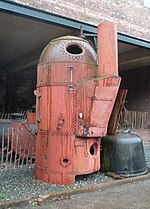
A vertical boiler with horizontal fire-tubes is a type of small vertical boiler, used to generate steam for small machinery. It is characterised by having many narrow fire-tubes, running horizontally.

Boilers like this have been widely used on ships as either auxiliary or donkey boilers.[i] Smaller examples, particularly the Robertson type have been used for steam wagons.
Parallel tube boilers edit
Parallel tube boilers place all of their fire-tubes in a single parallel group, running from side to side of the boiler shell. The best known of these is the Cochran design.
Cochran boiler edit
The Cochran boiler was produced by Cochran & Co. of Annan, Scotland.[2] It is widely used in marine practice, either fired directly by coal or oil fuels, or else used for heat recovery from the exhaust of large diesel engines.[3] Where such a boiler may be heated either by the exhaust gases of the main propulsion plant, or else separately fired when in port (usually by oil rather than coal) it is referred to as a composite boiler.[4]
The boiler is a cylindrical vertical water drum with a hemispherical domed top. This domed shape is strong enough not to require staying. The firebox is another hemispherical dome, riveted to the base foundation ring to give a narrow waterspace.
The fire-tubes are arranged in a single horizontal group above this, mounted between two flat vertical plates that are inset into the boiler barrel. The first of these plates forms a shallow combustion chamber and is connected to the firebox by a short diagonal neck. The combustion chamber is of the "dry back" form and is closed by a steel and firebrick plate, rather than a water jacket. The exhaust from the fire-tubes is into an external smokebox and a vertical flue. For maintenance access to the tubes, a manhole is provided in the hemispherical dome.
A typical Cochran boiler, as illustrated,[5] might be 15 feet (4.57 m) high and 7 feet (2.13 m) in diameter, giving a heating surface of 500 square feet (46.45 m2), and a grate area of 24 square feet (2.23 m2). Working pressure is between 100 and 125 psi (6.9 and 8.6 bar; 690 and 860 kPa).
Where composite firing is used,[4] there are several possible arrangements for the heating gases.[6] Most use a double-pass tube arrangement where another dry back combustion chamber routes the gases from one tube bank to return through the other. Some arrangements use a separate tube bank for the heat recovery exhaust gases or the direct firing gases, others pass the exhaust gases into the top of the (unlit) firebox. A pure heat-recovery boiler may have no firebox at all, other than a shallow domed plate for strength.[6]

Cochran also offer a modified "Sinuflo" fire-tube, which is claimed to offer better heat transfer from the gases. This is bent into a number of horizontal sinusoidal waves, rather than being straight.[6]
The Cochran boiler was not applied to locomotives, but was used for a pair of experimental steam railmotors built for the GNSR by Andrew Barclay in 1905.[7] These were not successful and were scrapped after a few years, although one coach body survives in a poor state.[8]
Clarke Chapman boiler edit

The Clarke Chapman boiler is similar to the Cochran type, with the difference that the top of the boiler shell is a shallow dome rather than a hemisphere. This dome shape is still sufficiently strong to withstand the pressure, but there is now a sharp corner between the shell and the top plate. This corner requires the support of gusset stays.
Clarke Chapman boilers are made in both 'dry back' (as for the Cochran) and 'wet back' forms.[9] The wet back or "Victoria"[10] (illustrated) has the combustion chamber entirely surrounded by water. This increases the heating surface and reduces lost heat, but it also makes the boiler more complex to manufacture and makes tube cleaning more difficult.
Radial horizontal tube boilers edit

Radial horizontal tube boilers avoid the flat tubeplate of the Cochran boiler in favour of a circular firebox, a shape that better resists pressure. They thus have their tubes arranged radially, so as to seat more easily by entering the firebox perpendicular to the plate.
Robertson boiler edit
The design by Robertson of Fleetwood, Lancashire, was originally used in steam wagons. It was often used in similar situations to the Sentinel boiler, but has fire-tubes rather than watertubes. It is best known from its popularity in model engineering, as a multi-tube boiler that's relatively easy to construct.
The boiler consists of two concentric drums with a waterspace between them. Fire-tubes pass through this drum, arranged symmetrically around the diameter. The entire boiler is wrapped in a cylindrical smokebox. The top of the inner drum is not water-jacketed and is only closed by a steel plate. The outer drum is a parallel cylinder but the inner drum is usually stepped in three diameters: wide around the fire grate to provide the most grate area and to promote rapid boiling in its waterjacket, the central section carries the inner ends of the fire-tubes, and the upper section is narrowed to reduce the unjacketed surface area and to provide an open steam space above the waterline.[9][11] This upper space is deliberately oversized so that when fitted to a road vehicle, any tilting during hill climbing will still leave an adequate depth of water cover above the tubes.
The top plate is unjacketed so that it may contain a hatch and a firing chute. Where the boiler is used for steam wagons it is often coke-fired with a deep firebed, and coke is merely poured down this chute rather than carefully distributed. This means of firing is acceptable with coke, but with coal would lead to a thick, dull fire that blocked with clinker. It is also less distracting when trying to drive a steam vehicle. Avoiding coal also reduces the risk of volatile gases flaring out of the firing chute when it is opened.
The boiler is sometimes superheated by a semi-radiant element arranged as a coil inside the upper part of the central drum.[11]
Other designs edit

Blake boiler edit
The Blake boiler has features of both the Clarke Chapman and the Robertson designs. The combustion chamber is set entirely within the water space so that all of it can provide heating surface, and it is made cylindrical for strength. The tubes are arranged radially rather than in a parallel group, so as to enter the combustion chamber perpendicularly. This makes expanding their ends a simpler operation and gives better sealing. The smokebox is larger and partially wraps around the outside of the boiler drum.[12]
Harris "Economic" boiler edit
The Harris "Economic" boiler[13] is a design for a model engineering-sized boiler. Similar to the Blake, but symmetrical with a centrally placed combustion chamber and fire-tubes around the entire circumference.
Riley Brothers edit
Similar boilers, both fire-tube to 'Meredith's Patent' and water-tube boilers of their own design, were also produced by Riley Brothers of Stockton-on-Tees from around 1890 to WWI.[14]
References edit
Vertical boilers with horizontal fire-tubes.
- ^ Milton & Marine Steam Boilers.
- ^ Cochran
- ^ Milton, J. H. (1961) [1953]. Marine Steam Boilers (2nd ed.). Newnes. pp. 63–66.
- ^ a b Milton & Marine Steam Boilers, pp. 119–121.
- ^ Bentley, Wallace (1918). Sketches of Engine and Machine Details. p. 106.
- ^ a b c Milton & Marine Steam Boilers, pp. 133–135.
- ^ Jenkinson, David (1996). "15: Alternatives to convention". The History of British Railway Carriages 1900–1953. Vol. I (2nd ed.). Pendragon. p. 266. ISBN 1-899816-03-8.
- ^ "GNSR Steam Railmotor Saloon (body only)". Vintage Carriages Trust.
- ^ a b Kennedy, Modern Engines, Vol III
- ^ Milton, James Tayler; Horner, Joseph Gregory (1911). . In Chisholm, Hugh (ed.). Encyclopædia Britannica. Vol. 04 (11th ed.). Cambridge University Press. pp. 141–153, see page 143, fig. 6.
- ^ a b Harris, K. N. (1974). Model Boilers and Boilermaking. MAP. pp. 52–53. ISBN 0-85242-377-2.
- ^ Kennedy, Rankin (1905). The Book of Modern Engines and Power Generators. Vol. VI. London: Caxton. p. 31.
- ^ Harris, Model Boilers, pp. 158-159
- ^ "Riley Brothers". Grace's Guide.