


Summary
An electric motor is an electrical machine that converts electrical energy into mechanical energy. Most electric motors operate through the interaction between the motor's magnetic field and electric current in a wire winding to generate force in the form of torque applied on the motor's shaft. An electric generator is mechanically identical to an electric motor, but operates in reverse, converting mechanical energy into electrical energy.
 Animation showing operation of a brushed DC electric motor | |
| Type | Passive |
|---|---|
| Working principle | Electromagnetism |
| Electronic symbol | |
 | |
Electric motors can be powered by direct current (DC) sources, such as from batteries or rectifiers, or by alternating current (AC) sources, such as a power grid, inverters or electrical generators.
Electric motors may be classified by considerations such as power source type, construction, application and type of motion output. They can be brushed or brushless, single-phase, two-phase, or three-phase, axial or radial flux, and may be air-cooled or liquid-cooled.
Standardized motors provide power for industrial use. The largest are used for ship propulsion, pipeline compression and pumped-storage applications, with output exceeding 100 megawatts.
Applications include industrial fans, blowers and pumps, machine tools, household appliances, power tools, vehicles, and disk drives. Small motors may be found in electric watches. In certain applications, such as in regenerative braking with traction motors, electric motors can be used in reverse as generators to recover energy that might otherwise be lost as heat and friction.
Electric motors produce linear or rotary force (torque) intended to propel some external mechanism. This makes them a type of actuator. They are generally designed for continuous rotation, or for linear movement over a significant distance compared to its size. Solenoids also convert electrical power to mechanical motion, but over only a limited distance.
History edit
Early motors edit

Before modern electromagnetic motors, experimental motors that worked by electrostatic force were investigated. The first electric motors were simple electrostatic devices described in experiments by Scottish monk Andrew Gordon and American experimenter Benjamin Franklin in the 1740s.[2][3] The theoretical principle behind them, Coulomb's law, was discovered but not published, by Henry Cavendish in 1771. This law was discovered independently by Charles-Augustin de Coulomb in 1785, who published it so that it is now known with his name.[4] Due to the difficulty of generating the high voltages they required, electrostatic motors were never used for practical purposes.
The invention of the electrochemical battery by Alessandro Volta in 1799[5] made possible the production of persistent electric currents. Hans Christian Ørsted discovered in 1820 that an electric current creates a magnetic field, which can exert a force on a magnet. It only took a few weeks for André-Marie Ampère to develop the first formulation of the electromagnetic interaction and present the Ampère's force law, that described the production of mechanical force by the interaction of an electric current and a magnetic field.[6]
The first demonstration of the effect with a rotary motion was given by Michael Faraday on 3 September 1821 in the basement of the Royal Institution.[7] A free-hanging wire was dipped into a pool of mercury, on which a permanent magnet (PM) was placed. When a current was passed through the wire, the wire rotated around the magnet, showing that the current gave rise to a close circular magnetic field around the wire.[8] Faraday published the results of his discovery in the Quarterly Journal of Science, and sent copies of his paper along with pocket-sized models of his device to colleagues around the world so they could also witness the phenomenon of electromagnetic rotations.[7] This motor is often demonstrated in physics experiments, substituting brine for (toxic) mercury. Barlow's wheel was an early refinement to this Faraday demonstration, although these and similar homopolar motors remained unsuited to practical application until late in the century.


In 1827, Hungarian physicist Ányos Jedlik started experimenting with electromagnetic coils. After Jedlik solved the technical problems of continuous rotation with the invention of the commutator, he called his early devices "electromagnetic self-rotors". Although they were used only for teaching, in 1828 Jedlik demonstrated the first device to contain the three main components of practical DC motors: the stator, rotor and commutator. The device employed no permanent magnets, as the magnetic fields of both the stationary and revolving components were produced solely by the currents flowing through their windings.[10][11][12][13][14][15][16]
DC motors edit
The first commutator DC electric motor capable of turning machinery was invented by English scientist William Sturgeon in 1832.[17] Following Sturgeon's work, a commutator-type direct-current electric motor was built by American inventor Thomas Davenport and Emily Davenport,[18] which he patented in 1837. The motors ran at up to 600 revolutions per minute, and powered machine tools and a printing press.[19] Due to the high cost of primary battery power, the motors were commercially unsuccessful and bankrupted Davenport. Several inventors followed Sturgeon in the development of DC motors, but all encountered the same battery cost issues. As no electricity distribution system was available at the time, no practical commercial market emerged for these motors.[20]
After many other more or less successful attempts with relatively weak rotating and reciprocating apparatus Prussian/Russian Moritz von Jacobi created the first real rotating electric motor in May 1834. It developed remarkable mechanical output power. His motor set a world record, which Jacobi improved four years later in September 1838.[21] His second motor was powerful enough to drive a boat with 14 people across a wide river. It was also in 1839/40 that other developers managed to build motors with similar and then higher performance.
In 1827–1828, Jedlik built a device using similar principles to those used in his electromagnetic self-rotors that was capable of useful work.[22][23][24][25][26][27][10][16] He built a model electric vehicle that same year.[28]
A major turning point came in 1864, when Antonio Pacinotti first described the ring armature (although initially conceived in a DC generator, i.e. a dynamo).[6] This featured symmetrically grouped coils closed upon themselves and connected to the bars of a commutator, the brushes of which delivered practically non-fluctuating current.[29][30] The first commercially successful DC motors followed the developments by Zénobe Gramme who, in 1871, reinvented Pacinotti's design and adopted some solutions by Werner Siemens.
A benefit to DC machines came from the discovery of the reversibility of the electric machine, which was announced by Siemens in 1867 and observed by Pacinotti in 1869.[6] Gramme accidentally demonstrated it on the occasion of the 1873 Vienna World's Fair, when he connected two such DC devices up to 2 km from each other, using one of them as a generator and the other as motor.[31]
The drum rotor was introduced by Friedrich von Hefner-Alteneck of Siemens & Halske to replace Pacinotti's ring armature in 1872, thus improving the machine efficiency.[6] The laminated rotor was introduced by Siemens & Halske the following year, achieving reduced iron losses and increased induced voltages. In 1880, Jonas Wenström provided the rotor with slots for housing the winding, further increasing the efficiency.
In 1886, Frank Julian Sprague invented the first practical DC motor, a non-sparking device that maintained relatively constant speed under variable loads. Other Sprague electric inventions about this time greatly improved grid electric distribution (prior work done while employed by Thomas Edison), allowed power from electric motors to be returned to the electric grid, provided for electric distribution to trolleys via overhead wires and the trolley pole, and provided control systems for electric operations. This allowed Sprague to use electric motors to invent the first electric trolley system in 1887–88 in Richmond, Virginia, the electric elevator and control system in 1892, and the electric subway with independently powered centrally-controlled cars. The latter were first installed in 1892 in Chicago by the South Side Elevated Railroad, where it became popularly known as the "L". Sprague's motor and related inventions led to an explosion of interest and use in electric motors for industry. The development of electric motors of acceptable efficiency was delayed for several decades by failure to recognize the extreme importance of an air gap between the rotor and stator. Efficient designs have a comparatively small air gap.[32][a] The St. Louis motor, long used in classrooms to illustrate motor principles, is inefficient for the same reason, as well as appearing nothing like a modern motor.[34]
Electric motors revolutionized industry. Industrial processes were no longer limited by power transmission using line shafts, belts, compressed air or hydraulic pressure. Instead, every machine could be equipped with its own power source, providing easy control at the point of use, and improving power transmission efficiency. Electric motors applied in agriculture eliminated human and animal muscle power from such tasks as handling grain or pumping water. Household uses (like in washing machines, dishwashers, fans, air conditioners and refrigerators (replacing ice boxes) of electric motors reduced heavy labor in the home and made higher standards of convenience, comfort and safety possible. Today, electric motors consume more than half of the electric energy produced in the US.[35]
AC motors edit
In 1824, French physicist François Arago formulated the existence of rotating magnetic fields, termed Arago's rotations, which, by manually turning switches on and off, Walter Baily demonstrated in 1879 as in effect the first primitive induction motor.[36][37][38][39] In the 1880s many inventors were trying to develop workable AC motors[40] because AC's advantages in long-distance high-voltage transmission were offset by the inability to operate motors on AC.
The first alternating-current commutatorless induction motor was invented by Galileo Ferraris in 1885. Ferraris was able to improve his first design by producing more advanced setups in 1886.[41] In 1888, the Royal Academy of Science of Turin published Ferraris's research detailing the foundations of motor operation, while concluding at that time that "the apparatus based on that principle could not be of any commercial importance as motor."[39][42][43]
Possible industrial development was envisioned by Nikola Tesla, who invented independently his induction motor in 1887 and obtained a patent in May 1888. In the same year, Tesla presented his paper A New System of Alternate Current Motors and Transformers to the AIEE that described three patented two-phase four-stator-pole motor types: one with a four-pole rotor forming a non-self-starting reluctance motor, another with a wound rotor forming a self-starting induction motor, and the third a true synchronous motor with separately excited DC supply to rotor winding. One of the patents Tesla filed in 1887, however, also described a shorted-winding-rotor induction motor. George Westinghouse, who had already acquired rights from Ferraris (US$1,000), promptly bought Tesla's patents (US$60,000 plus US$2.50 per sold hp, paid until 1897),[41] employed Tesla to develop his motors, and assigned C.F. Scott to help Tesla; however, Tesla left for other pursuits in 1889.[44][45][46][47] The constant speed AC induction motor was found not to be suitable for street cars,[40] but Westinghouse engineers successfully adapted it to power a mining operation in Telluride, Colorado in 1891.[48][49][50] Westinghouse achieved its first practical induction motor in 1892 and developed a line of polyphase 60 hertz induction motors in 1893, but these early Westinghouse motors were two-phase motors with wound rotors. B.G. Lamme later developed a rotating bar winding rotor.[44]
Steadfast in his promotion of three-phase development, Mikhail Dolivo-Dobrovolsky invented the three-phase induction motor in 1889, of both types cage-rotor and wound rotor with a starting rheostat, and the three-limb transformer in 1890. After an agreement between AEG and Maschinenfabrik Oerlikon, Doliwo-Dobrowolski and Charles Eugene Lancelot Brown developed larger models, namely a 20-hp squirrel cage and a 100-hp wound rotor with a starting rheostat. These were the first three-phase asynchronous motors suitable for practical operation.[41] Since 1889, similar developments of three-phase machinery were started Wenström. At the 1891 Frankfurt International Electrotechnical Exhibition, the first long distance three-phase system was successfully presented. It was rated 15 kV and extended over 175 km from the Lauffen waterfall on the Neckar river. The Lauffen power station included a 240 kW 86 V 40 Hz alternator and a step-up transformer while at the exhibition a step-down transformer fed a 100-hp three-phase induction motor that powered an artificial waterfall, representing the transfer of the original power source.[41] The three-phase induction is now used for the vast majority of commercial applications.[51][52] Mikhail Dolivo-Dobrovolsky claimed that Tesla's motor was not practical because of two-phase pulsations, which prompted him to persist in his three-phase work.[53]
The General Electric Company began developing three-phase induction motors in 1891.[44] By 1896, General Electric and Westinghouse signed a cross-licensing agreement for the bar-winding-rotor design, later called the squirrel-cage rotor.[44] Induction motor improvements flowing from these inventions and innovations were such that a 100-horsepower induction motor currently has the same mounting dimensions as a 7.5-horsepower motor in 1897.[44]
Twenty-first century edit
In 2022, electric motor sales were estimated to be 800 million units, increasing by 10% annually. Electric motors consume ≈50% of the world's electricity.[54] Since the 1980s, the market share of DC motors has declined in favor of AC motors.[55]: 89 [clarification needed]
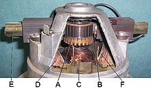
Components edit

An electric motor has two mechanical parts: the rotor, which moves, and the stator, which does not. Electrically, the motor consists of two parts, the field magnets and the armature, one of which is attached to the rotor and the other to the stator. Together they form a magnetic circuit.[56] The magnets create a magnetic field that passes through the armature. These can be electromagnets or permanent magnets. The field magnet is usually on the stator and the armature on the rotor, but these may be reversed.

Rotor edit
The rotor is the moving part that delivers the mechanical power. The rotor typically holds conductors that carry currents, on which the magnetic field of the stator exerts force to turn the shaft. Some rotors carry permanent magnets. Permanent magnets offer high efficiency over a large operating speed and power range.[57]
Stator edit
The stator surrounds the rotor, and usually holds field magnets, which are either electromagnets (wire windings around a ferromagnetic iron core) or permanent magnets. These create a magnetic field that passes through the rotor armature, exerting force on the rotor windings. The stator core is made up of many thin metal sheets that are insulated from each other, called laminations. These laminations are made of electrical steel, which has a specified magnetic permeability, hysteresis, and saturation. Laminations reduce losses that would result from induced circulating eddy currents that would flow if a solid core were used. Mains powered AC motors typically immobilize the wires within the windings by impregnating them with varnish in a vacuum. This prevents the wires in the winding from vibrating against each other which would abrade the wire insulation and cause premature failures. Resin-packed motors, used in deep well submersible pumps, washing machines, and air conditioners, encapsulate the stator in plastic resin to prevent corrosion and/or reduce conducted noise.[58]
Gap edit
An air gap between the stator and rotor allows it to turn. The width of the gap has a significant effect on the motor's electrical characteristics. It is generally made as small as possible, as a large gap weakens performance. Conversely, gaps that are too small may create friction in addition to noise.
Armature edit
The armature consists of wire windings on a ferromagnetic core. Electric current passing through the wire causes the magnetic field to exert a force (Lorentz force) on it, turning the rotor. Windings are coiled wires, wrapped around a laminated, soft, iron, ferromagnetic core so as to form magnetic poles when energized with current.
Electric machines come in salient- and nonsalient-pole configurations. In a salient-pole motor the rotor and stator ferromagnetic cores have projections called poles that face each other. Wire is wound around each pole below the pole face, which become north or south poles when current flows through the wire. In a nonsalient-pole (distributed field or round-rotor) motor, the ferromagnetic core is a smooth cylinder, with the windings distributed evenly in slots around the circumference. Supplying alternating current in the windings creates poles in the core that rotate continuously.[59] A shaded-pole motor has a winding around part of the pole that delays the phase of the magnetic field for that pole.
Commutator edit
A commutator is a rotary electrical switch that supplies current to the rotor. It periodically reverses the flow of current in the rotor windings as the shaft rotates. It consists of a cylinder composed of multiple metal contact segments on the armature. Two or more electrical contacts called "brushes" made of a soft conductive material like carbon press against the commutator. The brushes make sliding contact with successive commutator segments as the rotator turns, supplying current to the rotor. The windings on the rotor are connected to the commutator segments. The commutator reverses the current direction in the rotor windings with each half turn (180°), so the torque applied to the rotor is always in the same direction.[60] Without this reversal, the direction of torque on each rotor winding would reverse with each half turn, stopping the rotor. Commutated motors have been mostly replaced by brushless motors, permanent magnet motors, and induction motors.
Shaft edit
The motor shaft extends outside of the motor, where it satisfies the load. Because the forces of the load are exerted beyond the outermost bearing, the load is said to be overhung.[61]
Bearings edit
The rotor is supported by bearings, which allow the rotor to turn on its axis by transferring the force of axial and radial loads from the shaft to the motor housing.[61]
Inputs edit
Power supply edit
A DC motor is usually supplied through a split ring commutator as described above.
AC motors' commutation can be achieved using either a slip ring commutator or external commutation. It can be fixed-speed or variable-speed control type, and can be synchronous or asynchronous. Universal motors can run on either AC or DC.
Control edit
DC motors can be operated at variable speeds by adjusting the voltage applied to the terminals or by using pulse-width modulation (PWM).
AC motors operated at a fixed speed are generally powered directly from the grid or through motor soft starters.
AC motors operated at variable speeds are powered with various power inverter, variable-frequency drive or electronic commutator technologies.
The term electronic commutator is usually associated with self-commutated brushless DC motor and switched reluctance motor applications.
Types edit
Electric motors operate on one of three physical principles: magnetism, electrostatics and piezoelectricity.
In magnetic motors, magnetic fields are formed in both the rotor and the stator. The product between these two fields gives rise to a force and thus a torque on the motor shaft. One or both of these fields changes as the rotor turns. This is done by switching the poles on and off at the right time, or varying the strength of the pole.
Motors operate on either DC or AC current (or either).[62]
AC motors can be either asynchronous or synchronous.[63] Synchronous motors require the rotor to turn at the same speed as the stator's rotating field. Asynchronous rotors relax this constraint.
A fractional-horsepower motor either has a rating below about 1 horsepower (0.746 kW), or is manufactured with a frame size smaller than a standard 1 HP motor. Many household and industrial motors are in the fractional-horsepower class.
| Self-commutated | Externally commutated | |||
|---|---|---|---|---|
| Mechanical commutator | Electronic commutator[70][b] | Asynchronous | Synchronous2 | |
| AC[72][c] | DC | AC5, 6 | AC6 | |
| Electrically
excited:
PM |
PM rotor:
Ferromagnetic rotor: |
Three-phase:
Two-phase (condenser) Single-phase:
|
WRSM, PMSM or BLAC:[70]
Hysteresis Hybrid:
| |
| Simple electronics | Rectifier,
linear transistor(s) or DC chopper |
More elaborate
electronics |
Most elaborate
electronics (VFD), when provided | |
Notes:
1. Rotation is independent of the frequency of the AC voltage.
2. Rotation is equal to synchronous speed (motor-stator-field speed).
3. In SCIM, fixed-speed operation rotation is equal to synchronous speed, less slip speed.
4. In non-slip energy-recovery systems, WRIM is usually used for motor-starting but can be used to vary load speed.
5. Variable-speed operation.
6. Whereas induction- and synchronous-motor drives are typically with either six-step or sinusoidal-waveform output, BLDC-motor drives are usually with trapezoidal-current waveform; the behavior of both sinusoidal and trapezoidal PM machines is, however, identical in terms of their fundamental aspects.[74]
7. In variable-speed operation, WRIM is used in slip-energy recovery and double-fed induction-machine applications.
8. A cage winding is a short-circuited squirrel-cage rotor, a wound winding is connected externally through slip rings.
9. Mostly single-phase with some three-phase.
Abbreviations:
- BLAC – Brushless AC
- BLDC – Brushless DC
- BLDM – Brushless DC motor
- EC – Electronic commutator
- PM – Permanent magnet
- IPMSM – Interior permanent-magnet synchronous motor
- PMSM – Permanent magnet synchronous motor
- SPMSM – Surface permanent magnet synchronous motor
- SCIM – Squirrel-cage induction motor
- SRM – Switched reluctance motor
- SyRM – Synchronous reluctance motor
- VFD – Variable-frequency drive
- WRIM – Wound-rotor induction motor
- WRSM – Wound-rotor synchronous motor
- LRA – Locked-rotor amps: The current you can expect under starting conditions when you apply full voltage. It occurs instantly during start-up.
- RLA – Rated-load amps: The maximum current a motor should draw under any operating conditions. Often mistakenly called running-load amps, which leads people to believe, incorrectly, that the motor should always pull these amps.
- FLA – Full-load amps: Changed in 1976 to "RLA – rated-load amps".
Self-commutated motor edit
Brushed DC motor edit
Most DC motors are small permanent magnet (PM) types. They contain a brushed internal mechanical commutation to reverse motor windings' current in synchronism with rotation.[75]
Electrically excited DC motor edit

A commutated DC motor has a set of rotating windings wound on an armature mounted on a rotating shaft. The shaft also carries the commutator. Thus, every brushed DC motor has AC flowing through its windings. Current flows through one or more pairs of brushes that touch the commutator; the brushes connect an external source of electric power to the rotating armature.
The rotating armature consists of one or more wire coils wound around a laminated, magnetically "soft" ferromagnetic core. Current from the brushes flows through the commutator and one winding of the armature, making it a temporary magnet (an electromagnet). The magnetic field produced interacts with a stationary magnetic field produced by either PMs or another winding (a field coil), as part of the motor frame. The force between the two magnetic fields rotates the shaft. The commutator switches power to the coils as the rotor turns, keeping the poles from ever fully aligning with the magnetic poles of the stator field, so that the rotor keeps turning as long as power is applied.
Many of the limitations of the classic commutator DC motor are due to the need for brushes to maintain contact with the commutator, creating friction. The brushes create sparks while crossing the insulating gaps between commutator sections. Depending on the commutator design, the brushes may create short circuits between adjacent sections—and hence coil ends. Furthermore, the rotor coils' inductance causes the voltage across each to rise when its circuit opens, increasing the sparking. This sparking limits the maximum speed of the machine, as too-rapid sparking will overheat, erode, or even melt the commutator. The current density per unit area of the brushes, in combination with their resistivity, limits the motor's output. Crossing the gaps also generates electrical noise; sparking generates RFI. Brushes eventually wear out and require replacement, and the commutator itself is subject to wear and maintenance or replacement. The commutator assembly on a large motor is a costly element, requiring precision assembly of many parts. On small motors, the commutator is usually permanently integrated into the rotor, so replacing it usually requires replacing the rotor.
While most commutators are cylindrical, some are flat, segmented discs mounted on an insulator.
Large brushes create a large contact area, which maximizes motor output, while small brushes have low mass to maximize the speed at which the motor can run without excessive sparking. (Small brushes are desirable for their lower cost.) Stiffer brush springs can be used to make brushes of a given mass work at a higher speed, despite greater friction losses (lower efficiency) and accelerated brush and commutator wear. Therefore, DC motor brush design entails a trade-off between output power, speed, and efficiency/wear.
DC machines are defined as follows:[76]
- Armature circuit – A winding that carries the load, either stationary or rotating.
- Field circuit – A set of windings that produces a magnetic field.
- Commutation: A mechanical technique in which rectification can be achieved, or from which DC can be derived.

The five types of brushed DC motor are:
- Shunt-wound
- Series-wound
- Compound (two configurations):
- Cumulative compound
- Differentially compounded
- Permanent magnet (not shown)
- Separately excited (not shown).
Permanent magnet edit
A permanent magnet (PM) motor does not have a field winding on the stator frame, relying instead on PMs to provide the magnetic field. Compensating windings in series with the armature may be used on large motors to improve commutation under load. This field is fixed and cannot be adjusted for speed control. PM fields (stators) are convenient in miniature motors to eliminate the power consumption of the field winding. Most larger DC motors are of the "dynamo" type, which have stator windings. Historically, PMs could not be made to retain high flux if they were disassembled; field windings were more practical to obtain the needed flux. However, large PMs are costly, as well as dangerous and difficult to assemble; this favors wound fields for large machines.
To minimize overall weight and size, miniature PM motors may use high energy magnets made with neodymium; most are neodymium-iron-boron alloy. With their higher flux density, electric machines with high-energy PMs are at least competitive with all optimally designed singly-fed synchronous and induction electric machines. Miniature motors resemble the structure in the illustration, except that they have at least three rotor poles (to ensure starting, regardless of rotor position) and their outer housing is a steel tube that magnetically links the exteriors of the curved field magnets.
Electronic commutator (EC) edit
Brushless DC edit
Some of the problems of the brushed DC motor are eliminated in the BLDC design. In this motor, the mechanical "rotating switch" or commutator is replaced by an external electronic switch synchronised to the rotor's position. BLDC motors are typically 85%+ efficient, reaching up to 96.5%,[77] while brushed DC motors are typically 75–80% efficient.
The BLDC motor's characteristic trapezoidal counter-electromotive force (CEMF) waveform is derived partly from the stator windings being evenly distributed, and partly from the placement of the rotor's permanent magnets. Also known as electronically commutated DC or inside-out DC motors, the stator windings of trapezoidal BLDC motors can be single-phase, two-phase or three-phase and use Hall effect sensors mounted on their windings for rotor position sensing and low cost closed-loop commutator control.
BLDC motors are commonly used where precise speed control is necessary, as in computer disk drives or video cassette recorders. The spindles within CD, CD-ROM (etc.) drives, and mechanisms within office products, such as fans, laser printers and photocopiers. They have several advantages over conventional motors:
- They are more efficient than AC fans using shaded-pole motors, running much cooler than the AC equivalents. This cool operation leads to much-improved life of the fan's bearings.
- Without a commutator, the life of a BLDC motor can be significantly longer compared to a brushed DC motor with a commutator. Commutation tends to cause electrical and RF noise; without a commutator or brushes, a BLDC motor may be used in electrically sensitive devices like audio equipment or computers.
- The same Hall effect sensors that provide the commutation can provide a convenient tachometer signal for closed-loop control (servo-controlled) applications. In fans, the tachometer signal can be used to derive a "fan OK" signal as well as provide running speed feedback.
- The motor can be synchronized to an internal or external clock, providing precise speed control.
- BLDC motors do not spark, making them better suited to environments with volatile chemicals and fuels. Sparking also generates ozone, which can accumulate in poorly ventilated buildings.
- BLDC motors are usually used in small equipment such as computers and are generally used in fans to remove heat.
- They make little noise, which is an advantage in equipment that is affected by vibrations.
Modern BLDC motors range in power from a fraction of a watt to many kilowatts. Larger BLDC motors rated up to about 100 kW are used in electric vehicles. They also find use in electric model aircraft.
Switched reluctance motor edit

The switched reluctance motor (SRM) has no brushes or permanent magnets, and the rotor has no electric currents. Torque comes from a slight misalignment of poles on the rotor with poles on the stator. The rotor aligns itself with the magnetic field of the stator, while the stator field windings are sequentially energized to rotate the stator field.
The magnetic flux created by the field windings follows the path of least magnetic sending the flux through rotor poles that are closest to the energized poles of the stator, thereby magnetizing those poles of the rotor and creating torque. As the rotor turns, different windings are energized, keeping the rotor turning.
SRMs are used in some appliances[78] and vehicles.[79]
Universal AC/DC motor edit

A commutated, electrically excited, series or parallel wound motor is referred to as a universal motor because it can be designed to operate on either AC or DC power. A universal motor can operate well on AC because the current in both the field and the armature coils (and hence the resultant magnetic fields) synchronously reverse polarity, and hence the resulting mechanical force occurs in a constant direction of rotation.
Operating at normal power line frequencies, universal motors are often used in sub-kilowatt applications. Universal motors formed the basis of the traditional railway traction motor in electric railways. In this application, using AC power on a motor designed to run on DC would experience efficiency losses due to eddy current heating of their magnetic components, particularly the motor field pole-pieces that, for DC, would have used solid (un-laminated) iron. They are now rarely used.
An advantage is that AC power may be used on motors that specifically have high starting torque and compact design if high running speeds are used. By contrast, maintenance is higher and lifetimes are shortened. Such motors are used in devices that are not heavily used, and have high starting-torque demands. Multiple taps on the field coil provide (imprecise) stepped speed control. Household blenders that advertise many speeds typically combine a field coil with several taps and a diode that can be inserted in series with the motor (causing the motor to run on half-wave rectified AC). Universal motors also lend themselves to electronic speed control and, as such, are a choice for devices such as domestic washing machines. The motor can agitate the drum (both forwards and in reverse) by switching the field winding with respect to the armature.
Whereas SCIMs cannot turn a shaft faster than allowed by the power line frequency, universal motors can run at much higher speeds. This makes them useful for appliances such as blenders, vacuum cleaners, and hair dryers where high speed and light weight are desirable. They are also commonly used in portable power tools, such as drills, sanders, circular and jig saws, where the motor's characteristics work well. Many vacuum cleaner and weed trimmer motors exceed 10,000 rpm, while miniature grinders may exceed 30,000 rpm.
Externally commutated AC machine edit
AC induction and synchronous motors are optimized for operation on single-phase or polyphase sinusoidal or quasi-sinusoidal waveform power such as supplied for fixed-speed applications by the AC power grid or for variable-speed application from variable-frequency drive (VFD) controllers.
Induction motor edit
An induction motor is an asynchronous AC motor where power is transferred to the rotor by electromagnetic induction, much like transformer action. An induction motor resembles a rotating transformer, because the stator (stationary part) is essentially the primary side of the transformer and the rotor (rotating part) is the secondary side. Polyphase induction motors are widely used in industry.

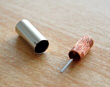
Cage and wound rotor edit
Induction motors may be divided into Squirrel Cage Induction Motors (SCIM) and Wound Rotor Induction Motors (WRIM). SCIMs have a heavy winding made up of solid bars, usually aluminum or copper, electrically connected by rings at the ends of the rotor. The bars and rings as a whole are much like an animal's rotating exercise cage.
Currents induced into this winding provide the rotor magnetic field. The shape of the rotor bars determines the speed-torque characteristics. At low speeds, the current induced in the squirrel cage is nearly at line frequency and tends to stay in the outer parts of the cage. As the motor accelerates, the slip frequency becomes lower, and more current reaches the interior. By shaping the bars to change the resistance of the winding portions in the interior and outer parts of the cage, a variable resistance is effectively inserted in the rotor circuit. However, most such motors employ uniform bars.
In a WRIM, the rotor winding is made of many turns of insulated wire and is connected to slip rings on the motor shaft. An external resistor or other control device can be connected in the rotor circuit. Resistors allow control of the motor speed, although dissipating significant power. A converter can be fed from the rotor circuit and return the slip-frequency power that would otherwise be wasted into the power system through an inverter or separate motor-generator.
WRIMs are used primarily to start a high inertia load or a load that requires high starting torque across the full speed range. By correctly selecting the resistors used in the secondary resistance or slip ring starter, the motor is able to produce maximum torque at a relatively low supply current from zero speed to full speed.
Motor speed can be changed because the motor's torque curve is effectively modified by the amount of resistance connected to the rotor circuit. Increasing resistance lowers the speed of maximum torque. If the resistance is increased beyond the point where the maximum torque occurs at zero speed, the torque is further reduced.
When used with a load that has a torque curve that increases with speed, the motor operates at the speed where the torque developed by the motor is equal to the load torque. Reducing the load causes the motor to speed up, while increasing the load causes the motor to slow down until the load and motor torque are again equal. Operated in this manner, the slip losses are dissipated in the secondary resistors and can be significant. The speed regulation and net efficiency is poor.
Torque motor edit
A torque motor can operate indefinitely while stalled, that is, with the rotor blocked from turning, without incurring damage. In this mode of operation, the motor applies a steady torque to the load.
A common application is the supply- and take-up reel motors in a tape drive. In this application, driven by a low voltage, the characteristics of these motors apply a steady light tension to the tape whether or not the capstan is feeding tape past the tape heads. Driven from a higher voltage (delivering a higher torque), torque motors can achieve fast-forward and rewind operation without requiring additional mechanics such as gears or clutches. In the computer gaming world, torque motors are used in force feedback steering wheels.
Another common application is to control the throttle of an internal combustion engine with an electronic governor. The motor works against a return spring to move the throttle in accord with the governor output. The latter monitors engine speed by counting electrical pulses from the ignition system or from a magnetic pickup and depending on the speed, makes small adjustments to the amount of current. If the engine slows down relative to the desired speed, the current increases, producing more torque, pulling against the return spring and opening the throttle. Should the engine run too fast, the governor reduces the current, allowing the return spring to pull back and reduce the throttle.
Synchronous motor edit
A synchronous electric motor is an AC motor. It includes a rotor spinning with coils passing magnets at the same frequency as the AC and produces a magnetic field to drive it. It has zero slip under typical operating conditions. By contrast induction motors must slip to produce torque. One type of synchronous motor is like an induction motor except that the rotor is excited by a DC field. Slip rings and brushes conduct current to the rotor. The rotor poles connect to each other and move at the same speed. Another type, for low load torque, has flats ground onto a conventional squirrel-cage rotor to create discrete poles. Yet another, as made by Hammond for its pre-World War II clocks, and in older Hammond organs, has no rotor windings and discrete poles. It is not self-starting. The clock requires manual starting by a small knob on the back, while the older Hammond organs had an auxiliary starting motor connected by a spring-loaded manually operated switch.
Hysteresis synchronous motors typically are (essentially) two-phase motors with a phase-shifting capacitor for one phase. They start like induction motors, but when slip rate decreases sufficiently, the rotor (a smooth cylinder) becomes temporarily magnetized. Its distributed poles make it act like a permanent magnet synchronous motor. The rotor material, like that of a common nail, stays magnetized, but can be demagnetized with little difficulty. Once running, the rotor poles stay in place; they do not drift.
Low-power synchronous timing motors (such as those for traditional electric clocks) may have multi-pole permanent magnet external cup rotors, and use shading coils to provide starting torque. Telechron clock motors have shaded poles for starting torque, and a two-spoke ring rotor that performs like a discrete two-pole rotor.
Doubly-fed electric machine edit
Doubly fed electric motors have two independent multiphase winding sets, which contribute active (i.e., working) power to the energy conversion process, with at least one of the winding sets electronically controlled for variable speed operation. Two independent multiphase winding sets (i.e., dual armature) are the maximum provided in a single package without topology duplication. Doubly-fed electric motors have an effective constant torque speed range that is twice synchronous speed for a given frequency of excitation. This is twice the constant torque speed range as singly-fed electric machines, which have only one active winding set.
A doubly-fed motor allows for a smaller electronic converter but the cost of the rotor winding and slip rings may offset the saving in the power electronics components. Difficulties affect controlling speed near synchronous speed limit applications.[80]
Advanced types edit
Rotary edit
Ironless or coreless rotor motor edit
The coreless or ironless DC motor is a specialized permanent magnet DC motor.[75] Optimized for rapid acceleration, the rotor is constructed without an iron core. The rotor can take the form of a winding-filled cylinder, or a self-supporting structure comprising only wire and bonding material. The rotor can fit inside the stator magnets; a magnetically soft stationary cylinder inside the rotor provides a return path for the stator magnetic flux. A second arrangement has the rotor winding basket surrounding the stator magnets. In that design, the rotor fits inside a magnetically soft cylinder that can serve as the motor housing, and provides a return path for the flux.
Because the rotor is much lower mass than a conventional rotor, it can accelerate much more rapidly, often achieving a mechanical time constant under one millisecond. This is especially true if the windings use aluminum rather than (heavier) copper. The rotor has no metal mass to act as a heat sink; even small motors must be cooled. Overheating can be an issue for these designs.
The vibrating alert of cellular phones can be generated by cylindrical permanent-magnet motors, or disc-shaped types that have a thin multipolar disc field magnet, and an intentionally unbalanced molded-plastic rotor structure with two bonded coreless coils. Metal brushes and a flat commutator switch power to the rotor coils.
Related limited-travel actuators have no core and a bonded coil placed between the poles of high-flux thin permanent magnets. These are the fast head positioners for rigid-disk ("hard disk") drives. Although the contemporary design differs considerably from that of loudspeakers, it is still loosely (and incorrectly) referred to as a "voice coil" structure, because some earlier rigid-disk-drive heads moved in straight lines, and had a drive structure much like that of a loudspeaker.
Pancake or axial rotor motor edit
The printed armature or pancake motor has windings shaped as a disc running between arrays of high-flux magnets. The magnets are arranged in a circle facing the rotor spaced to form an axial air gap.[81] This design is commonly known as the pancake motor because of its flat profile.
The armature (originally formed on a printed circuit board) is made from punched copper sheets that are laminated together using advanced composites to form a thin, rigid disc. The armature does not have a separate ring commutator. The brushes move directly on the armature surface making the whole design compact.
An alternative design is to use wound copper wire laid flat with a central conventional commutator, in a flower and petal shape. The windings are typically stabilized with electrical epoxy potting systems. These are filled epoxies that have moderate, mixed viscosity and a long gel time. They are highlighted by low shrinkage and low exotherm, and are typically UL 1446 recognized as a potting compound insulated with 180 °C (356 °F), Class H rating.
The unique advantage of ironless DC motors is the absence of cogging (torque variations caused by changing attraction between the iron and the magnets). Parasitic eddy currents cannot form in the rotor as it is totally ironless, although iron rotors are laminated. This can greatly improve efficiency, but variable-speed controllers must use a higher switching rate (>40 kHz) or DC because of decreased electromagnetic induction.
These motors were invented to drive the capstan(s) of magnetic tape drives, where minimal time to reach operating speed and minimal stopping distance were critical. Pancake motors are widely used in high-performance servo-controlled systems, robotic systems, industrial automation and medical devices. Due to the variety of constructions now available, the technology is used in applications from high temperature military to low cost pump and basic servos.
Another approach (Magnax) is to use a single stator sandwiched between two rotors. One such design has produced peak power of 15 kW/kg, sustained power around 7.5 kW/kg. This yokeless axial flux motor offers a shorter flux path, keeping the magnets further from the axis. The design allows zero winding overhang; 100 percent of the windings are active. This is enhanced with the use of rectangular-crosssection copper wire. The motors can be stacked to work in parallel. Instabilities are minimized by ensuring that the two rotor discs put equal and opposing forces onto the stator disc. The rotors are connected directly to one another via a shaft ring, cancelling out the magnetic forces.[82]
Servomotor edit
A servomotor is a motor that is used within a position-control or speed-control feedback system. Servomotors are used in applications such as machine tools, pen plotters, and other process systems. Motors intended for use in a servomechanism must have predictable characteristics for speed, torque, and power. The speed/torque curve is important and is high ratio for a servomotor. Dynamic response characteristics such as winding inductance and rotor inertia are important; these factors limit performance. Large, powerful, but slow-responding servo loops may use conventional AC or DC motors and drive systems with position or speed feedback. As dynamic response requirements increase, more specialized motor designs such as coreless motors are used. AC motors' superior power density and acceleration characteristics tends to favor permanent magnet synchronous, BLDC, induction, and SRM drive approaches.[81]
A servo system differs from some stepper motor applications in that position feedback is continuous while the motor is running. A stepper system inherently operates open-loop—relying on the motor not to "miss steps" for short term accuracy—with any feedback such as a "home" switch or position encoder external to the motor system.[83]
Stepper motor edit

Stepper motors are typically used to provide precise rotations. An internal rotor containing permanent magnets or a magnetically soft rotor with salient poles is controlled by a set of electronically switched external magnets. A stepper motor may also be thought of as a cross between a DC electric motor and a rotary solenoid. As each coil is energized in turn, the rotor aligns itself with the magnetic field produced by the energized field winding. Unlike a synchronous motor, the stepper motor may not rotate continuously; instead, it moves in steps—starting and then stopping—advancing from one position to the next as field windings are energized and de-energized in sequence. Depending on the sequence, the rotor may turn forwards or backwards, and it may change direction, stop, speed up or slow down at any time.
Simple stepper motor drivers entirely energize or entirely de-energize the field windings, leading the rotor to "cog" to a limited number of positions. Microstepping drivers can proportionally control the power to the field windings, allowing the rotors to position between cog points and rotate smoothly. Computer-controlled stepper motors are one of the most versatile positioning systems, particularly as part of a digital servo-controlled system.
Stepper motors can be rotated to a specific angle in discrete steps with ease, and hence stepper motors are used for read/write head positioning in early disk drives, where the precision and speed they offered could correctly position the read/write head. As drive density increased, precision and speed limitations made them obsolete for hard drives—the precision limitation made them unusable, and the speed limitation made them uncompetitive—thus newer hard disk drives use voice coil-based head actuator systems. (The term "voice coil" in this connection is historic; it refers to the structure in a cone-type loudspeaker.)
Stepper motors are often used in computer printers, optical scanners, and digital photocopiers to move the active element, the print head carriage (inkjet printers), and the platen or feed rollers.
So-called quartz analog wristwatches contain the smallest commonplace stepping motors; they have one coil, draw little power, and have a permanent magnet rotor. The same kind of motor drives battery-powered quartz clocks. Some of these watches, such as chronographs, contain more than one stepper motor.
Closely related in design to three-phase AC synchronous motors, stepper motors and SRMs are classified as variable reluctance motor type.[84]
Linear edit
A linear motor is essentially any electric motor that has been "unrolled" so that, instead of producing torque (rotation), it produces a straight-line force along its length.
Linear motors are most commonly induction motors or stepper motors. Linear motors are commonly found in roller-coasters where the rapid motion of the motorless railcar is controlled by the rail. They are also used in maglev trains, where the train "flies" over the ground. On a smaller scale, the 1978 era HP 7225A pen plotter used two linear stepper motors to move the pen along the X and Y axes.[85]
Non-magnetic edit
Electrostatic edit
An electrostatic motor is based on the attraction and repulsion of electric charge. Usually, electrostatic motors are the dual of conventional coil-based motors. They typically require a high-voltage power supply, although small motors employ lower voltages. Conventional electric motors instead employ magnetic attraction and repulsion, and require high current at low voltages. In the 1750s, the first electrostatic motors were developed by Benjamin Franklin and Andrew Gordon. Electrostatic motors find frequent use in micro-electro-mechanical systems (MEMS) where their drive voltages are below 100 volts, and where moving, charged plates are far easier to fabricate than coils and iron cores. The molecular machinery that runs living cells is often based on linear and rotary electrostatic motors.[citation needed]
Piezoelectric edit
A piezoelectric motor or piezo motor is a type of electric motor based upon the change in shape of a piezoelectric material when an electric field is applied. Piezoelectric motors make use of the converse piezoelectric effect whereby the material produces acoustic or ultrasonic vibrations to produce linear or rotary motion.[86] In one mechanism, the elongation in a single plane is used to make a series of stretches and position holds, similar to the way a caterpillar moves.[87]
Electric propulsion edit
An electrically powered spacecraft propulsion system uses electric motor technology to propel spacecraft in outer space. Most systems are based on electrically accelerating propellant to high speed, while some systems are based on electrodynamic tethers principles of propulsion to the magnetosphere.[88]
Comparison by major categories edit
| Type | Advantages | Disadvantages | Typical application | Typical drive, output |
|---|---|---|---|---|
| Self-commutated motors | ||||
| Brushed DC | Simple speed control
Low initial cost |
Maintenance (brushes)
Medium lifespan Costly commutator and brushes |
Steel mills
Paper making machines Treadmill exercisers Automotive accessories |
Rectifier, linear transistor(s) or DC chopper controller.[89] |
| Brushless DC motor (BLDC or BLDM) | Long lifespan
Low maintenance High efficiency |
Higher initial cost
Requires EC controller with closed-loop control |
Rigid ("hard") disk drives
CD/DVD players Electric vehicles RC Vehicles UAVs |
Synchronous; single-phase or three-phase with PM rotor and trapezoidal stator winding; VFD typically VS PWM inverter type.[81][90][91] |
| Switched reluctance motor (SRM) | Long lifespan
Low maintenance High efficiency No permanent magnets Low cost Simple construction |
Mechanical resonance
possible High iron losses Not possible: * Open or vector control * Parallel operation Requires EC controller[84] |
Appliances
Electric Vehicles Textile mills Aircraft applications |
PWM and various other drive types, which tend to be used in specialized / OEM applications.[92][93] |
| Universal motor | High starting torque, compact, high speed. | Maintenance (brushes)
Shorter lifespan Usually acoustically noisy Only small ratings are economical |
Handheld power tools, blenders, vacuum cleaners, insulation blowers | Variable single-phase AC, half-wave or full-wave phase-angle control with triac(s); closed-loop control optional.[89] |
| AC asynchronous motors | ||||
| AC polyphase
squirrel-cage or wound-rotor induction motor (SCIM) or (WRIM) |
Self-starting
Low cost Robust Reliable Ratings to 1+ MW Standardized types. |
High starting current
Lower efficiency due to need for magnetization. |
Fixed-speed, traditionally, SCIM the world's workhorse especially in low-performance applications of all types
Variable-speed, traditionally, low-performance variable-torque pumps, fans, blowers and compressors. Variable-speed, increasingly, other high-performance constant-torque and constant-power or dynamic loads. |
Fixed-speed, low-performance applications of all types.
Variable-speed, traditionally, WRIM drives or fixed-speed V/Hz-controlled VSDs. Variable-speed, increasingly, vector-controlled VSDs displacing DC, WRIM and single-phase AC induction motor drives. |
| AC SCIM
split-phase capacitor-start |
High power
high starting torque |
Speed slightly below synchronous
Starting switch or relay required |
Appliances
Stationary Power Tools |
Fixed or variable single-phase AC, variable speed being derived, typically, by full-wave phase-angle control with triac(s); closed-loop control optional.[89] |
| AC SCIM
split-phase capacitor-run |
Moderate power
High starting torque No starting switch Comparatively long life |
Speed slightly below synchronous
Slightly more costly |
Industrial blowers
Industrial machinery | |
| AC SCIM
split-phase, auxiliary start winding |
Moderate power
Low starting torque |
Speed slightly below synchronous
Starting switch or relay required |
Appliances
Stationary power tools | |
| AC induction shaded-pole
motor |
Low cost
Long life |
Speed slightly below synchronous
Low starting torque Small ratings low efficiency |
Fans, appliances, record players | |
| AC synchronous motors | ||||
| Wound-rotor synchronous motor (WRSM) | Synchronous speed
Inherently more efficient induction motor, low power factor |
More costly | Industrial motors | Fixed or variable speed, three-phase; VFD typically six-step CS load-commutated inverter type or VS PWM inverter type.[89][91] |
| Hysteresis motor | Accurate speed control
Low noise No vibration High starting torque |
Very low efficiency | Clocks, timers, sound producing or recording equipment, hard drive, capstan drive | Single-phase AC, two-phase capacitor-start, capacitor run motor[94][95] |
| Synchronous reluctance motor (SyRM) | Equivalent to SCIM
except more robust, more efficient, runs cooler, smaller footprint Competes with PM synchronous motor without demagnetization issues |
Requires a controller
Not widely available High cost |
Appliances
Electric vehicles Textile mills Aircraft applications |
VFD can be standard DTC type or VS inverter PWM type.[96] |
| Specialty motors | ||||
| Pancake or axial rotor motors[81] | Compact design
Simple speed control |
Medium cost
Medium lifespan |
Office Equip
Fans/Pumps, fast industrial and military servos |
Drives can typically be brushed or brushless DC type.[81] |
| Stepper motor | Precision positioning
High holding torque |
Some can be costly
Require a controller |
Positioning in printers and floppy disc drives; industrial machine tools | Not a VFD. Stepper position is determined by pulse counting.[97][98] |
Operating principles edit
Force and torque edit
An electric motor converts electrical energy to mechanical energy through the force between two opposed magnetic fields. At least one of the two magnetic fields must be created by an electromagnet through the magnetic field caused by an electrical current.
The force between a current in a conductor of length perpendicular to a magnetic field may be calculated using the Lorentz force law:


Note: X denotes vector cross product.
The most general approaches to calculating the forces in motors use tensor notation.[99]
Power edit
Electric motor output power is given as

- : shaft angular speed, [radians per second]
- : torque, [Newton-meters]
- : force, [Newtons]
- : velocity, [meters per second].


In Imperial units a motor's mechanical power output is given by,[100]
- (horsepower)

where:
- , shaft angular speed [rpm]
- : torque, [foot-pounds].

In an asynchronous or induction motor, the relationship[citation needed] between motor speed and air gap power[clarification needed] is given by the following:
- , where
- Rr – rotor resistance
- Ir2 – square of current induced in the rotor
- s – motor slip[clarification needed]; i.e., difference between synchronous speed and slip speed, which provides the relative movement needed for current induction in the rotor.

Back EMF edit
The movement of armature windings of a direct-current or universal motor through a magnetic field, induce a voltage in them. This voltage tends to oppose the motor supply voltage and so is called "back electromotive force (EMF)". The voltage is proportional to the running speed of the motor. The back EMF of the motor, plus the voltage drop across the winding internal resistance and brushes, must equal the voltage at the brushes. This provides the fundamental mechanism of speed regulation in a DC motor. If the mechanical load increases, the motor slows down; a lower back EMF results, and more current is drawn from the supply. This increased current provides the additional torque to balance the load.[101]
In AC machines, it is sometimes useful to consider a back EMF source within the machine; this is of particular concern for close speed regulation of induction motors on VFDs.[101]
Losses edit
Motor losses are mainly due to resistive losses in windings, core losses and mechanical losses in bearings, and aerodynamic losses, particularly where cooling fans are present, also occur.
Losses also occur in commutation, mechanical commutators spark; electronic commutators and also dissipate heat.
Efficiency edit
To calculate a motor's efficiency, the mechanical output power is divided by the electrical input power:
- ,

where is energy conversion efficiency, is electrical input power, and is mechanical output power:


where is input voltage, is input current, is output torque, and is output angular velocity. It is possible to derive analytically the point of maximum efficiency. It is typically at less than 1/2 the stall torque.[citation needed]

Various national regulatory authorities have enacted legislation to encourage the manufacture and use of higher-efficiency motors. Electric motors have efficiencies ranging from around 15%-20% for shaded pole motors, up to 98% for permanent magnet motors,[102][103][104] with efficiency also dependent on load. Peak efficiency is usually at 75% of the rated load. So (as an example) a 10 HP motor is most efficient when driving a load that requires 7.5 HP.[105] Efficiency also depends on motor size; larger motors tend to be more efficient.[106] Some motors can not operate continually for more than a specified period of time (e.g. for more than an hour per run)[107]
Goodness factor edit
Eric Laithwaite[108] proposed a metric to determine the 'goodness' of an electric motor:[109]

Where:
- is the goodness factor (factors above 1 are likely to be efficient)
- are the cross sectional areas of the magnetic and electric circuit
- are the lengths of the magnetic and electric circuits
- is the permeability of the core
- is the angular frequency the motor is driven at


From this, he showed that the most efficient motors are likely to have relatively large magnetic poles. However, the equation only directly relates to non PM motors.
Performance parameters edit
Torque edit
Electromagnetic motors derive torque from the vector product of the interacting fields. Calculating torque requires knowledge of the fields in the air gap. Once these have been established, the torque is the integral of all the force vectors multiplied by the vector's radius. The current flowing in the winding produces the fields. For a motor using a magnetic material the field is not proportional to the current.
A figure relating the current to the torque can inform motor selection. The maximum torque for a motor depends on the maximum current, absent thermal considerations.
When optimally designed within a given core saturation constraint and for a given active current (i.e., torque current), voltage, pole-pair number, excitation frequency (i.e., synchronous speed), and air-gap flux density, all categories of electric motors/generators exhibit virtually the same maximum continuous shaft torque (i.e., operating torque) within a given air-gap area with winding slots and back-iron depth, which determines the physical size of electromagnetic core. Some applications require bursts of torque beyond the maximum, such as bursts to accelerate an electric vehicle from standstill. Always limited by magnetic core saturation or safe operating temperature rise and voltage, the capacity for torque bursts beyond the maximum differs significantly across motor/generator types.
Electric machines without a transformer circuit topology, such as that of WRSMs or PMSMs, cannot provide torque bursts without saturating the magnetic core. At that point, additional current cannot increase torque. Furthermore, the permanent magnet assembly of PMSMs can be irreparably damaged.
Electric machines with a transformer circuit topology, such as induction machines, induction doubly-fed electric machines, and induction or synchronous wound-rotor doubly-fed (WRDF) machines, permit torque bursts because the EMF-induced active current on either side of the transformer oppose each other and thus contribute nothing to the transformer coupled magnetic core flux density, avoiding core saturation.
Electric machines that rely on induction or asynchronous principles short-circuit one port of the transformer circuit and as a result, the reactive impedance of the transformer circuit becomes dominant as slip increases, which limits the magnitude of active (i.e., real) current. Torque bursts two to three times higher than the maximum design torque are realizable.
The brushless wound-rotor synchronous doubly-fed (BWRSDF) machine is the only electric machine with a truly dual ported transformer circuit topology (i.e., both ports independently excited with no short-circuited port).[110] The dual ported transformer circuit topology is known to be unstable and requires a multiphase slip-ring-brush assembly to propagate limited power to the rotor winding set. If a precision means were available to instantaneously control torque angle and slip for synchronous operation during operation while simultaneously providing brushless power to the rotor winding set, the active current of the BWRSDF machine would be independent of the reactive impedance of the transformer circuit and bursts of torque significantly higher than the maximum operating torque and far beyond the practical capability of any other type of electric machine would be realizable. Torque bursts greater than eight times operating torque have been calculated.
Continuous torque density edit
The continuous torque density of conventional electric machines is determined by the size of the air-gap area and the back-iron depth, which are determined by the power rating of the armature winding set, the speed of the machine, and the achievable air-gap flux density before core saturation. Despite the high coercivity of neodymium or samarium-cobalt permanent magnets, continuous torque density is virtually the same amongst electric machines with optimally designed armature winding sets. Continuous torque density relates to method of cooling and permissible operation period before destruction by overheating of windings or permanent magnet damage.
Other sources state that various e-machine topologies have differing torque density. One source shows the following:[111]
| Electric machine type | Specific torque density (Nm/kg) |
|---|---|
| SPM – brushless ac, 180° current conduction | 1.0 |
| SPM – brushless ac, 120° current conduction | 0.9–1.15 |
| IM, asynchronous machine | 0.7–1.0 |
| IPM, interior permanent magnet machine | 0.6–0.8 |
| VRM, doubly salient reluctance machine | 0.7–1.0 |
where—specific torque density is normalized to 1.0 for the surface permanent magnet (SPM)—brushless ac, 180° current conduction.
Torque density is approximately four times greater for liquid cooled motors, compared to those which are air cooled.
A source comparing direct current, induction motors (IM), PMSM and SRM showed:[112]
| Characteristic | dc | IM | PMSM | SRM |
|---|---|---|---|---|
| Torque density | 3 | 3.5 | 5 | 4 |
| Power density | 3 | 4 | 5 | 3.5 |
Another source notes that PMSM up to 1 MW have considerably higher torque density than induction machines.[113]
Continuous power density edit
The continuous power density is determined by the product of the continuous torque density and the constant torque speed range. Electric motors can achieve densities of up to 20 kW/kg, meaning 20 kilowatts of output power per kilogram.[114]
Acoustic noise and vibrations edit
Acoustic noise and vibrations are usually classified in three sources:
- mechanical sources (e.g. due to bearings)
- aerodynamic sources (e.g. due to shaft-mounted fans)
- magnetic sources (e.g. due to magnetic forces such as Maxwell and magnetostriction forces acting on stator and rotor structures)
The latter source, which can be responsible for the "whining noise" of electric motors, is called electromagnetically induced acoustic noise.
Standards edit
The following are major design, manufacturing, and testing standards covering electric motors:
- American Petroleum Institute: API 541 Form-Wound Squirrel Cage Induction Motors – 375 kW (500 Horsepower) and Larger
- American Petroleum Institute: API 546 Brushless Synchronous Machines – 500 kVA and Larger
- American Petroleum Institute: API 547 General-purpose Form-Wound Squirrel Cage Induction Motors – 250 Hp and Larger
- Institute of Electrical and Electronics Engineers: IEEE Std 112 Standard Test Procedure for Polyphase Induction Motors and Generators
- Institute of Electrical and Electronics Engineers: IEEE Std 115 Guide for Test Procedures for Synchronous Machines
- Institute of Electrical and Electronics Engineers: IEEE Std 841 Standard for Petroleum and Chemical Industry – Premium Efficiency Severe Duty Totally Enclosed Fan-Cooled (TEFC) Squirrel Cage Induction Motors – Up to and Including 370 kW (500 Hp)
- International Electrotechnical Commission: IEC 60034 Rotating Electrical Machines
- International Electrotechnical Commission: IEC 60072 Dimensions and output series for rotating electrical machines
- National Electrical Manufacturers Association: MG-1 Motors and Generators
- Underwriters Laboratories: UL 1004 – Standard for Electric Motors
- Indian Standard: IS:12615-2018 – Line Operated Three Phase a.c. Motors (IE CODE) "Efficiency Classes and Performance Specification" (Third Revision)
See also edit
Notes edit
- ^ Ganot provides a superb illustration of one such early electric motor designed by Froment.[33]
- ^ The term 'electronic commutator motor' (ECM) is identified with the heating, ventilation and air-conditioning (HVAC) industry, the distinction between BLDC and BLAC being in this context seen as a function of degree of ECM drive complexity with BLDC drives typically being with simple single-phase scalar-controlled voltage-regulated trapezoidal current waveform output involving surface PM motor construction and BLAC drives tending towards more complex three-phase vector-controlled current-regulated sinusoidal waveform involving interior PM motor construction.[71]
- ^ The universal and repulsion motors are part of a class of motors known as AC commutator motors, which also includes the following now largely obsolete motor types: Single-phase – straight and compensated series motors, railway motor; three-phase – various repulsion motor types, brush-shifting series motor, brush-shifting polyphase shunt or Schrage motor, Fynn-Weichsel motor.[73]
References edit
- ^ Faraday, Michael (1822). "On Some New Electro-Magnetical Motion, and on the Theory of Magnetism". Quarterly Journal of Science, Literature and the Arts. XII. Royal Institution of Great Britain: 74–96 (§IX). Retrieved 12 February 2013.
- ^ Tom McInally, The Sixth Scottish University. The Scots Colleges Abroad: 1575 to 1799 (Brill, Leiden, 2012) p. 115
- ^ Oleg D. Jefimenko (1973). Electrostatic Motors, Their History, Types, and Principles of Operation, Electret Scientific Company. pp. 22–45
- ^ Guarnieri, M. (2014). "Electricity in the age of Enlightenment". IEEE Industrial Electronics Magazine. 8 (3): 60–63. doi:10.1109/MIE.2014.2335431. S2CID 34246664.
- ^ Guarnieri, M. (2014). "The Big Jump from the Legs of a Frog". IEEE Industrial Electronics Magazine. 8 (4): 59–61+69. doi:10.1109/MIE.2014.2361237. S2CID 39105914.
- ^ a b c d Guarnieri, M. (2018). "Revolving and Evolving – Early dc Machines". IEEE Industrial Electronics Magazine. 12 (3): 38–43. doi:10.1109/MIE.2018.2856546. hdl:11577/3282911. S2CID 52899118.
- ^ a b "The birth of electric motion". Royal Institution. Retrieved 19 July 2022.
- ^ "The Development of the Electric Motor". Early Electric Motors. SparkMuseum. Archived from the original on 6 March 2013. Retrieved 12 February 2013.
- ^ "The first dinamo?". travelhungary.com. Archived from the original on 20 July 2013. Retrieved 12 February 2013.
- ^ a b Guillemin, Amédée (1891). 'Le Magnétisme et l'Électricitée' [Electricity and Magnetism]. trans., ed. & rev. from the French by Sylvanus P. Thompson. Macmillan and Co. Archived from the original on 2018-01-04.
- ^ Heller, Augustus (April 1896). "Anianus Jedlik". Nature. 53 (1379). Norman Lockyer: 516–517. Bibcode:1896Natur..53..516H. doi:10.1038/053516a0.
- ^ Blundel, Stephen J. (2012). Magnetism A Very Short Introduction. Oxford University Press. p. 36. ISBN 978-0-19-960120-2.
- ^ Thein, M. "Elektrische Maschinen in Kraftfahrzeugen" [Electric Machines in Motor Vehicles] (PDF) (in German). Archived from the original (PDF) on 14 September 2013. Retrieved 13 February 2013.
- ^ "Elektrische Chronologie". Elektrisiermaschinen im 18. und 19. Jahrhundert – Ein kleines Lexikon ("Electrical machinery in the 18th and 19th centuries – a small thesaurus") (in German). University of Regensburg. 2004. Archived from the original on June 9, 2011. Retrieved August 23, 2010.
- ^ "History of Batteries (inter alia)". Electropaedia. June 9, 2010. Archived from the original on May 12, 2011. Retrieved August 23, 2010.
- ^ a b "Battery and Energy Technologies, Technology and Applications Timeline". Archived from the original on 2 March 2013. Retrieved 13 February 2013.
- ^ Gee, William (2004). "Sturgeon, William (1783–1850)". Oxford Dictionary of National Biography. Oxford Dictionary of National Biography (online ed.). Oxford University Press. doi:10.1093/ref:odnb/26748. (Subscription or UK public library membership required.)
- ^ Vare, Ethlie Ann; Ptacek, Greg (November 2001). Patently Female: From AZT to TV Dinners, Stories of Women Inventors and Their Breakthrough Ideas. Hoboken, NJ: John Wiley & Sons, Inc. p. 28. ISBN 978-0-471-02334-0.
- ^ Garrison, Ervan G. (1998). A History of Engineering and Technology: Artful Methods (2nd ed.). CRC Press. ISBN 978-0-8493-9810-0. Retrieved May 7, 2009.
- ^ Nye, David E. (1990). Electrifying America: Social Meanings of a New Technology. The MIT Press. ISBN 978-0-262-64030-5. Archived from the original on 2013-04-03.
- ^ Richter, Jan (7 February 2013). "Jacobi's Motor". Elektrotechnischen Instituts. Karlsruhe Institute of Technology. Archived from the original on 2017-05-12. Retrieved 14 May 2017.>.
- ^ Thompson, Silvanus P., ed. (1891). Electricity and magnetism, translated from the French of Amédée Guillemin. London: MacMillan.
- ^ Heller, Augustus (April 1896). "Anianus Jedlik". Nature. 53 (1379). Norman Lockyer: 516. Bibcode:1896Natur..53..516H. doi:10.1038/053516a0. Retrieved August 23, 2010.
- ^ "Technology and Applications Timeline". Electropaedia. May 28, 2010. Retrieved August 23, 2010.
- ^ Thein, M. (March 22, 2009). "Elektrische Maschinen in Kraftfahrzeugen" [Electrical machinery in motor vehicles] (PDF) (in German). Zwickau: Falkutat der Kraftfahrzeugen. Archived from the original (PDF) on September 14, 2013. Retrieved August 23, 2010.
- ^ "Elektrische Chronologie". Elektrisiermaschinen im 18. und 19. Jahrhundert – Ein kleines Lexikon [Electrical machinery in the 18th and 19th centuries – a small thesaurus] (in German). University of Regensburg. March 31, 2004. Archived from the original on June 9, 2011. Retrieved August 23, 2010.
- ^ "History of Batteries (and other things)". Electropaedia. June 9, 2010. Retrieved August 23, 2010.
- ^ "Exhibition on the History of Hungarian Science". Archived from the original on 26 August 2013. Retrieved 13 February 2013.
- ^ "Antonio Pacinotti". Archived from the original on 2016-03-05.
- ^ "The Power Makers: Steam, Electricity, and the Men Who Invented Modern America". Archived from the original on 2018-01-04.
- ^ "Zénobe Théophile Gramme". Invent Now, Inc. Hall of Fame profile. Archived from the original on 2012-11-01. Retrieved 2012-09-19.
- ^ Ganot, Adolphe (1881). Elementary Treatise in Physics. Trans. and ed. from the French by E. Atkinson (14th ed.). William Wood and Co. pp. 907–08, sec. 899.
- ^ Ganot, Adolphe (1881). Elementary Treatise in Physics. Trans. and ed. from the French by E. Atkinson (14th ed.). William Wood and Co. pp. 907–08, sec. 899.
- ^ "Photo of a traditional form of the St. Louis motor". Archived from the original on 2011-04-11.
- ^ "Buying an Energy-Efficient Electric Motor – Fact Sheet" (PDF). USDoE. Archived (PDF) from the original on 2011-09-02.
- ^ Babbage, C.; Herschel, J.F.W. (January 1825). "Account of the Repetition of M. Arago's Experiments on the Magnetism Manifested by Various Substances during the Act of Rotation". Philosophical Transactions of the Royal Society. 115: 467–96. Bibcode:1825RSPT..115..467B. doi:10.1098/rstl.1825.0023. Retrieved 2 December 2012.
- ^ Thompson, Silvanus Phillips (1895). Polyphase Electric Currents and Alternate-Current Motors (1st ed.). London: E. & F.N. Spon. p. 261. Retrieved 2 December 2012.
- ^ Baily, Walter (June 28, 1879). "A Mode of Producing Arago's Rotation". Philosophical Magazine. 3 (1). Taylor & Francis: 115–120. Bibcode:1879PPSL....3..115B. doi:10.1088/1478-7814/3/1/318. Archived from the original on December 1, 2016.
- ^ a b Vučković, Vladan (November 2006). "Interpretation of a Discovery" (PDF). The Serbian Journal of Electrical Engineers. 3 (2). Archived (PDF) from the original on 4 July 2013. Retrieved 10 February 2013.
- ^ a b Jonnes, Jill (2004). Empires of Light: Edison, Tesla, Westinghouse, and the Race to Electrify the World. Random House. p. 180. Archived from the original on 2016-12-01.
- ^ a b c d Guarnieri, M. (2018). "The Development of ac Rotary Machines". IEEE Industrial Electronics Magazine. 12 (4): 28–32. doi:10.1109/MIE.2018.2874375. hdl:11577/3286584. S2CID 56597952.
- ^ Ferraris, G. (1888). "Atti della Reale Academia delle Science di Torino". Atti della R. Academia delle Science di Torino. XXIII: 360–75.
- ^ The Case Files: Nikola Tesla. "Two-Phase Induction Motor". The Franklin Institute. Archived from the original on 18 November 2012. Retrieved 2 December 2012.
- ^ a b c d e Alger, P.L.; Arnold z, R.E. (1976). "The History of Induction Motors in America". Proceedings of the IEEE. 64 (9): 1380–83. doi:10.1109/PROC.1976.10329. S2CID 42191157.
- ^ Klooster, John W. (2009). Icons of Invention: The Makers of the Modern World from Gutenberg to Gates. ABC-CLIO, LLC. p. 305. ISBN 978-0-313-34746-7. Archived from the original on 12 November 2012. Retrieved 10 September 2012.
- ^ Day, Lance; McNeil, Ian, eds. (1996). Biographical Dictionary of the History of Technology. London: Routledge. p. 1204. ISBN 978-0-203-02829-2. Retrieved 2 December 2012.
- ^ Froehlich, Fritz E.; Allen Kent, eds. (1992). The Froehlich/Kent Encyclopedia of Telecommunications. Vol. 17 – Television Technology to Wire Antennas. New York: Marcel Dekker. p. 36. ISBN 978-0-8247-2902-8.
- ^ Mattox, D. M. (2003). The Foundations of Vacuum Coating Technology. Random House. p. 39. ISBN 978-0-8155-1495-4. Archived from the original on 2016-12-01.
- ^ Hughes, Thomas Parke (1983). Networks of Power: Electrification in Western society, 1880–1930. Johns Hopkins University Press. p. 117. ISBN 978-0-8018-2873-7. Archived from the original on 2016-12-01.
- ^ "Timeline of Nikola Tesla". Tesla Society of USA and Canada. Archived from the original on 8 May 2012. Retrieved 5 July 2012.
- ^ Hubbell, M.W. (2011). The Fundamentals of Nuclear Power Generation Questions & Answers. Authorhouse. p. 27. ISBN 978-1-4634-2441-1.
- ^ "150. Geburtstag von Michael von Dolivo-Dobrowolsky". Verband der Elektrotechnik, Elektronik und Informationstechnik (in German). January 2012. Archived from the original on 25 February 2013. Retrieved 10 February 2013.
- ^ Dolivo-Dobrowolsky, M. (1891). "Alternating current". ETZ. 12: 149, 161.
- ^ Gustes-Pinto, Paulo (2022-03-26). "This Axial-Flux Motor With a PCB Stator Is Ripe for an Electrified World". IEEE Spectrum. Retrieved 2022-04-26.
- ^ Hughes, Austin; Drury, Bill (2019). Electric motors and drives: fundamentals, types and applications (5th ed.). Oxford: Newness. ISBN 978-0-08-102615-1.
- ^ Scarpino, Matthew (2015). Motors for Makers: A Guide to Steppers, Servos, and Other Electrical Machines. Que. ISBN 978-0-13-403132-3. Section 1.2.2
- ^ "Permanent magnet vs. induction motors". Turbomachinery International. United States: MJH life sciences. March 7, 2015. Retrieved November 8, 2021.
- ^ "Resin-Packed Motors". Nidec Corporation.
- ^ Mortensen, S.H.; Beckwith, S. §7-1 'General Picture of a Synchronous Machine' in Sec. 7 – Alternating-Current Generators and Motors. pp. 646–47, figs. 7–1 & 7–2. in Knowlton 1949
- ^ Hameyer 2001, p. 62.
- ^ a b "How belt drives impact overhung load" (PDF). Gates Corporation. 2017. Archived from the original (PDF) on February 22, 2016. Retrieved July 28, 2017.
- ^ Lee, Norman C. (2006). Practical Guide to Blow Moulding. iSmithers Rapra Publishing. p. 82. ISBN 978-1-85957-513-0.
- ^ Kim, Sang-Hoon (2017). Electric Motor Control: DC, AC, and BLDC Motors. Elsevier. ISBN 97-80128123195.
- ^ "Electric motor classification". en.engineering-solutions.ru. Retrieved 2021-05-31.
- ^ "Variable Speed Pumping, A Guide to Successful Applications, Executive Summary" (PDF). USDOE – Europump – Hydraulic Institute. May 2004. p. 9, Fig. ES–7. Archived from the original (PDF) on October 27, 2011. Retrieved February 19, 2018.
- ^ Bose 2006, pp. 328, 397, 481.
- ^ Knight, Andy. Electric Machines. U. of Alberta. Archived from the original on 18 July 2013. Retrieved 20 February 2013.
- ^ a b Hameyer 2001.
- ^ a b §1.3.1.1 Motor Systematics in Chapter 1 – Introduction. p. 5, Table 1.1. in Stölting, Kallenbach & Amrhein 2008, p. 5
- ^ a b c Ionel, D.M. (2010). "High-Efficiency Variable-Speed Electric Motor Drive Technologies for Energy Savings in the US Residential Sector". 12th International Conference on Optimization of Electrical and Electronic Equipment (OPTIM). IEEE. pp. 1403–14. doi:10.1109/OPTIM.2010.5510481. ISBN 978-1-4244-7019-8.
- ^ Ionel, D.M. (2010). "High-Efficiency Variable-Speed Electric Motor Drive Technologies for Energy Savings in the US Residential Sector". 12th International Conference on Optimization of Electrical and Electronic Equipment (OPTIM). IEEE. pp. 1403–14. doi:10.1109/OPTIM.2010.5510481. ISBN 978-1-4244-7019-8.
- ^ Alger, Philip L.; et al. §274–§287 'AC Commutator Motors' sub-section of Sec. 7 – Alternating-Current Generators and Motors. pp. 755–63. in Knowlton 1949
- ^ Alger, Philip L.; et al. §274–§287 'AC Commutator Motors' sub-section of Sec. 7 – Alternating-Current Generators and Motors. pp. 755–63. in Knowlton 1949
- ^ Krishnan, R. (2008). Permanent Magnet Synchronous and Brushless DC Motor Drives. CRC. p. xvii. ISBN 978-0-8247-5384-9. Archived from the original on 2018-01-04.
- ^ a b Weiβmantel, H; Oesingmann, P.; Möckel, A. §2.1 Motors with Commutator in Chapter 2 – Motors with Continuous Rotation. pp. 13–160. in Stölting, Kallenbach & Amrhein 2008, p. 5
- ^ Liu, Chen-Ching; et al. (1997). "§66.1 Generators". In Dorf, Richard C. (ed.). The Electrical Engineering Handbook (3rd ed.). CRC Press. p. 1456. ISBN 0-8493-8574-1.
- ^ Nozawa, Tetsuo (2009). "Tokai University Unveils 100W DC Motor with 96% Efficiency". Tech-On – Nikkei Electronics. Archived from the original on 2011-01-01.
- ^ Bush, Steve (2009). "Dyson vacuums 104,000 rpm brushless DC technology". Electronics Weekly Magazine. Archived from the original on 2012-04-11.
- ^ "Tesla Model 3 Motor – Everything I've Been Able To Learn About It (Welcome To The Machine)". CleanTechnica. March 11, 2018. Retrieved 2018-06-18.
- ^ Lander, Cyril W. (1993). "§9–8 'Slip Ring Induction Motor Control' in Chapter 9 – A.C. Machine Control". Power electronics (3rd ed.). McGraw-Hill 480 pages. ISBN 0-07-707714-8.
- ^ a b c d e Krishnan, R. (March 1987). "Selection Criteria for Servo Motor Drives". IEEE Transactions on Industry Applications. IA-23 (2): 270–75. doi:10.1109/TIA.1987.4504902. S2CID 14777000.
- ^ Blain, Loz (May 30, 2018). "Magnax prepares to manufacture radically high-powered, compact axial flux electric motor". newatlas.com. Retrieved 2018-06-18.
- ^ Patrick, Dale R.; Fardo, Stephen W. (1997). "Chapter 11". Rotating Electrical Machines and Power Systems (2nd ed.). Fairmont Press, Inc. ISBN 978-0-88173-239-9.
- ^ a b Bose 2006, pp. 569–70, 891.
- ^ Fenoglio, John A.; Chin, Bessie W.C.; Cobb, Terry R. (February 1979). "A High-Quality Digital X-Y Plotter Designed for Reliability, Flexibility and Low Cost" (PDF). Hewlett-Packard Journal. Archived (PDF) from the original on 27 March 2012. Retrieved 9 February 2012.
- ^ Horn, Alexander (2009). Ultra-fast Material Metrology. John Wiley & Sons. ISBN 978-3-527-62793-6.
- ^ Shafik, Amro; Ben Mrad, Ridha (2016). "Piezoelectric Motor Technology: A Review". Nanopositioning Technologies. Springer International Publishing. p. 39. doi:10.1007/978-3-319-23853-1_2. ISBN 978-3-319-23853-1.
- ^ "Launch Assist Tethers". www.tethers.com. Archived from the original on 2017-11-16. Retrieved 2017-09-15.
- ^ a b c d Stölting, Kallenbach & Amrhein 2008, p. 9.
- ^ Stölting, Kallenbach & Amrhein 2008, p. 5.
- ^ a b Bose 2006, pp. 480–81.
- ^ Bose 2006, pp. 569–70.
- ^ Vukosavic, Slobodan; Stefanovic, Victor R. (November–December 1991). "SRM Inverter Topologies: A Comparative Evaluation". Conference Record of the 1990 IEEE Industry Applications Society Annual Meeting. Vol. 27. pp. 1034–47. doi:10.1109/IAS.1990.152299. ISBN 0-87942-553-9.
- ^ Roters, Herbert C. (January 1947). "The hysteresis motor –Advances which permit economical fractional horsepower ratings". Trans. AIEE. 66 (1): 1419–30. doi:10.1109/T-AIEE.1947.5059594. S2CID 51670991.
- ^ Bakshi, U.A.; Bakshi, M.V. (2009). "§9.3 'Hysteresis Motors' in Chapter 9 – Special Machines". Electrical Machines – II (4th ed.). Technical Publications Pune. ISBN 978-81-8431-189-1. Archived from the original on 2018-01-04.
- ^ Lendenmann, Heinz; et al. "Motoring Ahead" (PDF). Retrieved April 18, 2012.
- ^ Stölting, Kallenbach & Amrhein 2008, p. 10.
- ^ Bose 2006, p. 389.
- ^ Kirtley, James L. Jr. (2005). "Class Notes 1: Electromagnetic Forces" (PDF). 6.6585 – Electric Machines. MIT Dept of Electrical Engineering. Archived (PDF) from the original on 4 January 2017. Retrieved 15 March 2013.
- ^ "DC Motor Calculations, part 1". National Instruments. 30 November 2011. Archived from the original on 12 October 2007. Retrieved 7 December 2012.
- ^ a b Dwight, Herbert B.; Fink, D.G. §27 to §35A Electromagnetic Induction of EMF in Sec. 2 – Electric and Magnetic Circuits. pp. 36–41. in Knowlton 1949
- ^ Stoelting, Hans-Dieter; Kallenbach, Eberhard; Amrhein, Wolfgang (29 April 2008). Handbook of Fractional-Horsepower Drives. Springer. ISBN 978-3-540-73129-0.
- ^ Moczala, Helmut (1998). Small Electric Motors. ISBN 978-0-85296-921-2.
- ^ Ruffo, Gustavo Henrique. "Magnax Yokeless Axial Flux Motor Promises 98 Percent Efficiency". InsideEVs.
- ^ "Determining Electric Motor Load and Efficiency" (PDF). U.S. Department of Energy. Archived (PDF) from the original on 2016-11-30. Retrieved 22 July 2021.
- ^ "E3 Product Profile: Electric Motors" (PDF). E3 Equipment Energy Efficiency. Governments of Australia and New Zealand. September 2013. Archived (PDF) from the original on 2020-03-28. Retrieved 22 July 2021.
- ^ "Traction motors|Transportation Systems Products|Transportation Systems|Products Information|Toyo Denki Seizo K.K." www.toyodenki.co.jp.
- ^ Laithwaite, E.R. (February 1975). "Linear electric machines – A personal view". Proceedings of the IEEE. 63 (2): 250–90. Bibcode:1975IEEEP..63..250L. doi:10.1109/PROC.1975.9734. S2CID 20400221.
- ^ Patterson, D.J.; Brice, C.W.; Dougal, R.A.; Kovuri, D. (1–4 June 2003). "The "Goodness" of Small Contemporary Permanent Magnet Electric Machines" (PDF). Electric Machines and Drives Conference, 2003. IEMDC'03. Vol. 2. IEEE. pp. 1195–200. doi:10.1109/IEMDC.2003.1210392. ISBN 0-7803-7817-2. Archived (PDF) from the original on 13 June 2010.
- ^ Klatt, Frederick W. (September 2012). "Sensorless Real Time Control (RTC)". 3rd IEEE International Symposium on Sensorless Control for Electrical Drives (SLED 2012). IEEE. pp. 1–6. doi:10.1109/SLED.2012.6422811. ISBN 978-1-4673-2967-5. S2CID 25815578.
- ^ Miller, John M. (2008). Propulsion Systems for Hybrid Vehicles. IET. pp. 68, 69. ISBN 978-0-86341-915-7.[permanent dead link]
- ^ Rashid, Muhammad H. (2017). Power Electronics Handbook. Butterworth-Heinemann. p. 1042. ISBN 978-0-12-811408-7.[permanent dead link]
- ^ Steimel, Andreas (2008). Electric Traction – Motive Power and Energy Supply: Basics and Practical Experience. Oldenbourg Industrieverlag. p. 142. ISBN 978-3-8356-3132-8.[permanent dead link]
- ^ "Equipmake announces the world's most power-dense electric motor". New Atlas. March 4, 2020.
Bibliography edit
- Fink, Donald G.; Beaty, H. Wayne (2000). Standard Handbook for Electrical Engineers. McGraw-Hill. ISBN 978-0-07-022005-8.
- Houston, Edwin J.; Kennelly, Arthur, Recent Types of Dynamo-Electric Machinery, American Technical Book Company 1897, published by P.F. Collier and Sons New York, 1902
- Kuphaldt, Tony R. (2000–2006). "Chapter 13 AC Motors". Lessons In Electric Circuits – Volume II. Retrieved 2006-04-11.
- Rosenblatt, Jack; Friedman, M. Harold (1984). Direct and Alternating Current Machinery. C.E. Merrill Publishing Company. ISBN 978-0-675-20160-5.[permanent dead link]
- Knowlton, A.E., ed. (1949). Standard Handbook for Electrical Engineers (8th ed.). McGraw-Hill.
- Stölting, Hans-Dieter D.; Kallenbach, Eberhard; Amrhein, W., eds. (2008). Handbook of Fractional-Horsepower Drives. Springer. ISBN 978-3-540-73128-3.
- Hameyer, Kay (2001). "Electrical Machine I: Basics, Design, Function, Operation" (PDF). RWTH Aachen University Institute of Electrical Machines. Archived from the original (PDF) on 10 February 2013. Retrieved 11 January 2013.
Further reading edit
- Bedford, B.D.; Hoft, R.G. (1964). Principles of Inverter Circuits. New York: Wiley. ISBN 978-0-471-06134-2.
- Bose, Bimal K. (2006). Power Electronics and Motor Drives: Advances and Trends. Academic Press. ISBN 978-0-12-088405-6.
- Chiasson, John (2005). Modeling and High-Performance Control of Electric Machines (Online ed.). Wiley. ISBN 978-0-471-68449-7.
- Fitzgerald, A.E.; Kingsley, Charles Jr.; Umans, Stephen D. (2003). Electric Machinery (6th ed.). McGraw-Hill. pp. 688 pages. ISBN 978-0-07-366009-7.
- Pelly, B.R. (1971). Thyristor Phase-Controlled Converters and Cycloconverters: Operation, Control, and Performance. Wiley-Interscience. ISBN 978-0-471-67790-1.
External links edit
- SparkMuseum: Early Electric Motors
- The Invention of the Electric Motor 1800 to 1893, hosted by Karlsrushe Institute of Technology's Martin Doppelbauer
- MAS.865 2018 How to Make Something that Makes (almost) Anything, slow motion gifs and oscillograms for many kinds of motors.