


Summary
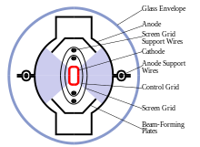
A tetrode is a vacuum tube (called valve in British English) having four active electrodes. The four electrodes in order from the centre are: a thermionic cathode, first and second grids, and a plate (called anode in British English). There are several varieties of tetrodes, the most common being the screen-grid tube and the beam tetrode. In screen-grid tubes and beam tetrodes, the first grid is the control grid and the second grid is the screen grid.[1] In other tetrodes one of the grids is a control grid, while the other may have a variety of functions.
The tetrode was developed in the 1920s by adding an additional grid to the first amplifying vacuum tube, the triode, to correct limitations of the triode. During the period 1913 to 1927, three distinct types of tetrode valves appeared. All had a normal control grid whose function was to act as a primary control for current passing through the tube, but they differed according to the intended function of the other grid. In order of historical appearance these are: the space-charge grid tube, the bi-grid valve, and the screen-grid tube. The last of these appeared in two distinct variants with different areas of application: the screen-grid valve proper, which was used for medium-frequency, small signal amplification, and the beam tetrode which appeared later, and was used for audio or radio-frequency power amplification. The former was quickly superseded by the rf pentode, while the latter was initially developed as an alternative to the pentode as an audio power amplifying device. The beam tetrode was also developed as a high power radio transmitting tube.
Tetrodes were widely used in many consumer electronic devices such as radios, televisions, and audio systems until transistors replaced valves in the 1960s and 70s. Beam tetrodes have remained in use until quite recently in power applications such as audio amplifiers and radio transmitters.
How it works
edit
The tetrode functions in a similar way to the triode, from which it was developed. A current through the heater or filament heats the cathode, which causes it to emit electrons by thermionic emission. A positive voltage is applied between the plate and cathode, causing a flow of electrons from the cathode to plate through the two grids. A varying voltage applied to the control grid can control this current, causing variations in the plate current. With a resistive or other load in the plate circuit, the varying current will result in a varying voltage at the plate. With proper biasing, this voltage will be an amplified (but inverted) version of the AC voltage applied to the control grid, providing voltage gain. In the tetrode, the function of the other grid varies according to the type of tetrode; this is discussed below.
Space charge grid tube
editThe space charge grid tube was the first type of tetrode to appear. In the course of his research into the action of the audion triode tube invented by Edwin Howard Armstrong and Lee de Forest, Irving Langmuir found that the action of the heated thermionic cathode was to create a space charge, or cloud of electrons, around the cathode. This cloud acted as a virtual cathode. With low applied anode voltage, many of the electrons in the space charge returned to the cathode, and did not contribute to the anode current; only those at its outer limit would be affected by the electric field due to the anode, and would be accelerated towards it. However, if a grid bearing a low positive applied potential (about 10V) were inserted between the cathode and the control grid, the space charge could be made to extend further away from the cathode. This had two advantageous effects, both related to the influence of the electric fields of the other electrodes (anode and control grid) on the electrons of the space charge. First, a significant increase in anode current could be achieved with low anode voltage; the valve could be made to work well with lower applied anode voltage.[2] Second, the transconductance (rate of change of anode current with respect to control grid voltage) of the tube was increased. The latter effect was particularly important since it increased the voltage gain available from the valve.[3][4][5]
Space-charge valves remained useful devices throughout the valve era, and were used in applications such as car radios operating directly from a 12V supply, where only a low anode voltage was available. The same principle was applied to other types of multi-grid tubes such as pentodes. As an example, the Sylvania 12K5 is described as "a tetrode designed for space-charge operation. It is intended for service as a power amplifier driver where the potentials are obtained directly from a 12V automobile battery." The space-charge grid was operated at +12V, the same as the anode supply voltage.[6]
Another important application of the space-charge tetrode was as an electrometer tube for detecting and measuring extremely small currents. For example, the General Electric FP54 was described as a "space-charge grid tube ... designed to have a very high input impedance and a very low grid current. It is designed particularly for amplification of direct currents smaller than about 10−9
amperes, and has been found capable of measuring currents as small as 5 x 10⁻¹⁸
amperes. It has a current amplification factor of 250,000, and operates with an anode voltage of 12V, and space-charge grid voltage of +4V."
[7] The mechanism by which the space-charge grid lowers control-grid current in an electrometer tetrode is that it prevents positive ions originating in the cathode from reaching the control grid.[8]
Note that when a space-charge grid is added to a triode, the first grid in the resulting tetrode is the space-charge grid, and the second grid is the control grid.
Bi-grid valve
editIn the bi-grid type of tetrode, both grids are intended to carry electrical signals, so both are control grids. The first example to appear in Britain was the Marconi-Osram FE1, which was designed by H. J. Round, and became available in 1920.[5] The tube was intended to be used in a reflex circuit (for example the single-valve ship receiver Type 91[9]) where the same valve performed the combined functions of RF amplifier, AF amplifier, and diode detector. The RF signal was applied to one control grid, and the AF signal to the other. This type of tetrode was used in many imaginative ways in the period before the appearance of the screen-grid valve revolutionised receiver design.[10][11]

One application is shown in the illustration. This is recognisable as an AM telephony transmitter in which the second grid and the anode form a power oscillator, and the first grid acts as a modulating electrode. The anode current in the valve, and hence the RF output amplitude, is modulated by the voltage on G1, which is derived from a carbon microphone. [12] A tube of this type could also be used as a direct conversion CW (radiotelegraphy) receiver. Here the valve oscillates as a consequence of coupling between the first grid and the anode, while the second grid is coupled to the antenna. The AF beat frequency is audible in the headphones. The valve acts as a self-oscillating product detector.[13] Another, very similar application of the bi-grid valve was as a self oscillating frequency mixer in early superhet receivers[14] One control grid carried the incoming RF signal, while the other was connected into an oscillator circuit which generated the local oscillation within the same valve. Since the anode current of the bi-grid valve was proportional both to the signal on the first grid, and also to the oscillator voltage on the second grid, the required multiplication of the two signals was achieved, and the intermediate frequency signal was selected by a tuned circuit connected to the anode. In each of these applications, the bi-grid tetrode acted as an unbalanced analogue multiplier in which the plate current, in addition to passing both input signals includes the product of the two signals applied to the grids.
The superheterodyne receiver
editThe principle of the modern superheterodyne (or superhet) receiver (originally named the super-sonic heterodyne receiver, because the intermediate frequency was at an ultrasonic frequency) was invented in France by Lucien Levy in 1917[15] (p 66), though credit is usually also given to Edwin Armstrong. The original reason for the invention of the superhet was that before the appearance of the screen-grid valve, amplifying valves, then triodes, had difficulty amplifying radio frequencies (i.e. frequencies much above 100 kHz) due to the Miller effect. In the superheterodyne design, rather than amplifying the incoming radio signal, it was first mixed with a constant RF oscillator (the so-called local oscillator) to produce a heterodyne of typically 30 kHz. This intermediate frequency (IF) signal had an identical envelope as the incoming signal but a much lower carrier frequency, so it could be efficiently amplified using triodes. When detected, the original modulation of the higher frequency radio signal is obtained.[16] A somewhat complicated technique, it went out of favor when screen-grid tetrodes made tuned radio frequency (TRF) receivers practical.[citation needed] However the superheterodyne principle resurfaced in the early 1930s when their other advantages, such as greater selectivity became appreciated, and almost all modern receivers operate on this principle but with a higher IF frequency (sometimes higher than the original RF) with amplifiers (such as the tetrode) having surpassed the triode's limitation in amplifying high (radio) frequency signals.
The superheterodyne concept could be implemented using a valve as the local oscillator and a separate valve as the mixer which takes the antenna signal and the local oscillator as input signals. But for economy, those two functions could also be combined in a single bi-grid tetrode which would both oscillate and frequency-mix the RF signal from the antenna.[14] In later years this was similarly accomplished by the pentagrid converter tube, a similar two-input amplifying/oscillating valve, but which (like pentode tubes) incorporated a suppressor grid and in this case two screen grids in order to electrostatically isolate the plate and both signal grids from each other. In today's receivers, based on inexpensive semiconductor technology (transistors), there is no cost benefit in combining the two functions in one active device.
Screen grid valve
edit


The screen grid tube provides much smaller control grid to anode capacitance and much greater amplification factor than a triode. Radio frequency amplifier circuits using triodes were prone to oscillation due to the grid to anode capacitance of the triode.[17] In the screen grid tube, a grid referred to as the screen grid, shield grid or sometimes accelerating grid is inserted between the control grid and the anode. The screen grid provides an electrostatic shield between the control grid and the anode, reducing the capacitance between them to a very small amount.[17][18] To reduce the influence of the anode's electric field on the cathode space charge and on the control grid, during 1915 - 1916 physicist Walter H. Schottky developed the first tubes having a grid positioned between the anode and the control grid to provide an electrostatic shield.[19][20] Schottky patented these screen grid tubes in Germany in 1916 and in the U.S. in 1919.[21][22] These tubes were produced in Germany and known as Siemens-Schottky tubes.[20] In Japan, Hiroshi Ando patented improvements to the construction of the screen grid in 1919.[23] During the latter half of the 1920s, Neal H. Williams and Albert Hull at General Electric, H. J. Round at MOV and Bernard Tellegen at Phillips developed improved screen grid tubes. These improved screen grid tubes were first marketed in 1927.[24]
Feedback through the anode to grid capacitance (Miller effect) of the triode could cause oscillation, especially when both anode and grid were connected to tuned resonant circuits as is usual in a radio frequency (RF) amplifier.[25] For frequencies above about 100 kHz, neutralizing circuitry was necessary. A typical triode used for small-signal amplification had a grid to anode capacitance of 8 pF, while the corresponding figure for a typical screen grid valve was 0.025 pF.[26] Neutralizing circuits were not required for a well designed screen grid tube RF amplifier stage.[27][28]
The screen grid is connected to a positive DC voltage and at AC ground as insured by a bypass capacitor to ground.[17] The useful region of operation of the screen grid tube as an amplifier is limited to anode voltages greater than the screen grid voltage. At anode voltages greater than the screen grid voltage some electrons from the cathode will hit the screen grid, producing screen current, but most will pass through the open spaces of the screen and continue to the anode.[17] As the anode voltage approaches and falls below that of the screen grid, screen current will increase as shown in the plate characteristics image.
An additional advantage of the screen grid became apparent when it was added. The anode current becomes almost completely independent of the anode voltage, as long as the anode voltage is greater than the screen voltage. This corresponds to a very high anode dynamic resistance, thus allowing for a much larger voltage gain when the anode load impedance is large.[29] The anode current is controlled by the control grid and screen grid voltages. Consequently, tetrodes are mainly characterized by their transconductance (change in anode current relative to control grid voltage) whereas triodes are characterized by their amplification factor (mu), their maximum possible voltage gain. At the time of the introduction of screen grid valves, a typical triode used in radio receivers had an anode dynamic resistance of 20 kΩ or less while the corresponding figure for a typical screen grid valve was 500 kΩ. A typical triode medium wave RF amplifier stage produced voltage gain of around 14, but screen grid tube RF amplifier stages produced voltage gains of 30 to 60.[30]

To take full advantage of the very low grid-anode capacitance, the shielding between anode and grid circuits was observed in the construction of the radio. The S625 valve was mounted in a grounded, plane, metal shield aligned to correspond with the position of the internal screen grid. The input, or control-grid circuit was on one side of the shield, while the anode, or output circuit was on the other. In the receiver shown using S23 tubes, each entire stage of the 2-stage rf amplifier, as well as the tuned detector stage, was enclosed in an individual large metallic box for electrostatic shielding. These boxes have been removed in the illustration, but the up-turned edges of the bases of the boxes can be seen.
Thus screen grid valves permitted better radio frequency amplification in the medium and high frequency ranges in radio equipment. They were commonly used in the design of radio-frequency amplification stage(s) of radio receivers from late 1927 through 1931, then were superseded by the pentode tube.
Anode characteristic of screen-grid valves
editThe reason for the limited applicability of the screen-grid valve, and its rapid replacement by the RF pentode (introduced around 1930) was the peculiar anode characteristic (i.e. variation of anode current with respect to anode voltage) of the former type of tube.
In normal applications, the anode voltage was about 150 V, while that of the screen-grid was about 60 V (Thrower p 183).[5] As the screen grid is positive with respect to the cathode, it collects a certain fraction (perhaps a quarter) of the electrons which would otherwise pass from the grid region to the anode. This causes current to flow in the screen grid circuit. Usually, the screen current due to this cause is small, and of little interest. However, if the anode voltage should be below that of the screen, the screen grid can also collect secondary electrons ejected from the anode by the impact of the energetic primary electrons. Both effects tend to reduce the anode current. If the anode voltage is increased from a low value, with the screen grid at its normal operating voltage (60V, say) the anode current initially increases rapidly because more of those electrons which pass through the screen-grid are collected by the anode rather than passing back to the screen grid. This part of the tetrode anode characteristic resembles the corresponding part of that of a triode or pentode. However, when the anode voltage is increased further, the electrons arriving at the anode have sufficient energy to cause copious secondary emission, and many of these secondary electrons will be captured by the screen, which is at a higher positive voltage than the anode. This causes the anode current to fall rather than increase when the anode voltage is increased. In some cases the anode current can actually become negative (current flows out of the anode); this is possible since each primary electron may produce more than one secondary. Falling positive anode current accompanied by rising anode voltage gives the anode characteristic a region of negative slope, and this corresponds to a negative resistance which can cause instability in certain circuits. In a higher range of anode voltage, the anode voltage sufficiently exceeds that of the screen for an increasing proportion of the secondary electrons to be attracted back to the anode, so the anode current increases once more, and the slope of the anode characteristic becomes positive again. In a yet higher range of anode voltages, the anode current becomes substantially constant, since all of the secondary electrons now return to the anode, and the main control of current through the tube is the voltage of the control grid. This is the normal operating mode of the tube.[31]

The anode characteristic of a screen-grid valve is thus quite unlike that of a triode. Where the anode voltage is less than that of the screen grid, there is a distinctive negative resistance characteristic, called the dynatron region[32] or tetrode kink. The approximately constant-current region of low slope at anode voltages greater than the screen grid voltage is also markedly different from that of the triode, and provides the useful region of operation of the screen grid tube as an amplifier.[33] The low slope is highly desirable, since it greatly enhances the voltage gain which the device can produce. Early screen-grid valves had amplification factors (i.e. the product of transconductance and anode slope resistance, Ra) fifty times or more greater than that of comparable triode.[29] The high anode resistance in the normal operating range is a consequence of the electrostatic shielding action of the screen grid, since it prevents the electric field due to the anode from penetrating to the control grid region, where it might otherwise influence the passage of electrons, increasing the electron current when the anode voltage is high, reducing it when low.

The negative resistance operating region of the tetrode is exploited in the dynatron oscillator, which is an example of a negative resistance oscillator.(Eastman, p431)[4]
Beam tetrode
edit

The beam tetrode eliminates the dynatron region or tetrode kink of the screen grid tube by utilizing partially collimated electron beams to develop a dense low potential space charge region between the screen grid and anode that returns anode secondary emission electrons to the anode.[34] The anode characteristic of the beam tetrode is less rounded at lower anode voltages than the anode characteristic of the power pentode, resulting in greater power output and less third harmonic distortion with the same anode supply voltage.[35][36] Beam tetrodes are usually used for power amplification, from audio frequency to radio frequency. The beam tetrode was patented in Britain in 1933 by three EMI engineers, Isaac Shoenberg, Cabot Bull and Sidney Rodda.[37]
Critical-distance tetrode
editThe High Vacuum Valve company of London, England (Hivac) introduced a line of power output tetrodes in August 1935 that utilized J. H. Owen Harries' critical distance effect to eliminate the dynatron region of the anode voltage - anode current characteristic.[38] The critical distance tubes utilized space charge return of anode secondary electrons to the anode.[39] Distinctive physical characteristics of the critical distance tetrode were large screen grid to anode distance and elliptical grid structure.[38] The large screen grid to anode distance facilitated formation of the low potential space charge to return anode secondary electrons to the anode when the anode potential was less than that of the screen grid.[40] The elliptical grids permitted the control grid support rods to be farther away from the cathode so as to reduce their effect on amplification factor with control grid voltage.[41] At zero and negative control grid voltage, the control grid support rods and control grid formed the electron stream from the cathode into two major regions of space current, 180 degrees apart, directed toward two wide sectors of the anode circumference.[42] These features resulted in somewhat greater output power and lower distortion than a comparable power pentode, due to saturation occurring at lower anode voltage and increased curvature (smaller radius) of the anode voltage - anode current characteristic at low anode voltages.[38] A range of tetrodes of this type were introduced, aimed at the domestic receiver market, some having filaments rated for two volts direct current, intended for low-power battery-operated sets; others having indirectly heated cathodes with heaters rated for four volts or higher for mains operation. Output power ratings ranged from 0.5 watts to 11.5 watts. Confusingly, several of these new valves bore the same type number as existing pentodes with almost identical characteristics. Examples include Y220 (0.5W, 2V filament), AC/Y (3W, 4V heater), AC/Q (11.5W, 4V heater).
See also
editReferences
edit- ^ L.W. Turner, (ed), Electronics Engineer's Reference Book, 4th ed. London: Newnes-Butterworth 1976 ISBN 0408001682 pages 7-19
- ^ Turner, L.B. (1931). Wireless: A treatise on the Theory and Practice of High Frequency Electrical Signalling. Cambridge University Press. pp. 215, 216, 218. ISBN 1420050664.
- ^ Langmuir, I. (29 Oct 1913). US Patent 1,558,437.
- ^ a b Eastman, A.V. (1941). Fundamentals of Vacuum Tubes. New York & London: McGraw-Hill. pp. 89.
- ^ a b c Thrower, K.R. (1992). History of the British Radio Valve to 1940. Beaulieu: MMA International. p. 55. ISBN 0-9520684-0-0.
- ^ Sylvania (December 1956). Engineering Data Service 12K5 (PDF). Emporium, PA: Sylvania Electric Products Inc. Radio Tube Division, Emporium, PA. p. 7.
- ^ General Electric. FP-54 Description and Rating. ETI-160 (PDF). Schenectady, NY: General Electric. pp. 1–5.
- ^ Dolezalek, H. (February 1963). Electrometer Tubes: Part II. Washington: NATIONAL AERONAUTICS AND SPACE ADMINISTRATION. p. 7.
- ^ Scott-Taggart, J. (1922). Elementary Text-Book on Wireless Vacuum Tubes, 4th Edition. Radio Press Ltd. pp. 207–8.
- ^ Goddard, F. (1927). The Four-Electrode Valve. London: Mills & Boon, Ltd.
- ^ Morrow, G.L. (June 1924). A Four Electrode Valve Receiver. E.W. pp. 520–24.
- ^ Scott-Taggart, John (1921). Thermionic Tubes in Radio Telegraphy and Telephony. London: Wireless Press. p. 377.
- ^ Scott-Taggart, John (14 August 1919). British Patent 153,681. London.
{{cite book}}: CS1 maint: location missing publisher (link) - ^ a b Williams, A.L. (1 June 1924). Supersonic Heterodyne Receiver Employing a Four-Electrode Valve. E.W. pp. 525–26.
- ^ <Thrower>
- ^ Murray, O. (1931). Admiralty Handbook of Wireless Telegraphy 1931. London: HMSO. p. 723.
- ^ a b c d Henney, K., Richardson, G. A. (1952) Principles of Radio, 6th ed. New York: John Wiley & Sons. pp. 279 - 282
- ^ Zepler, E. E. (1943) The Technique of Radio Design, New York: John Wiley and Sons. pp. 183–187, 219-221. Retrieved 13 Oct. 2021
- ^ Tapan, Sarkar, Mailloux, Oliner, Salazar-Palma, Sengupta (2006) History of Wireless. New Jersey: John Wiley & Sons Inc. pp. 108 - 109, 344.
- ^ a b Editors (Oct. 1927) "Screened Valves" Experimental Wireless & The Wireless Engineer pp. 585-586.
- ^ Ballantine, Cobb (Mar. 1930) "Power Output Characteristics of the Pentode". Proc. IRE. p. 451.
- ^ H. J. Reich (1944) Theory and Applications of Electron Tubes, 2nd ed.,. New York: McGraw-Hill Book Co. p. 56.
- ^ Brown, L. (1999). Technical and Military Imperatives: A Radar History of World War 2. CRC Press. pp. 35–36. ISBN 9781107636187. (Brown incorrectly gives Ando as first screen grid patent and gives incorrect account of Schottky).
- ^ Editors (Sept. 21, 1927) "Guide to the Show Olympia 1927". Wireless World. p. 375. Retrieved Oct. 12 2021
- ^ Turner, L.B. (1931) p. 257
- ^ E. T. Cunningham, Inc. (1932) The Cunningham Radio Tubes Manual, Technical Series No. C-10, Harrison, NJ: E. T. Cunningham, Inc. pp. 22, 28
- ^ Henney, K. (1938) Principles of Radio, 3rd ed.. New York: John Wiley & Sons, Inc. pp. 327 - 328. Retrieved 14 Oct. 2021
- ^ Hull, Albert W. (April 1926) "Measurements of High Frequency Amplification with Shielded-Grid Pliotrons". Physical Review Vol. 27. pp. 439 - 454.
- ^ a b Rider, John F. (1945). Inside the Vacuum Tube. New York: John F. Rider Publisher Inc. p. 286. Retrieved 10 June 2021
- ^ Henney (1938) pp. 317, 328
- ^ Terman, F.E. (1955). Electronic and Radio Engineering. New York, Toronto, London: McGraw-Hill Book Company Ltd. pp. 196–8.
- ^ Happell, Hesselberth, (1953). Engineering Electronics. New York: McGraw-Hill. p. 88
- ^ John F. Rider, (1945). pp. 293 - 294
- ^ Donovan P. Geppert, (1951) Basic Electron Tubes, New York: McGraw-Hill, pp. 164 - 179. Retrieved 10 June 2021
- ^ Norman H. Crowhurst, (1959) basic audio vol. 2, New York: John F. Rider Publisher Inc., pp. 2-75, 2-76. Retrieved 7 Oct. 2021
- ^ J. F. Dreyer Jr., (April 1936) "The Beam Power Output Tube". New York: McGraw-Hill, Electronics p. 21
- ^ Schoenberg, Rodda, Bull, (1935) Improvements in and relating to thermionic valves, GB patent 423,932
- ^ a b c Harries, J. H. Owen. (Aug. 2nd, 1935). "A New Power Output Valve". Wireless World, pp. 105 - 106
- ^ Rodda, S. (Jun. 1945). "Space Charge and Electron Deflections in Beam Tetrode Theory". Electronic Engineering, p. 542
- ^ Schade, O. H. (Feb. 1938)."Beam Power Tubes" Proc. I.R.E., Vol. 26, No. 2, p. 169
- ^ Salzberg, Bernard. (1937). Electron discharge device. U.S. patent 2,073,946
- ^ RCA. (1940). Vacuum Tube Design. Harrison, NJ: RCA Manufacturing Co., Inc. pp. 241, 243