


Summary
Light-emitting diodes (LEDs) produce light (or infrared radiation) by the recombination of electrons and electron holes in a semiconductor, a process called "electroluminescence". The wavelength of the light produced depends on the energy band gap of the semiconductors used. Since these materials have a high index of refraction,[note 1] design features of the devices such as special optical coatings and die shape are required to efficiently emit light. A LED is a long-lived light source, but certain mechanisms can cause slow loss of efficiency of the device or sudden failure. The wavelength of the light emitted is a function of the band gap of the semiconductor material used; materials such as gallium arsenide, and others, with various trace doping elements, are used to produce different colors of light. Another type of LED uses a quantum dot which can have its properties and wavelength adjusted by its size. Light-emitting diodes are widely used in indicator and display functions, and white LEDs are displacing other technologies for general illumination purposes.
Electroluminescence edit
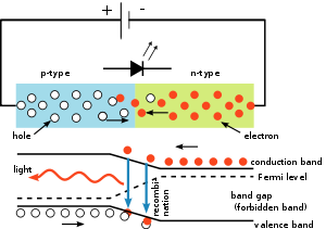
The p–n junction in any direct band gap material emits light when electric current flows through it. This is electroluminescence. Electrons cross from the n-region and recombine with the holes existing in the p-region. Free electrons are in the conduction band of energy levels, while holes are in the valence energy band. Thus the energy level of the holes is lower than the energy levels of the electrons. Some portion of the energy must be dissipated to recombine the electrons and the holes. This energy is emitted in the form of heat and light.
As indirect band gap materials the electrons dissipate energy in the form of heat within the crystalline silicon and germanium diodes, but in gallium arsenide phosphide (GaAsP) and gallium phosphide (GaP) semiconductors, the electrons dissipate energy by emitting photons. If the semiconductor is translucent, the junction becomes the source of light, thus becoming a light-emitting diode.
The wavelength of the light emitted, and thus its color, depends on the band gap energy of the materials forming the p-n junction. In silicon or germanium diodes, the electrons and holes usually recombine by a non-radiative transition, which produces no optical emission, because these are indirect band gap materials. The materials used for the LED have a direct band gap with energies corresponding to near-infrared, visible, or near-ultraviolet light.
LED development began with infrared and red devices made with gallium arsenide. Advances in materials science have enabled making devices with ever-shorter wavelengths, emitting light in a variety of colors.
LEDs are usually built on an n-type substrate, with an electrode attached to the p-type layer deposited on its surface. P-type substrates, while less common, occur as well. Many commercial LEDs, especially GaN/InGaN, also use sapphire substrates.
Refractive index edit

Bare uncoated semiconductors such as silicon exhibit a very high refractive index relative to air. Photons that approach the surface at too great an angle to the perpendicular experience total internal reflection. This property affects both the light-emission efficiency of LEDs as well as the light-absorption efficiency of photovoltaic cells. The refractive index of silicon is 3.96 (at 590 nm),[2] while air's refractive index is 1.0002926.[3]
In general, a flat-surface uncoated LED semiconductor chip emits only light that arrives nearly perpendicular to the semiconductor's surface, in a cone shape referred to as the light cone, cone of light,[4] or the escape cone.[1] Photons arriving at the surface more obliquely, with incidence angle exceeding the critical angle, undergo total internal reflection, and return inside the semiconductor crystal as if its surface were a mirror.[1]
Internal reflections can escape through other crystalline faces if the incidence angle is low enough and the crystal is sufficiently transparent to not re-absorb the photon emission. But for a simple square LED with 90-degree angled surfaces on all sides, the faces all act as equal angle mirrors. In this case, most of the light can not escape and is lost as waste heat in the crystal.[1]
A convoluted chip surface with angled facets similar to a jewel or fresnel lens can increase light output by distributing light perpendicular to the chip surface and far to the sides of the photon emission point.[5]
The ideal shape of a semiconductor with maximum light output would be a microsphere with the photon emission occurring at the exact center, with electrodes penetrating to the center to contact at the emission point. All light rays emanating from the center would be perpendicular to the entire surface of the sphere, resulting in no internal reflections. A hemispherical semiconductor would also work, with the flat back-surface serving as a mirror to back-scattered photons.[6]
Transition coatings edit
After the doping of the wafer, it is usually cut apart into individual dies. Each die is commonly called a chip.
Many LED semiconductor chips are encapsulated or potted in clear or colored molded solid plastic. The plastic encapsulation has three purposes:
- Mounting the semiconductor chip in devices is easier to accomplish.
- The tiny fragile electrical wiring is physically supported and protected from damage.
- The plastic acts as a refractive intermediary between the relatively high-index semiconductor and low-index open air.[7]
The third feature helps to boost the light emission from the semiconductor by reducing Fresnel reflections of photons within the light cone. A flat coating does not directly increase the size of the light cone in the semiconductor; it provides an intermediate wider cone angle in the coating, but the critical angle between rays in the semiconductor and in the air beyond the coating does not change. With a curved coating or encapsulation, however, efficiency can be further increased.
Efficiency and operational parameters edit
Typical indicator LEDs are designed to operate with no more than 30–60 milliwatts (mW) of electrical power. Around 1999, Philips Lumileds introduced power LEDs capable of continuous use at one watt. These LEDs used much larger semiconductor die sizes to handle the large power inputs. Also, the semiconductor dies were mounted onto metal slugs to allow for greater heat dissipation from the LED die.
One of the key advantages of LED-based lighting sources is high luminous efficacy. White LEDs quickly matched and overtook the efficacy of standard incandescent lighting systems. In 2002, Lumileds made five-watt LEDs available with luminous efficacy of 18–22 lumens per watt (lm/W). For comparison, a conventional incandescent light bulb of 60–100 watts emits around 15 lm/W, and standard fluorescent lights emit up to 100 lm/W.
As of 2012[update], Philips had achieved the following efficacies for each color.[8] The efficiency values show the physics – light power out per electrical power in. The lumen-per-watt efficacy value includes characteristics of the human eye and is derived using the luminosity function.
| Color | Wavelength range (nm) | Typical efficiency coefficient | Typical efficacy (lm/W) | |
|---|---|---|---|---|
| Red | 620 < λ < 645 | 0.39 | 72 | |
| Red-orange | 610 < λ < 620 | 0.29 | 98 | |
| Green | 520 < λ < 550 | 0.15 | 93 | |
| Cyan | 490 < λ < 520 | 0.26 | 75 | |
| Blue | 460 < λ < 490 | 0.35 | 37 | |
In September 2003, a new type of blue LED was demonstrated by Cree. This produced a commercially packaged white light giving 65 lm/W at 20 mA, becoming the brightest white LED commercially available at the time, and more than four times as efficient as standard incandescents. In 2006, they demonstrated a prototype with a record white LED luminous efficacy of 131 lm/W at 20 mA. Nichia Corporation has developed a white LED with luminous efficacy of 150 lm/W at a forward current of 20 mA.[9] Cree's XLamp XM-L LEDs, commercially available in 2011, produce 100 lm/W at their full power of 10 W, and up to 160 lm/W at around 2 W input power. In 2012, Cree announced a white LED giving 254 lm/W,[10] and 303 lm/W in March 2014.[11] Practical general lighting needs high-power LEDs, of one watt or more. Typical operating currents for such devices begin at 350 mA.
These efficiencies are for the light-emitting diode only, held at low temperature in a lab. Since LEDs installed in real fixtures operate at higher temperature and with driver losses, real-world efficiencies are much lower. United States Department of Energy (DOE) testing of commercial LED lamps designed to replace incandescent lamps or CFLs showed that average efficacy was still about 46 lm/W in 2009 (tested performance ranged from 17 lm/W to 79 lm/W).[12]
Efficiency droop edit
Efficiency droop is the decrease in luminous efficacy of LEDs as the electric current increases.
This effect was initially thought related to elevated temperatures. Scientists proved the opposite is true: though the life of an LED is shortened, the efficiency droop is less severe at elevated temperatures.[13] The mechanism causing efficiency droop was identified in 2007 as Auger recombination.[14][15]
In addition to being less efficient, operating LEDs at higher electric currents creates more heat, which can compromise LED lifetime. High-brightness LEDs often operate at 350 mA, which is a compromise between light output, efficiency, and longevity.[14]
Instead of increasing current levels, luminance is usually increased by combining multiple LEDs in one bulb. Solving the problem of efficiency droop would mean that household LED light bulbs would need fewer LEDs, which would significantly reduce costs.
Researchers at the U.S. Naval Research Laboratory have found a way to lessen the efficiency droop. They found that the droop arises from non-radiative Auger recombination of the injected carriers. They created quantum wells with a soft confinement potential to lessen the non-radiative Auger processes.[16]
Researchers at Taiwan National Central University and Epistar Corp are developing a way to lessen the efficiency droop by using ceramic aluminium nitride (AlN) substrates, which are more thermally conductive than the commercially used sapphire. The higher thermal conductivity reduces self-heating effects.[17]
Lifetime and failure edit
Solid-state devices such as LEDs are subject to very limited wear and tear if operated at low currents and at low temperatures. Typical lifetimes quoted are 25,000 to 100,000 hours, but heat and current settings can extend or shorten this time significantly.[18] It is important to note that these projections are based on a standard test that may not accelerate all the potential mechanisms that can induce failures in LEDs.[19]
The most common symptom of LED failure is the gradual lowering of light output. Sudden failures, although rare, can also occur. Early red LEDs were notable for their short service life. With the development of high-power LEDs, the devices are subjected to higher junction temperatures and higher current densities than traditional devices. This causes stress on the material and may cause early light-output degradation. Lifetime of a LED may be given as the running time to 70% or 50% of initial output.[20]
Unlike combustion or incandescent lamps, LEDs only operate if they are kept cool enough. The manufacturer commonly specifies a maximum junction temperature of 125 or 150 °C, and lower temperatures are advisable in the interests of long life. At these temperatures, relatively little heat is lost by radiation, which means that the light beam generated by an LED is cool.
The waste heat in a high-power LED is conducted through the device to a heat sink, which dissipates heat to the surrounding air. Since the maximum operating temperature of the LED is limited, the thermal resistances of the package, the heat sink and the interface must be calculated. Medium-power LEDs are often designed to solder directly to a printed circuit board that contains a thermally conductive metal layer. High-power LEDs are packaged in large-area ceramic packages that attach to a metal heat sink using thermal grease or other material to conduct heat.
If an LED lamp does not have free air circulation, the LED is likely to overheat, resulting in reduced life or early failure. The thermal design of the system must allow for the ambient temperature surrounding the lamp; a lamp in a freezer experiences a lower ambient than a lamp in a billboard in a sunny climate.[21]
Materials edit
LEDs are made from a variety of inorganic semiconductor materials. The following table shows the available colors with wavelength range, voltage drop, and material:
| Color | Wavelength [nm] | Voltage drop [ΔV] | Semiconductor material | |
|---|---|---|---|---|
| Infrared | λ > 760 | ΔV < 1.63 | Gallium arsenide (GaAs) Aluminium gallium arsenide (AlGaAs) | |
| Red | 610 < λ < 760 | 1.63 < ΔV < 2.03 | Aluminium gallium arsenide (AlGaAs) Gallium arsenide phosphide (GaAsP) Aluminium gallium indium phosphide (AlGaInP) Gallium(III) phosphide (GaP) | |
| Orange | 590 < λ < 610 | 2.03 < ΔV < 2.10 | Gallium arsenide phosphide (GaAsP) Aluminium gallium indium phosphide (AlGaInP) Gallium(III) phosphide (GaP) | |
| Yellow | 570 < λ < 590 | 2.10 < ΔV < 2.18 | Gallium arsenide phosphide (GaAsP) Aluminium gallium indium phosphide (AlGaInP) Gallium(III) phosphide (GaP) | |
| Green | 500 < λ < 570 | 1.9[22] < ΔV < 4.0 | Traditional green: Gallium(III) phosphide (GaP) Aluminium gallium indium phosphide (AlGaInP) Aluminium gallium phosphide (AlGaP) Pure green: Indium gallium nitride (InGaN) / Gallium(III) nitride (GaN) | |
| Blue | 450 < λ < 500 | 2.48 < ΔV < 3.7 | Zinc selenide (ZnSe) Indium gallium nitride (InGaN) Synthetic sapphire, Silicon carbide (SiC) as substrate with or without epitaxy, Silicon (Si) as substrate—under development (epitaxy on silicon is hard to control) | |
| Violet | 400 < λ < 450 | 2.76 < ΔV < 4.0 | Indium gallium nitride (InGaN) | |
| Ultraviolet | λ < 400 | 3 < ΔV < 4.1 | Indium gallium nitride (InGaN) (385-400 nm)
Diamond (235 nm)[23] | |
| Pink | Multiple types | ΔV ≈3.3[28] | Blue with one or two phosphor layers, yellow with red, orange or pink phosphor added afterwards, white with pink plastic, | |
| Purple | Multiple types | 2.48 < ΔV < 3.7 | Dual blue/red LEDs, blue with red phosphor, or white with purple plastic | |
| White | Broad spectrum | 2.8 < ΔV < 4.2 | Cool / Pure White: Blue/UV diode with yellow phosphor Warm White: Blue diode with orange phosphor | |
Quantum-dot LEDs edit
Quantum dots (QD) are semiconductor nanocrystals with optical properties that let their emission color be tuned from the visible into the infrared spectrum.[30][31] This allows quantum dot LEDs to create almost any color on the CIE diagram. This provides more color options and better color rendering than white LEDs since the emission spectrum is much narrower, characteristic of quantum confined states.
There are two types of schemes for QD excitation. One uses photo excitation with a primary light source LED (typically blue or UV LEDs are used). The other is direct electrical excitation first demonstrated by Alivisatos et al.[32]
One example of the photo-excitation scheme is a method developed by Michael Bowers, at Vanderbilt University in Nashville, involving coating a blue LED with quantum dots that glow white in response to the blue light from the LED. This method emits a warm, yellowish-white light similar to that made by incandescent light bulbs.[33] Quantum dots are also being considered for use in white light-emitting diodes in liquid crystal display (LCD) televisions.[34]
In February 2011 scientists at PlasmaChem GmbH were able to synthesize quantum dots for LED applications and build a light converter on their basis, which was able to efficiently convert light from blue to any other color for many hundred hours.[35] Such QDs can be used to emit visible or near infrared light of any wavelength being excited by light with a shorter wavelength.
The structure of QD-LEDs used for the electrical-excitation scheme is similar to basic design of OLEDs. A layer of quantum dots is sandwiched between layers of electron-transporting and hole-transporting materials. An applied electric field causes electrons and holes to move into the quantum dot layer and recombine forming an exciton that excites a QD. This scheme is commonly studied for quantum dot display. The tunability of emission wavelengths and narrow bandwidth is also beneficial as excitation sources for fluorescence imaging. Fluorescence near-field scanning optical microscopy (NSOM) utilizing an integrated QD-LED has been demonstrated.[36]
In February 2008, a luminous efficacy of 300 lumens of visible light per watt of radiation (not per electrical watt) and warm-light emission was achieved by using nanocrystals.[37]
Notes edit
- ^ thereby prone to internal reflection, i.e. not actually emitting the light to the outside
References edit
- ^ a b c d Mueller, Gerd (2000) Electroluminescence I, Academic Press, ISBN 0-12-752173-9, p. 67, "escape cone of light" from semiconductor, illustrations of light cones on p. 69
- ^ "Optical Properties of Silicon". PVCDROM.PVEducation.org. Archived from the original on 2009-06-05.
- ^ Refraction — Snell's Law. Interactagram.com. Retrieved on March 16, 2012.
- ^ Lipták, Bela G. (2005) Instrument Engineers' Handbook: Process control and optimization, CRC Press, ISBN 0-8493-1081-4 p. 537, "cone of light" in context of optical fibers
- ^ Capper, Peter; Mauk, Michael (2007). Liquid phase epitaxy of electronic, optical, and optoelectronic materials. Wiley. p. 389. ISBN 978-0-470-85290-3.
faceted structures are of interest for solar cells, LEDs, thermophotovoltaic devices, and detectors in that nonplanar surfaces and facets can enhance optical coupling and light-trapping effects, [with example microphotograph of a faceted crystal substrate].
- ^ Dakin, John and Brown, Robert G. W. (eds.) Handbook of optoelectronics, Volume 2, Taylor & Francis, 2006 ISBN 0-7503-0646-7 p. 356, "Die shaping is a step towards the ideal solution, that of a point light source at the center of a spherical semiconductor die."
- ^ Schubert, E. Fred (2006) Light-emitting diodes, Cambridge University Press, ISBN 0-521-86538-7 p. 97, "Epoxy Encapsulants", "The light extraction efficiency can be enhanced by using dome-shaped encapsulants with a large refractive index."
- ^ "All in 1 LED Lighting Solutions Guide". PhilipsLumileds.com. Philips. 2012-10-04. p. 15. Archived from the original (PDF) on March 14, 2013. Retrieved 2015-11-18.
- ^ "Nichia Unveils White LED with 150 lm/W Luminous Efficiency". Tech-On!. December 21, 2006. Retrieved August 13, 2007.
- ^ "Cree Sets New Record for White LED Efficiency", Tech-On, April 23, 2012.
- ^ "Cree First to Break 300 Lumens-Per-Watt Barrier", Cree news
- ^ DOE Solid-State Lighting CALiPER Program Summary of Results: Round 9 of Product Testing (PDF). U.S. Department of Energy. October 2009.
- ^ Identifying the Causes of LED Efficiency Droop Archived December 13, 2013, at the Wayback Machine, By Steven Keeping, Digi-Key Corporation Tech Zone
- ^ a b Stevenson, Richard (August 2009) The LED’s Dark Secret: Solid-state lighting won't supplant the lightbulb until it can overcome the mysterious malady known as droop Archived 2009-08-05 at the Wayback Machine. IEEE Spectrum
- ^ Iveland, Justin; Martinelli, Lucio; Peretti, Jacques; Speck, James S.; Weisbuch, Claude. "Cause of LED Efficiency Droop Finally Revealed". Physical Review Letters, 2013. Science Daily. Retrieved 23 April 2013.
- ^ McKinney, Donna (19 February 2014) A Roadmap to Efficient Green-Blue-Ultraviolet Light-Emitting Diodes, U.S. Naval Research Laboratory
- ^ Cooke, Mike (11 February 2014) Enabling high-voltage InGaN LED operation with ceramic substrate, Semiconductor Today
- ^ "Lifetime of White LEDs". Archived from the original on April 10, 2009. Retrieved 2009-04-10., US Department of Energy
- ^ Arnold, J. When the Lights Go Out: LED Failure Modes and Mechanisms. DfR Solutions
- ^ Narendran, N.; Y. Gu (2005). "Life of LED-based white light sources". Journal of Display Technology. 1 (1): 167–171. Bibcode:2005JDisT...1..167N. doi:10.1109/JDT.2005.852510. S2CID 32847174.
- ^ Conway, K. M. and J. D. Bullough. 1999. Will LEDs transform traffic signals as they did exit signs? Proceedings of the Illuminating Engineering Society of North America Annual Conference (pp. 1–9), New Orleans, Louisiana, August 9–11. New York, NY: Illuminating Engineering Society of North America.
- ^ OSRAM: green LED Archived July 21, 2011, at the Wayback Machine. osram-os.com. Retrieved on March 16, 2012.
- ^ Koizumi, S.; Watanabe, K.; Hasegawa, M.; Kanda, H. (2001). "Ultraviolet Emission from a Diamond pn Junction". Science. 292 (5523): 1899–1901. Bibcode:2001Sci...292.1899K. doi:10.1126/science.1060258. PMID 11397942. S2CID 10675358.
- ^ Kubota, Y.; Watanabe, K.; Tsuda, O.; Taniguchi, T. (2007). "Deep Ultraviolet Light-Emitting Hexagonal Boron Nitride Synthesized at Atmospheric Pressure". Science. 317 (5840): 932–934. Bibcode:2007Sci...317..932K. doi:10.1126/science.1144216. PMID 17702939. S2CID 196949298.
- ^ Watanabe, K.; Taniguchi, T.; Kanda, H. (2004). "Direct-bandgap properties and evidence for ultraviolet lasing of hexagonal boron nitride single crystal". Nature Materials. 3 (6): 404–409. Bibcode:2004NatMa...3..404W. doi:10.1038/nmat1134. PMID 15156198. S2CID 23563849.
- ^ Taniyasu, Y.; Kasu, M.; Makimoto, T. (2006). "An aluminium nitride light-emitting diode with a wavelength of 210 nanometres". Nature. 441 (7091): 325–328. Bibcode:2006Natur.441..325T. doi:10.1038/nature04760. PMID 16710416. S2CID 4373542.
- ^ "LEDs move into the ultraviolet". physicsworld.com. May 17, 2006. Retrieved August 13, 2007.
- ^ How to Wire/Connect LEDs Archived March 2, 2012, at the Wayback Machine. Llamma.com. Retrieved on March 16, 2012.
- ^ LED types by Color, Brightness, and Chemistry. Donklipstein.com. Retrieved on March 16, 2012.
- ^ Quantum-dot LED may be screen of choice for future electronics Massachusetts Institute of Technology News Office, December 18, 2002
- ^ Neidhardt, H.; Wilhelm, L.; Zagrebnov, V. A. (February 2015). "A New Model for Quantum Dot Light Emitting-Absorbing Bevices: Proofs and Supplements". Nanosystems: Physics, Chemistry, Mathematics. 6 (1): 6–45. doi:10.17586/2220-8054-2015-6-1-6-45.
- ^ Colvin, V. L.; Schlamp, M. C.; Alivisatos, A. P. (1994). "Light-emitting diodes made from cadmium selenide nanocrystals and a semiconducting polymer". Nature. 370 (6488): 354–357. Bibcode:1994Natur.370..354C. doi:10.1038/370354a0. S2CID 4324973.
- ^ "Accidental Invention Points to End of Light Bulbs". LiveScience.com. October 21, 2005. Retrieved January 24, 2007.
- ^ Nanoco Signs Agreement with Major Japanese Electronics Company, nanocogroup.com (September 23, 2009)
- ^ Nanotechnologie Aktuell, pp. 98–99, v. 4, 2011, ISSN 1866-4997
- ^ Hoshino, K.; Gopal, A.; Glaz, M. S.; Vanden Bout, D. A.; Zhang, X. (2012). "Nanoscale fluorescence imaging with quantum dot near-field electroluminescence". Applied Physics Letters. 101 (4): 043118. Bibcode:2012ApPhL.101d3118H. doi:10.1063/1.4739235.
- ^ Inman, Mason (February 1, 2008). "Crystal Coat Warms up LED Light". newscientist.com. Retrieved January 30, 2012.