


Summary
In optics, the refractive index (or refraction index) of an optical medium is a dimensionless number that gives the indication of the light bending ability of that medium.

The refractive index determines how much the path of light is bent, or refracted, when entering a material. This is described by Snell's law of refraction, n1 sin θ1 = n2 sin θ2, where θ1 and θ2 are the angle of incidence and angle of refraction, respectively, of a ray crossing the interface between two media with refractive indices n1 and n2. The refractive indices also determine the amount of light that is reflected when reaching the interface, as well as the critical angle for total internal reflection, their intensity (Fresnel equations) and Brewster's angle.[1]
The refractive index, , can be seen as the factor by which the speed and the wavelength of the radiation are reduced with respect to their vacuum values: the speed of light in a medium is v = c/n, and similarly the wavelength in that medium is λ = λ0/n, where λ0 is the wavelength of that light in vacuum. This implies that vacuum has a refractive index of 1, and assumes that the frequency (f = v/λ) of the wave is not affected by the refractive index.

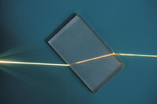
The refractive index may vary with wavelength. This causes white light to split into constituent colors when refracted. This is called dispersion. This effect can be observed in prisms and rainbows, and as chromatic aberration in lenses. Light propagation in absorbing materials can be described using a complex-valued refractive index.[2] The imaginary part then handles the attenuation, while the real part accounts for refraction. For most materials the refractive index changes with wavelength by several percent across the visible spectrum. Consequently, refractive indices for materials reported using a single value for n must specify the wavelength used in the measurement.
The concept of refractive index applies across the full electromagnetic spectrum, from X-rays to radio waves. It can also be applied to wave phenomena such as sound. In this case, the speed of sound is used instead of that of light, and a reference medium other than vacuum must be chosen.[3]
For lenses (such as eye glasses), a lens made from a high refractive index material will be thinner, and hence lighter, than a conventional lens with a lower refractive index. Such lenses are generally more expensive to manufacture than conventional ones.
Definition edit
The relative refractive index of an optical medium 2 with respect to another reference medium 1 (n21) is given by the ratio of speed of light in medium 1 to that in medium 2. This can be expressed as follows:

The absolute refractive index n of an optical medium is defined as the ratio of the speed of light in vacuum, c = 299792458 m/s, and the phase velocity v of light in the medium,


History edit

Thomas Young was presumably the person who first used, and invented, the name "index of refraction", in 1807.[4] At the same time he changed this value of refractive power into a single number, instead of the traditional ratio of two numbers. The ratio had the disadvantage of different appearances. Newton, who called it the "proportion of the sines of incidence and refraction", wrote it as a ratio of two numbers, like "529 to 396" (or "nearly 4 to 3"; for water).[5] Hauksbee, who called it the "ratio of refraction", wrote it as a ratio with a fixed numerator, like "10000 to 7451.9" (for urine).[6] Hutton wrote it as a ratio with a fixed denominator, like 1.3358 to 1 (water).[7]
Young did not use a symbol for the index of refraction, in 1807. In the later years, others started using different symbols: n, m, and µ.[8][9][10] The symbol n gradually prevailed.
Typical values edit
Refractive index also varies with wavelength of the light as given by Cauchy's equation:
The most general form of Cauchy's equation is

Usually, it is sufficient to use a two-term form of the equation:

| Material | n |
|---|---|
| Vacuum | 1 |
| Gases at 0 °C and 1 atm | |
| Air | 1.000293 |
| Helium | 1.000036 |
| Hydrogen | 1.000132 |
| Carbon dioxide | 1.00045 |
| Liquids at 20 °C | |
| Water | 1.333 |
| Ethanol | 1.36 |
| Olive oil | 1.47 |
| Solids | |
| Ice | 1.31 |
| Fused silica (quartz) | 1.46[11] |
| PMMA (acrylic, plexiglas, lucite, perspex) | 1.49 |
| Window glass | 1.52[12] |
| Polycarbonate (Lexan™) | 1.58[13] |
| Flint glass (typical) | 1.69 |
| Sapphire | 1.77[14] |
| Cubic zirconia | 2.15 |
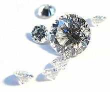
| Diamond | 2.417 |
| Moissanite | 2.65 |
For visible light most transparent media have refractive indices between 1 and 2. A few examples are given in the adjacent table. These values are measured at the yellow doublet D-line of sodium, with a wavelength of 589 nanometers, as is conventionally done.[15] Gases at atmospheric pressure have refractive indices close to 1 because of their low density. Almost all solids and liquids have refractive indices above 1.3, with aerogel as the clear exception. Aerogel is a very low density solid that can be produced with refractive index in the range from 1.002 to 1.265.[16] Moissanite lies at the other end of the range with a refractive index as high as 2.65. Most plastics have refractive indices in the range from 1.3 to 1.7, but some high-refractive-index polymers can have values as high as 1.76.[17]
For infrared light refractive indices can be considerably higher. Germanium is transparent in the wavelength region from 2 to 14 μm and has a refractive index of about 4.[18] A type of new materials termed "topological insulators", was recently found which have high refractive index of up to 6 in the near to mid infrared frequency range. Moreover, topological insulators are transparent when they have nanoscale thickness. These properties are potentially important for applications in infrared optics.[19]
Refractive index below unity edit
According to the theory of relativity, no information can travel faster than the speed of light in vacuum, but this does not mean that the refractive index cannot be less than 1. The refractive index measures the phase velocity of light, which does not carry information.[20][a] The phase velocity is the speed at which the crests of the wave move and can be faster than the speed of light in vacuum, and thereby give a refractive index below 1. This can occur close to resonance frequencies, for absorbing media, in plasmas, and for X-rays. In the X-ray regime the refractive indices are lower than but very close to 1 (exceptions close to some resonance frequencies).[21] As an example, water has a refractive index of 0.99999974 = 1 − 2.6×10⁻⁷ for X-ray radiation at a photon energy of 30 keV (0.04 nm wavelength).[21]
An example of a plasma with an index of refraction less than unity is Earth's ionosphere. Since the refractive index of the ionosphere (a plasma), is less than unity, electromagnetic waves propagating through the plasma are bent "away from the normal" (see Geometric optics) allowing the radio wave to be refracted back toward earth, thus enabling long-distance radio communications. See also Radio Propagation and Skywave.[22]
Negative refractive index edit
Recent research has also demonstrated the "existence" of materials with a negative refractive index, which can occur if permittivity and permeability have simultaneous negative values.[23] This can be achieved with periodically constructed metamaterials. The resulting negative refraction (i.e., a reversal of Snell's law) offers the possibility of the superlens and other new phenomena to be actively developed by means of metamaterials.[24][25]
Microscopic explanation edit
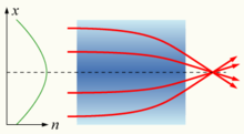
At the atomic scale, an electromagnetic wave's phase velocity is slowed in a material because the electric field creates a disturbance in the charges of each atom (primarily the electrons) proportional to the electric susceptibility of the medium. (Similarly, the magnetic field creates a disturbance proportional to the magnetic susceptibility.) As the electromagnetic fields oscillate in the wave, the charges in the material will be "shaken" back and forth at the same frequency.[1]: 67 The charges thus radiate their own electromagnetic wave that is at the same frequency, but usually with a phase delay, as the charges may move out of phase with the force driving them (see sinusoidally driven harmonic oscillator). The light wave traveling in the medium is the macroscopic superposition (sum) of all such contributions in the material: the original wave plus the waves radiated by all the moving charges. This wave is typically a wave with the same frequency but shorter wavelength than the original, leading to a slowing of the wave's phase velocity. Most of the radiation from oscillating material charges will modify the incoming wave, changing its velocity. However, some net energy will be radiated in other directions or even at other frequencies (see scattering).
Depending on the relative phase of the original driving wave and the waves radiated by the charge motion, there are several possibilities:
- If the electrons emit a light wave which is 90° out of phase with the light wave shaking them, it will cause the total light wave to travel slower. This is the normal refraction of transparent materials like glass or water, and corresponds to a refractive index which is real and greater than 1.[26][page needed]
- If the electrons emit a light wave which is 270° out of phase with the light wave shaking them, it will cause the wave to travel faster. This is called "anomalous refraction", and is observed close to absorption lines (typically in infrared spectra), with X-rays in ordinary materials, and with radio waves in Earth's ionosphere. It corresponds to a permittivity less than 1, which causes the refractive index to be also less than unity and the phase velocity of light greater than the speed of light in vacuum c (note that the signal velocity is still less than c, as discussed above). If the response is sufficiently strong and out-of-phase, the result is a negative value of permittivity and imaginary index of refraction, as observed in metals or plasma.[26][page needed]
- If the electrons emit a light wave which is 180° out of phase with the light wave shaking them, it will destructively interfere with the original light to reduce the total light intensity. This is light absorption in opaque materials and corresponds to an imaginary refractive index.
- If the electrons emit a light wave which is in phase with the light wave shaking them, it will amplify the light wave. This is rare, but occurs in lasers due to stimulated emission. It corresponds to an imaginary index of refraction, with the opposite sign to that of absorption.
For most materials at visible-light frequencies, the phase is somewhere between 90° and 180°, corresponding to a combination of both refraction and absorption.
Dispersion edit

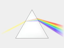
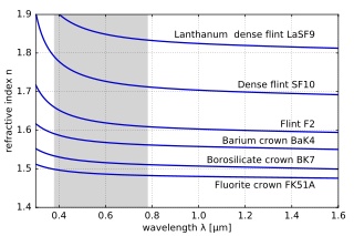
The refractive index of materials varies with the wavelength (and frequency) of light.[27] This is called dispersion and causes prisms and rainbows to divide white light into its constituent spectral colors.[28] As the refractive index varies with wavelength, so will the refraction angle as light goes from one material to another. Dispersion also causes the focal length of lenses to be wavelength dependent. This is a type of chromatic aberration, which often needs to be corrected for in imaging systems. In regions of the spectrum where the material does not absorb light, the refractive index tends to decrease with increasing wavelength, and thus increase with frequency. This is called "normal dispersion", in contrast to "anomalous dispersion", where the refractive index increases with wavelength.[27] For visible light normal dispersion means that the refractive index is higher for blue light than for red.
For optics in the visual range, the amount of dispersion of a lens material is often quantified by the Abbe number:[28]

Principal refractive index wavelength ambiguity edit
Because of dispersion, it is usually important to specify the vacuum wavelength of light for which a refractive index is measured. Typically, measurements are done at various well-defined spectral emission lines.
Manufacturers of optical glass in general define principal index of refraction at yellow spectral line of helium (587.56 nm) and alternatively at a green spectral line of mercury (546.07 nm), called d and e lines respectively. Abbe number is defined for both and denoted Vd and Ve. The spectral data provided by glass manufacturers is also often more precise for these two wavelengths.[30][31][32][33]
Both, d and e spectral lines are singlets and thus are suitable to perform a very precise measurements, such as spectral goniometric method.[34][35]
In practical applications, measurements of refractive index are performed on various refractometers, such as Abbe refractometer. Measurement accuracy of such typical commercial devices is in the order of 0.0002.[36][37] Refractometers usually measure refractive index nD, defined for sodium doublet D (589.29 nm), which is actually a midpoint between two adjacent yellow spectral lines of sodium. Yellow spectral lines of helium (d) and sodium (D) are 1.73 nm apart, which can be considered negligible for typical refractometers, but can cause confusion and lead to errors if accuracy is critical.
All three typical principle refractive indices definitions can be found depending on application and region,[38] so a proper subscript should be used to avoid ambiguity.
Complex refractive index edit
When light passes through a medium, some part of it will always be absorbed. This can be conveniently taken into account by defining a complex refractive index,

Here, the real part n is the refractive index and indicates the phase velocity, while the imaginary part κ is called the optical extinction coefficient or absorption coefficient—although κ can also refer to the mass attenuation coefficient[39]: 3 —and indicates the amount of attenuation when the electromagnetic wave propagates through the material.[1]: 128
That κ corresponds to absorption can be seen by inserting this refractive index into the expression for electric field of a plane electromagnetic wave traveling in the x-direction. This can be done by relating the complex wave number k to the complex refractive index n through k = 2πn/λ0, with λ0 being the vacuum wavelength; this can be inserted into the plane wave expression for a wave travelling in the x-direction as:
![{\displaystyle {\begin{aligned}\mathbf {E} (x,t)&=\operatorname {Re} \!\left[\mathbf {E} _{0}e^{i({\underline {k}}x-\omega t)}\right]\\&=\operatorname {Re} \!\left[\mathbf {E} _{0}e^{i(2\pi (n+i\kappa )x/\lambda _{0}-\omega t)}\right]\\&=e^{-2\pi \kappa x/\lambda _{0}}\operatorname {Re} \!\left[\mathbf {E} _{0}e^{i(kx-\omega t)}\right].\end{aligned}}}](https://wikimedia.org/api/rest_v1/media/math/render/svg/5e3936daed1b1eca2f8adf0bc77d7e57269bb7cd)
Here we see that κ gives an exponential decay, as expected from the Beer–Lambert law. Since intensity is proportional to the square of the electric field, intensity will depend on the depth into the material as

and thus the absorption coefficient is α = 4πκ/λ0,[1]: 128 and the penetration depth (the distance after which the intensity is reduced by a factor of 1/e) is δp = 1/α = λ0/4πκ.
Both n and κ are dependent on the frequency. In most circumstances κ > 0 (light is absorbed) or κ = 0 (light travels forever without loss). In special situations, especially in the gain medium of lasers, it is also possible that κ < 0, corresponding to an amplification of the light.
An alternative convention uses n = n + iκ instead of n = n − iκ, but where κ > 0 still corresponds to loss. Therefore, these two conventions are inconsistent and should not be confused. The difference is related to defining sinusoidal time dependence as Re[exp(−iωt)] versus Re[exp(+iωt)]. See Mathematical descriptions of opacity.
Dielectric loss and non-zero DC conductivity in materials cause absorption. Good dielectric materials such as glass have extremely low DC conductivity, and at low frequencies the dielectric loss is also negligible, resulting in almost no absorption. However, at higher frequencies (such as visible light), dielectric loss may increase absorption significantly, reducing the material's transparency to these frequencies.
The real n, and imaginary κ, parts of the complex refractive index are related through the Kramers–Kronig relations. In 1986, A.R. Forouhi and I. Bloomer deduced an equation describing κ as a function of photon energy, E, applicable to amorphous materials. Forouhi and Bloomer then applied the Kramers–Kronig relation to derive the corresponding equation for n as a function of E. The same formalism was applied to crystalline materials by Forouhi and Bloomer in 1988.
The refractive index and extinction coefficient, n and κ, are typically measured from quantities that depend on them, such as reflectance, R, or transmittance, T, or ellipsometric parameters, ψ and δ. The determination of n and κ from such measured quantities will involve developing a theoretical expression for R or T, or ψ and δ in terms of a valid physical model for n and κ. By fitting the theoretical model to the measured R or T, or ψ and δ using regression analysis, n and κ can be deduced.
X-ray and extreme UV edit
For X-ray and extreme ultraviolet radiation the complex refractive index deviates only slightly from unity and usually has a real part smaller than 1. It is therefore normally written as n = 1 − δ + iβ (or n = 1 − δ − iβ with the alternative convention mentioned above).[2] Far above the atomic resonance frequency delta can be given by


Relations to other quantities edit
Optical path length edit

Optical path length (OPL) is the product of the geometric length d of the path light follows through a system, and the index of refraction of the medium through which it propagates,[40] This is an important concept in optics because it determines the phase of the light and governs interference and diffraction of light as it propagates. According to Fermat's principle, light rays can be characterized as those curves that optimize the optical path length.[1]: 68–69

Refraction edit

When light moves from one medium to another, it changes direction, i.e. it is refracted. If it moves from a medium with refractive index n1 to one with refractive index n2, with an incidence angle to the surface normal of θ1, the refraction angle θ2 can be calculated from Snell's law:[41]

When light enters a material with higher refractive index, the angle of refraction will be smaller than the angle of incidence and the light will be refracted towards the normal of the surface. The higher the refractive index, the closer to the normal direction the light will travel. When passing into a medium with lower refractive index, the light will instead be refracted away from the normal, towards the surface.
Total internal reflection edit

If there is no angle θ2 fulfilling Snell's law, i.e.,


Reflectivity edit
Apart from the transmitted light there is also a reflected part. The reflection angle is equal to the incidence angle, and the amount of light that is reflected is determined by the reflectivity of the surface. The reflectivity can be calculated from the refractive index and the incidence angle with the Fresnel equations, which for normal incidence reduces to[42]: 44

For common glass in air, n1 = 1 and n2 = 1.5, and thus about 4% of the incident power is reflected.[44] At other incidence angles the reflectivity will also depend on the polarization of the incoming light. At a certain angle called Brewster's angle, p-polarized light (light with the electric field in the plane of incidence) will be totally transmitted. Brewster's angle can be calculated from the two refractive indices of the interface as [1]: 245

Lenses edit

The focal length of a lens is determined by its refractive index n and the radii of curvature R1 and R2 of its surfaces. The power of a thin lens in air is given by the simplified version of the Lensmaker's formula:[45]
![{\displaystyle {\frac {1}{f}}=(n-1)\left[{\frac {1}{R_{1}}}-{\frac {1}{R_{2}}}\right]\ ,}](https://wikimedia.org/api/rest_v1/media/math/render/svg/2f04247634ee3ba3bcbf081cf902a4412900e571)
Microscope resolution edit
The resolution of a good optical microscope is mainly determined by the numerical aperture (ANum) of its objective lens. The numerical aperture in turn is determined by the refractive index n of the medium filling the space between the sample and the lens and the half collection angle of light θ according to Carlsson (2007):[46]: 6

For this reason oil immersion is commonly used to obtain high resolution in microscopy. In this technique the objective is dipped into a drop of high refractive index immersion oil on the sample under study.[46]: 14
Relative permittivity and permeability edit
The refractive index of electromagnetic radiation equals


and their components are related by:[49]

and:

where is the complex modulus.

Wave impedance edit
The wave impedance of a plane electromagnetic wave in a non-conductive medium is given by

where Z0 is the vacuum wave impedance, μ and ε are the absolute permeability and permittivity of the medium, εr is the material's relative permittivity, and μr is its relative permeability.
In non-magnetic media (that is, in materials with μr = 1), and


Thus refractive index in a non-magnetic media is the ratio of the vacuum wave impedance to the wave impedance of the medium.
The reflectivity R0 between two media can thus be expressed both by the wave impedances and the refractive indices as

Density edit
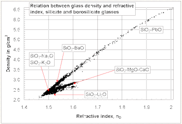
In general, the refractive index of a glass increases with its density. However, there does not exist an overall linear relationship between the refractive index and the density for all silicate and borosilicate glasses. A relatively high refractive index and low density can be obtained with glasses containing light metal oxides such as Li2O and MgO, while the opposite trend is observed with glasses containing PbO and BaO as seen in the diagram at the right.
Many oils (such as olive oil) and ethanol are examples of liquids that are more refractive, but less dense, than water, contrary to the general correlation between density and refractive index.
For air, n - 1 is proportional to the density of the gas as long as the chemical composition does not change.[51] This means that it is also proportional to the pressure and inversely proportional to the temperature for ideal gases.
Group index edit
Sometimes, a "group velocity refractive index", usually called the group index is defined:[citation needed]


When the refractive index of a medium is known as a function of the vacuum wavelength (instead of the wavelength in the medium), the corresponding expressions for the group velocity and index are (for all values of dispersion)[52]

Velocity, momentum, and polarizability edit
As shown in the Fizeau experiment, when light is transmitted through a moving medium, its speed relative to an observer traveling with speed v in the same direction as the light is:

The momentum of photons in a medium of refractive index n is a complex and controversial issue with two different values having different physical interpretations.[53]
The refractive index of a substance can be related to its polarizability with the Lorentz–Lorenz equation or to the molar refractivities of its constituents by the Gladstone–Dale relation.
Refractivity edit
In atmospheric applications, refractivity is defined as N = n – 1, often rescaled as either[54] N = 106 (n – 1)[55][56] or N = 108 (n – 1);[57] the multiplication factors are used because the refractive index for air, n deviates from unity by at most a few parts per ten thousand.
Molar refractivity, on the other hand, is a measure of the total polarizability of a mole of a substance and can be calculated from the refractive index as

Nonscalar, nonlinear, or nonhomogeneous refraction edit
So far, we have assumed that refraction is given by linear equations involving a spatially constant, scalar refractive index. These assumptions can break down in different ways, to be described in the following subsections.
Birefringence edit
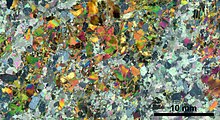
In some materials, the refractive index depends on the polarization and propagation direction of the light.[58] This is called birefringence or optical anisotropy.
In the simplest form, uniaxial birefringence, there is only one special direction in the material. This axis is known as the optical axis of the material.[1]: 230 Light with linear polarization perpendicular to this axis will experience an ordinary refractive index no while light polarized in parallel will experience an extraordinary refractive index ne.[1]: 236 The birefringence of the material is the difference between these indices of refraction, Δn = ne − no.[1]: 237 Light propagating in the direction of the optical axis will not be affected by the birefringence since the refractive index will be no independent of polarization. For other propagation directions the light will split into two linearly polarized beams. For light traveling perpendicularly to the optical axis the beams will have the same direction.[1]: 233 This can be used to change the polarization direction of linearly polarized light or to convert between linear, circular, and elliptical polarizations with waveplates.[1]: 237
Many crystals are naturally birefringent, but isotropic materials such as plastics and glass can also often be made birefringent by introducing a preferred direction through, e.g., an external force or electric field. This effect is called photoelasticity, and can be used to reveal stresses in structures. The birefringent material is placed between crossed polarizers. A change in birefringence alters the polarization and thereby the fraction of light that is transmitted through the second polarizer.
In the more general case of trirefringent materials described by the field of crystal optics, the dielectric constant is a rank-2 tensor (a 3 by 3 matrix). In this case the propagation of light cannot simply be described by refractive indices except for polarizations along principal axes.
Nonlinearity edit
The strong electric field of high intensity light (such as the output of a laser) may cause a medium's refractive index to vary as the light passes through it, giving rise to nonlinear optics.[1]: 502 If the index varies quadratically with the field (linearly with the intensity), it is called the optical Kerr effect and causes phenomena such as self-focusing and self-phase modulation.[1]: 264 If the index varies linearly with the field (a nontrivial linear coefficient is only possible in materials that do not possess inversion symmetry), it is known as the Pockels effect.[1]: 265
Inhomogeneity edit
If the refractive index of a medium is not constant but varies gradually with the position, the material is known as a gradient-index (GRIN) medium and is described by gradient index optics.[1]: 273 Light traveling through such a medium can be bent or focused, and this effect can be exploited to produce lenses, some optical fibers, and other devices. Introducing GRIN elements in the design of an optical system can greatly simplify the system, reducing the number of elements by as much as a third while maintaining overall performance.[1]: 276 The crystalline lens of the human eye is an example of a GRIN lens with a refractive index varying from about 1.406 in the inner core to approximately 1.386 at the less dense cortex.[1]: 203 Some common mirages are caused by a spatially varying refractive index of air.
Refractive index measurement edit
Homogeneous media edit
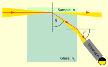
The refractive index of liquids or solids can be measured with refractometers. They typically measure some angle of refraction or the critical angle for total internal reflection. The first laboratory refractometers sold commercially were developed by Ernst Abbe in the late 19th century.[59] The same principles are still used today. In this instrument, a thin layer of the liquid to be measured is placed between two prisms. Light is shone through the liquid at incidence angles all the way up to 90°, i.e., light rays parallel to the surface. The second prism should have an index of refraction higher than that of the liquid, so that light only enters the prism at angles smaller than the critical angle for total reflection. This angle can then be measured either by looking through a telescope,[clarification needed] or with a digital photodetector placed in the focal plane of a lens. The refractive index n of the liquid can then be calculated from the maximum transmission angle θ as n = nG sin θ, where nG is the refractive index of the prism.[60]
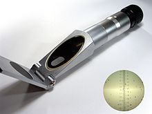
This type of device is commonly used in chemical laboratories for identification of substances and for quality control. Handheld variants are used in agriculture by, e.g., wine makers to determine sugar content in grape juice, and inline process refractometers are used in, e.g., chemical and pharmaceutical industry for process control.
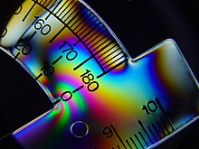
In gemology, a different type of refractometer is used to measure the index of refraction and birefringence of gemstones. The gem is placed on a high refractive index prism and illuminated from below. A high refractive index contact liquid is used to achieve optical contact between the gem and the prism. At small incidence angles most of the light will be transmitted into the gem, but at high angles total internal reflection will occur in the prism. The critical angle is normally measured by looking through a telescope.[61]
Refractive index variations edit

Unstained biological structures appear mostly transparent under bright-field microscopy as most cellular structures do not attenuate appreciable quantities of light. Nevertheless, the variation in the materials that constitute these structures also corresponds to a variation in the refractive index. The following techniques convert such variation into measurable amplitude differences:
To measure the spatial variation of the refractive index in a sample phase-contrast imaging methods are used. These methods measure the variations in phase of the light wave exiting the sample. The phase is proportional to the optical path length the light ray has traversed, and thus gives a measure of the integral of the refractive index along the ray path. The phase cannot be measured directly at optical or higher frequencies, and therefore needs to be converted into intensity by interference with a reference beam. In the visual spectrum this is done using Zernike phase-contrast microscopy, differential interference contrast microscopy (DIC), or interferometry.
Zernike phase-contrast microscopy introduces a phase shift to the low spatial frequency components of the image with a phase-shifting annulus in the Fourier plane of the sample, so that high-spatial-frequency parts of the image can interfere with the low-frequency reference beam. In DIC the illumination is split up into two beams that are given different polarizations, are phase shifted differently, and are shifted transversely with slightly different amounts. After the specimen, the two parts are made to interfere, giving an image of the derivative of the optical path length in the direction of the difference in the transverse shift.[46] In interferometry the illumination is split up into two beams by a partially reflective mirror. One of the beams is let through the sample before they are combined to interfere and give a direct image of the phase shifts. If the optical path length variations are more than a wavelength the image will contain fringes.
There exist several phase-contrast X-ray imaging techniques to determine 2D or 3D spatial distribution of refractive index of samples in the X-ray regime.[62]
Applications edit
The refractive index is an important property of the components of any optical instrument. It determines the focusing power of lenses, the dispersive power of prisms, the reflectivity of lens coatings, and the light-guiding nature of optical fiber. Since the refractive index is a fundamental physical property of a substance, it is often used to identify a particular substance, confirm its purity, or measure its concentration. The refractive index is used to measure solids, liquids, and gases. Most commonly it is used to measure the concentration of a solute in an aqueous solution. It can also be used as a useful tool to differentiate between different types of gemstone, due to the unique chatoyance each individual stone displays. A refractometer is the instrument used to measure the refractive index. For a solution of sugar, the refractive index can be used to determine the sugar content (see Brix).
See also edit
Footnotes edit
- ^ One consequence of the real part of n being less than unity is that it implies that the phase velocity inside the material, c/n, is larger than the velocity of light, c. This does not, however, violate the law of relativity, which requires that only signals carrying information do not travel faster than c. Such signals move with the group velocity, not with the phase velocity, and it can be shown that the group velocity is in fact less than c.[20]
References edit
- ^ a b c d e f g h i j k l m n o p q r Hecht, Eugene (2002). Optics. Addison-Wesley. ISBN 978-0-321-18878-6.
- ^ a b Attwood, David (1999). Soft X-rays and extreme ultraviolet radiation: principles and applications. Cambridge University Press. p. 60. ISBN 978-0-521-02997-1.
- ^ Kinsler, Lawrence E. (2000). Fundamentals of Acoustics. John Wiley. p. 136. ISBN 978-0-471-84789-2.
- ^ Young, Thomas (1807). A course of lectures on natural philosophy and the mechanical arts. J. Johnson. p. 413.
- ^ Newton, Isaac (1730). Opticks: Or, A Treatise of the Reflections, Refractions, Inflections and Colours of Light. William Innys at the West-End of St. Paul's. p. 247.
- ^ Hauksbee, Francis (1710). "A Description of the Apparatus for Making Experiments on the Refractions of Fluids". Philosophical Transactions of the Royal Society of London. 27 (325–336): 207. doi:10.1098/rstl.1710.0015. S2CID 186208526.
- ^ Hutton, Charles (1795). Philosophical and mathematical dictionary. p. 299. Archived from the original on 2017-02-22.
- ^ von Fraunhofer, Joseph (1817). "Bestimmung des Brechungs und Farbenzerstreuungs Vermogens verschiedener Glasarten" [Determination of the Refraction and Color Scattering Power of Different Types of Glass]. Denkschriften der Königlichen Akademie der Wissenschaften zu München [Journal of the Royal Academy of Sciences in Munich] (in German). 5: 208. Archived from the original on 2017-02-22. Exponent des Brechungsverhältnisses is index of refraction
- ^ Brewster, David (1815). "On the structure of doubly refracting crystals". Philosophical Magazine. 45 (202): 126. doi:10.1080/14786441508638398. Archived from the original on 2017-02-22.
- ^ Herschel, John F. W. (1828). On the Theory of Light. p. 368. Archived from the original on 2015-11-24.
- ^ Malitson (1965). "Refractive Index Database". refractiveindex.info. Retrieved June 20, 2018.
- ^ Faick, C. A.; Finn, A. N. (July 1931). "The Index of Refraction of Some Soda-Lime-Silica Glasses as a Function of the Composition" (PDF). National Institute of Standards and Technology. Archived (PDF) from the original on December 30, 2016. Retrieved 11 December 2016.
- ^ Sultanova, N.; Kasarova, S.; Nikolov, I. (October 2009). "Dispersion Properties of Optical Polymers". Acta Physica Polonica A. 116 (4): 585–587. Bibcode:2009AcPPA.116..585S. doi:10.12693/APhysPolA.116.585.
- ^ Tapping, J.; Reilly, M. L. (1 May 1986). "Index of refraction of sapphire between 24 and 1060°C for wavelengths of 633 and 799 nm". Journal of the Optical Society of America A. 3 (5): 610. Bibcode:1986JOSAA...3..610T. doi:10.1364/JOSAA.3.000610.
- ^ "Forensic Science Communications, Glass Refractive Index Determination". FBI Laboratory Services. Archived from the original on 2014-09-10. Retrieved 2014-09-08.
- ^ Tabata, M.; et al. (2005). Development of Silica Aerogel with Any Density (PDF). IEEE Nuclear Science Symposium Conference Record. Vol. 2. pp. 816–818. doi:10.1109/NSSMIC.2005.1596380. ISBN 978-0-7803-9221-2. S2CID 18187536. Archived from the original (PDF) on 2013-05-18.
- ^ Sadayori, Naoki; Hotta, Yuji (2004). "Polycarbodiimide having high index of refraction and production method thereof". US Patent Office. US patent 2004/0158021 A1 – via Google Patents.
- ^ Tosi, Jeffrey L., article on Common Infrared Optical Materials in the Photonics Handbook, accessed on 2014-09-10
- ^ Yue, Zengji; Cai, Boyuan; Wang, Lan; Wang, Xiaolin; Gu, Min (2016-03-01). "Intrinsically core-shell plasmonic dielectric nanostructures with ultrahigh refractive index". Science Advances. 2 (3): e1501536. Bibcode:2016SciA....2E1536Y. doi:10.1126/sciadv.1501536. ISSN 2375-2548. PMC 4820380. PMID 27051869.
- ^ a b Als-Nielsen, J.; McMorrow, D. (2011). Elements of Modern X-ray Physics. Wiley-VCH. p. 25. ISBN 978-0-470-97395-0.
- ^ a b Gullikson, Eric. "X-Ray interactions with matter". Optical constants. The Center for X-Ray Optics. Lawrence Berkeley Laboratory. Archived from the original on 2011-08-27. Retrieved 2011-08-30.
- ^ Lied, Finn (1967). High Frequency Radio Communications with Emphasis on Polar Problems. The Advisory Group for Aerospace Research and Development. pp. 1–7.
- ^ Veselago, V. G. (1968). "The electrodynamics of substances with simultaneously negative values of ε and μ". Soviet Physics Uspekhi. 10 (4): 509–514. Bibcode:1968SvPhU..10..509V. doi:10.1070/PU2003v046n07ABEH001614. S2CID 250862458.
- ^ Pendry, J. B.; Schurig, D.; Smith, D. R. (Dec 8, 2009). "Electromagnetic compression apparatus, methods and systems". US Patent Office. US Patent 7629941 – via Google Patents.
- ^ Shalaev, V. M. (2007). "Optical negative-index metamaterials". Nature Photonics. 1 (1): 41–48. Bibcode:2007NaPho...1...41S. doi:10.1038/nphoton.2006.49. S2CID 170678.
- ^ a b Feynman, Richard P. (2011). Mainly Mechanics, Radiation, and Heat. Feynman Lectures on Physics. Vol. 1 (The New Millenium ed.). Basic Books. ISBN 978-0-465-02493-3.
- ^ a b Paschotta, Rüdiger. "Chromatic Dispersion". RP Photonics Encyclopedia. Archived from the original on 2015-06-29. Retrieved 2023-08-13.
- ^ a b Nave, Carl R. (2000). "Dispersion". HyperPhysics. Department of Physics and Astronomy, Georgia State University. Archived from the original on 2014-09-24. Retrieved 2023-08-13.
- ^ Paschotta, Rüdiger. "Sellmeier formula". RP Photonics Encyclopedia. Archived from the original on 2015-03-19. Retrieved 2014-09-08.
- ^ Schott Company. "Interactive Abbe Diagram". Schott.com. Retrieved 2023-08-13.
- ^ Ohara Corporation. "Optical Properties". Oharacorp.com. Retrieved 2022-08-15.
- ^ Hoya Group. "Optical Properties". Hoya Group Optics Division. Retrieved 2023-08-13.
- ^ Lentes, Frank-Thomas; Clement, Marc K. Th.; Neuroth, Norbert; Hoffmann, Hans-Jürgen; Hayden, Yuiko T.; Hayden, Joseph S.; Kolberg, Uwe; Wolff, Silke (1998). "Optical Properties". In Bach, Hans; Neuroth, Norbert (eds.). The Properties of Optical Glass. Schott Series on Glass and Glass Ceramics. p. 30. doi:10.1007/978-3-642-57769-7. ISBN 978-3-642-63349-2.
- ^ Krey, Stefan; Off, Dennis; Ruprecht, Aiko (2014-03-08). "Measuring the Refractive Index with Precision Goniometers: A Comparative Study". In Soskind, Yakov G.; Olson, Craig (eds.). Proc. SPIE 8992, Photonic Instrumentation Engineering. SPIE OPTO, 2014. Vol. 8992. San Francisco, California: SPIE. pp. 56–65. Bibcode:2014SPIE.8992E..0DK. doi:10.1117/12.2041760. S2CID 120544352.
- ^ Rupp, Fabian; Jedamzik, Ralf; Bartelmess, Lothar; Petzold, Uwe (2021-09-12). "The modern way of refractive index measurement of optical glass at SCHOTT". In Völkel, Reinhard; Geyl, Roland; Otaduy, Deitze (eds.). Optical Fabrication, Testing, and Metrology VII. Vol. 11873. SPIE. pp. 15–22. Bibcode:2021SPIE11873E..08R. doi:10.1117/12.2597023. ISBN 9781510645905. S2CID 240561530.
{{cite book}}:|journal=ignored (help) - ^ "Abbe Refractometer| ATAGO CO., LTD". www.atago.net. Retrieved 2022-08-15.
- ^ "Abbe Multi-Wavelength Refractometer". Nova-Tech International. Retrieved 2022-08-15.
- ^ Bach, Hans; Neuroth, Norbert, eds. (1998). The Properties of Optical Glass. Schott Series on Glass and Glass Ceramics. p. 267. doi:10.1007/978-3-642-57769-7. ISBN 978-3-642-63349-2.
- ^ Dresselhaus, M. S. (1999). "Solid State Physics Part II Optical Properties of Solids" (PDF). Course 6.732 Solid State Physics. MIT. Archived (PDF) from the original on 2015-07-24. Retrieved 2015-01-05.
- ^ R. Paschotta, article on optical thickness Archived 2015-03-22 at the Wayback Machine in the Encyclopedia of Laser Physics and Technology Archived 2015-08-13 at the Wayback Machine, accessed on 2014-09-08
- ^ R. Paschotta, article on refraction Archived 2015-06-28 at the Wayback Machine in the Encyclopedia of Laser Physics and Technology Archived 2015-08-13 at the Wayback Machine, accessed on 2014-09-08
- ^ a b c d Born, Max; Wolf, Emil (1999). Principles of Optics (7th expanded ed.). CUP Archive. p. 22. ISBN 978-0-521-78449-8.
- ^ Paschotta, R. "Total Internal Reflection". RP Photonics Encyclopedia. Archived from the original on 2015-06-28. Retrieved 2015-08-16.
- ^ Swenson, Jim (November 10, 2009). "Refractive Index of Minerals". Newton BBS / Argonne National Laboratory. US DOE. Archived from the original on May 28, 2010. Retrieved 2010-07-28.
Incorporates Public Domain material from the U.S. Department of Energy
- ^ Nave, Carl R. "Lens-makers' formula". HyperPhysics. Department of Physics and Astronomy. Georgia State University. Archived from the original on 2014-09-26. Retrieved 2014-09-08.
- ^ a b c Carlsson, Kjell (2007). Light microscopy (PDF) (Report). Archived (PDF) from the original on 2015-04-02. Retrieved 2015-01-02.
- ^ Bleaney, B.; Bleaney, B.I. (1976). Electricity and Magnetism (Third ed.). Oxford University Press. ISBN 978-0-19-851141-0.
- ^ Andrews, David L. (24 February 2015). Photonics, Volume 2: Nanophotonic Structures and Materials. John Wiley & Sons. p. 54. ISBN 978-1-118-22551-6.
- ^ Wooten, Frederick (1972). Optical Properties of Solids. New York City: Academic Press. p. 49. ISBN 978-0-12-763450-0.(online pdf) Archived 2011-10-03 at the Wayback Machine
- ^ "Calculation of the Refractive Index of Glasses". Statistical Calculation and Development of Glass Properties. Archived from the original on 2007-10-15.
- ^ Stone, Jack A.; Zimmerman, Jay H. (2011-12-28). "Index of refraction of air". Engineering metrology toolbox. National Institute of Standards and Technology (NIST). Archived from the original on 2014-01-11. Retrieved 2014-01-11.
- ^ Bor, Z.; Osvay, K.; Rácz, B.; Szabó, G. (1990). "Group refractive index measurement by Michelson interferometer". Optics Communications. 78 (2): 109–112. Bibcode:1990OptCo..78..109B. doi:10.1016/0030-4018(90)90104-2.
- ^ Milonni, Peter W.; Boyd, Robert W. (2010-12-31). "Momentum of Light in a Dielectric Medium". Advances in Optics and Photonics. 2 (4): 519. Bibcode:2010AdOP....2..519M. doi:10.1364/AOP.2.000519. ISSN 1943-8206.
- ^ Young, A.T. (2011). "Refractivity of Air". Archived from the original on 10 January 2015. Retrieved 31 July 2014.
- ^ Barrell, H.; Sears, J.E. (1939). "The refraction and dispersion of air for the visible spectrum". Philosophical Transactions of the Royal Society of London. A, Mathematical and Physical Sciences. 238 (786): 1–64. Bibcode:1939RSPTA.238....1B. doi:10.1098/rsta.1939.0004. JSTOR 91351.
- ^ Aparicio, Josep M.; Laroche, Stéphane (2 June 2011). "An evaluation of the expression of the atmospheric refractivity for GPS signals". Journal of Geophysical Research. 116 (D11): D11104. Bibcode:2011JGRD..11611104A. doi:10.1029/2010JD015214.
- ^ Ciddor, P.E. (1996). "Refractive index of air: New equations for the visible and near infrared". Applied Optics. 35 (9): 1566–1573. Bibcode:1996ApOpt..35.1566C. doi:10.1364/ao.35.001566. PMID 21085275.
- ^ R. Paschotta, article on birefringence Archived 2015-07-03 at the Wayback Machine in the Encyclopedia of Laser Physics and Technology Archived 2015-08-13 at the Wayback Machine, accessed on 2014-09-09
- ^ "The Evolution of the Abbe Refractometer". Humboldt State University, Richard A. Paselk. 1998. Archived from the original on 2011-06-12. Retrieved 2011-09-03.
- ^ "Refractometers and refractometry". Refractometer.pl. 2011. Archived from the original on 2011-10-20. Retrieved 2011-09-03.
- ^ "Refractometer". The Gemology Project. Archived from the original on 2011-09-10. Retrieved 2011-09-03.
- ^ Fitzgerald, Richard (July 2000). "Phase‐Sensitive X‐Ray Imaging". Physics Today. 53 (7): 23. Bibcode:2000PhT....53g..23F. doi:10.1063/1.1292471. S2CID 121322301.
External links edit
- NIST calculator for determining the refractive index of air
- Dielectric materials
- Science World
- Filmetrics' online database Free database of refractive index and absorption coefficient information
- RefractiveIndex.INFO Refractive index database featuring online plotting and parameterisation of data
- LUXPOP Archived 2013-09-07 at the Wayback Machine Thin film and bulk index of refraction and photonics calculations
- The Feynman Lectures on Physics Vol. II Ch. 32: Refractive Index of Dense Materials