


Summary
The South African Railways Class 6E of 1970 was an electric locomotive.
| South African Class 6E | |||||||||||||||||||||||||||||||||||||||||||||||||||||||||||||
|---|---|---|---|---|---|---|---|---|---|---|---|---|---|---|---|---|---|---|---|---|---|---|---|---|---|---|---|---|---|---|---|---|---|---|---|---|---|---|---|---|---|---|---|---|---|---|---|---|---|---|---|---|---|---|---|---|---|---|---|---|---|
 E1221 approaching Bellville station in September 2006 | |||||||||||||||||||||||||||||||||||||||||||||||||||||||||||||
| |||||||||||||||||||||||||||||||||||||||||||||||||||||||||||||
| |||||||||||||||||||||||||||||||||||||||||||||||||||||||||||||
| |||||||||||||||||||||||||||||||||||||||||||||||||||||||||||||
| |||||||||||||||||||||||||||||||||||||||||||||||||||||||||||||
In 1970 and 1971, the South African Railways placed eighty Class 6E mainline electric locomotives with a Bo-Bo wheel arrangement in service. Two more were built for Iscor for use at the Sishen mine.[1]
Manufacturer edit
The 3 kV DC Class 6E electric locomotive was designed and built for the South African Railways (SAR) in 1970 by Union Carriage & Wagon (UCW) in Nigel, Transvaal, with the electrical equipment being supplied by Associated Electrical Industries and English Electric.[2][3]
Original operators edit
South African Railways edit
Eighty units were delivered to the SAR in 1970 and 1971, numbered in the range from E1146 to E1225. UCW did not allocate builder's or works numbers to the locomotives it built for the SAR, but used the SAR unit numbers for their record keeping.[1]
Sishen mine edit
In 1970, two Class 6E locomotives were also built new by UCW for Iscor (now Kumba), for use at the Sishen mine in the Northern Cape. Numbered Iscor F221.01 and F221.02, these two were allocated UCW works numbers 6E.58 and 6E.59 respectively.[2]
Characteristics edit
Orientation edit
These dual cab locomotives had a roof access ladder on one side only, just to the right of the cab access door. The roof access ladder end was marked as the no. 2 end. A corridor along the centre of the locomotive connected the cabs, which were identical apart from the fact that the handbrake was located in cab 2. A pantograph hook stick was stowed in a tube mounted below the bottom edge of the locomotive body on the roof access ladder side. The units had one square and two rectangular access panels along the lower half of the body on the roof access ladder side and only one square access panel on the opposite side. Three footsteps were mounted on the bogie directly below each side door.[1]
The Class 6E was delivered in the new body shape with squared corners that had been introduced part-way through the construction of the Class 5E1, Series 5 and was equipped with double sealed-beam automobile headlamps. The body dimensions were the same as that of the later models of the Class 5E1, Series 5 and the most visually obvious external difference was the replacement of the three small vertically arranged grilles to the right of centre on each side of the Classes 5E and 5E1 with a larger double grille on each side of the Class 6E. In respect of the coachwork, the Class 6E was identical to its immediate predecessor, the Class 6E1, Series 1, while its bogies were identical to those of the Class 5E1.[1][4]
Bogies edit
Compared to the Class 5E1, the Class 6E had improved type AEI-283AZ traction motors, particularly with regard to the insulation of the windings. This resulted in a continuous power output of 563 kilowatts (755 horsepower) per traction motor and a total continuous power output of 2,252 kilowatts (3,020 horsepower) per locomotive, compared to the 364 kilowatts (488 horsepower) per traction motor and 1,456 kilowatts (1,953 horsepower) total of the Class 5E1.[5]
To ensure the maximum transfer of power to the rails without causing wheel-slip with these more powerful traction motors, the Class 6E was built with carefully designed weight transfer air bellows between the bogies and the frames. This reduced the adhesion of the leading bogie and increased that of the trailing bogie by as much as 15% upon starting off. This feature was controlled by electronic wheel-slip detection devices and an electric weight transfer relay, which reduced the anchor current to the leading bogie by as much as 50A in notches 2 to 16.[5][6]
Operation edit
Startup edit
When there was no compressed air in the unit's system to raise a pantograph to start up, a pantograph hook stick was used to manually raise the pantograph. This started the high voltage motor which drove the auxiliary alternator to supply 110 V power to start the compressor and power other control circuits. Once there was enough main air pressure to keep the pantograph in the raised position, the pantograph hook stick could be removed.[7]
The unit was controlled via resistors over which the voltage was dropped in a configuration of series and parallel electrical circuits. The circuit breakers that switched these circuits worked under very high power and voltage and were therefore all pneumatically operated for insulation purposes. Compressed air was required to open or close the switch actions and air was also used for the weak-field Cam Switch that also switched under very high currents.[7]
Running edit
Upon starting off and in the low notches, the major part of the voltage was dropped over the banks of resistors and all four traction motors were in series. The blowers which accelerated the dissipation of heat in the resistor banks gave the Classes 6E and 6E1 their very distinctive sound, a deep and loud whine when power was applied.[6][7]
As the driver notched up, some of the resistor banks were cut out via the pneumatically operated switches and the voltage increased across the traction motors. As the driver notched higher, more resistors were cut out and more power was developed by the traction motors. At around 22 to 28 kilometres per hour (14 to 17 miles per hour) the unit switched to a parallel combination where the two traction motors per bogie were in a series electrical circuit while the two bogies were in a parallel electrical circuit. Eventually, when all resistors were cut out, the unit was operating in full-field.[7]
When the traction motors were operated in full-field, be it in series or parallel mode, they were performing at maximum power for normal operation. To increase the speed at this point, if necessary, higher power output was required from the traction motors. The only way to increase power was to force a higher current flow. To accomplish this, the weak-field cam switch switched resistance in parallel with the field coils, which reduced the overall resistance of the field coils. This increased the magnetic flux and more power was generated by the traction motors, but only over short periods.[7]
Brakes edit
The unit itself used air brakes, but it was equipped to operate trains with air or vacuum brakes. The brake system would be set up for either air or vacuum train working by means of a turning switch on the driver's brake valve and by pre-setting the appropriate brake valves in the corridor.[8]
While hauling a vacuum braked train, the unit's air brake system would be disabled and the train would be controlled by using the train brakes alone to slow down and stop. While hauling an air braked train, on the other hand, the unit's brakes would engage along with the train brakes. While working either type of train downgrade, the unit's regenerative braking system would also work in conjunction with the train brakes.[8]
Unlike the Classes 5E and 5E1 whose air brakes could be applied independently on each bogie when the locomotive was stopped, the air brakes on both bogies would be applied together on the Classes 6E and 6E1. The handbrake or parking brake, located in cab 2, only operated on the unit's last axle, or no. 7 and 8 wheels.[8]
Service edit
The Class 6E saw service all over both 3 kV DC mainline and branch line networks.[2]
Cape Western network edit
The smaller network is the Cape Western mainline between Cape Town and Beaufort West, with the units based at the Bellville Depot in Cape Town.[2]
Northern network edit
The larger network covers portions of the Northern Cape, the Free State, Natal, Gauteng, North West and Mpumalanga, the main routes in this vast area being as follows:[2]
- From Johannesburg in Gauteng via Kimberley to Hotazel in the Northern Cape.
- From Johannesburg via Kroonstad to Bloemfontein in the Free State.
- From Johannesburg to Durban in Natal.
- From Johannesburg via Pretoria in Gauteng and Witbank in Mpumalanga to Komatipoort on the Mozambique border as well as to Derwent and Roossenekal.
- From Johannesburg via Springs to Witbank.
- From Johannesburg via Coligny to Lichtenburg.
- From Durban in Natal to Empangeni in the north and Port Shepstone in the south.
- From Ermelo to Ogies and Wonderfontein in Mpumalanga.
- From Kroonstad in the Free State via Bethlehem and Ladysmith to Vryheid in Natal.
The electric units allocated to depots within this larger network were largely pooled and the Class 6E served in the same locomotive pool alongside the Class 6E1 family. They could operate anywhere in the network as required by the Operating Department, but they returned to their home depots for maintenance every twenty-eight days.[2]
By 2010 a large number of the Class 6E were still in service and allocated to depots in both networks, but by 2015 Class 6Es were rarely seen, most having been withdrawn and replaced by rebuilt Class 18E locomotives.[2]
Liveries edit
The whole Class was delivered in the SAR Gulf Red livery with signal red cowcatchers, yellow whiskers and with the number plates on the sides mounted on three-stripe yellow wings. In the 1990s many of the units began to be repainted in the Spoornet orange livery with a yellow and blue chevron pattern on the cowcatchers. By 2000 they were all repainted in either this new livery or the similar Spoornet maroon livery.[9]
In the SAR and Spoornet eras, many selected electric locomotives and some diesel-electrics were painted blue for use with the Blue Train, but without altering the layout of the various paint schemes in use at the time. Blue Train locomotives were therefore blue with yellow whiskers in the SAR era, blue with the Spoornet logo and "SPOORNET" in Spoornet's orange era, and blue with the Spoornet logo but without "SPOORNET" in Spoornet's maroon era. Later, in Spoornet's blue era, there was no need for a separate Blue Train livery.[2][10][11]
Unofficial renumbering edit
The Cape Western region usually had eight electric locomotives in a blue livery on its roster to be used with the Blue Train when required. When the Cape Western's Series 1 Class 5E1s in Blue Train service, numbers E441 to E448, were withdrawn from mainline passenger service during the 1990s, eight Class 6E1, Series 8 units, numbers E1950 to E1957, were painted blue with yellow whiskers for use with the Blue Train. After four of these blue Class 6E1 locomotives were damaged in a collision between two Trans-Karoo passenger trains at Gouda in April 1997, the Bellville Depot was authorised to repaint eight Class 6E locomotives in Spoornet's orange era Blue Train livery. The authorisation was given for numbers E1171 to E1178.[2][5]
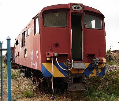
In the process three locomotives, which were considered to be "better" candidates, numbers E1146, E1157 and E1223, unofficially exchanged unit numbers with numbers E1172, E1177 and E1174 respectively. Evidence of the unofficial number change was still visible years later in the slightly different shade of orange around the unit numbers on the sides of the orange numbers E1146, E1157 and E1223, as illustrated.[2]
-
 No. E1172 posing as no. E1146, Bellville Depot, 28 March 2009
 -
 No. E1174 posing as no. E1223, Stikland, Cape Town, 29 March 2006
 -
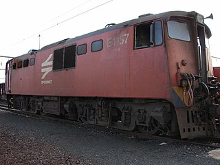 No. E1177 posing as no. E1157, Beaufort West, 1 May 2006


Illustration edit
The Class 6Es for the SAR were delivered in the Gulf Red livery with yellow whiskers, but all of them have since been repainted in various Spoornet liveries. The main picture shows no. E1221 in the Spoornet orange livery, while other liveries which were applied to Class 6E locomotives are illustrated below. No Class 6E locomotive ever served in the older SAR blue and yellow whiskers livery for the Blue Train and no. E1220 as shown here, was painted in that livery only after it was scrapped and its shell was converted to a braai facility at the Bellville locomotive depot.[2]
-
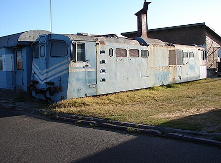 No. E1220's shell, repainted in SAR blue and whiskers livery and used as a clubhouse at Bellville Depot, 28 March 2009
 -

-
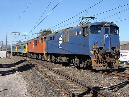 No. E1175 in Spoornet's orange era Blue Train livery, approaching Bellville, Cape Town, 19 March 2007
 -
 No. E1213 in Spoornet's maroon livery at Koedoespoort, Gauteng, 9 October 2009


References edit
- ^ a b c d South African Railways Index and Diagrams Electric and Diesel Locomotives, 610mm and 1065mm Gauges, Ref LXD 14/1/100/20, 28 January 1975, as amended
- ^ a b c d e f g h i j k Middleton, John N. (2002). Railways of Southern Africa Locomotive Guide - 2002 (as amended by Combined Amendment List 4, January 2009) (2nd, Dec 2002 ed.). Herts, England: Beyer-Garratt Publications. pp. 49–51, 54, 63.
- ^ "UCW – Electric locomotives" (PDF). The UCW Partnership. Archived from the original (PDF) on 12 October 2007. Retrieved 30 September 2010.
- ^ Soul of A Railway, System 7, Western Transvaal, based in Johannesburg, Part 20: Natalspruit to Vereeniging, Part 3. Caption 30. (Accessed on 29 April 2017)
- ^ a b c Paxton, Leith; Bourne, David (1985). Locomotives of the South African Railways (1st ed.). Cape Town: Struik. pp. 128–129. ISBN 0869772112.
- ^ a b Dulez, Jean A. (2012). Railways of Southern Africa 150 Years (Commemorating One Hundred and Fifty Years of Railways on the Sub-Continent – Complete Motive Power Classifications and Famous Trains – 1860–2011) (1st ed.). Garden View, Johannesburg, South Africa: Vidrail Productions. p. 295. ISBN 9 780620 512282.
- ^ a b c d e Operation – South African Classes 6E, 6E1, 16E, 17E and 18E
- ^ a b c Information obtained from Transnet engineers and drivers.
- ^ Soul of A Railway, System 7, Western Transvaal, based in Johannesburg, Part 9. South-Eastwards as far as Volksrust (2nd part) by Les Pivnic. Caption 4. (Accessed on 11 April 2017)
- ^ No. E1973 in blue based on Spoornet’s orange livery.
- ^ No. E1951 in blue based on Spoornet’s maroon livery.