


Summary
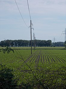
A utility pole is a column or post, usually made out of wood or aluminum alloy,[1] used to support overhead power lines and various other public utilities, such as electrical cable, fiber optic cable, and related equipment such as transformers and street lights. It can be referred to as a transmission pole, telephone pole, telecommunication pole, power pole,[2] hydro pole,[3] telegraph pole, or telegraph post, depending on its application. A Stobie pole is a multi-purpose pole made of two steel joists held apart by a slab of concrete in the middle, generally found in South Australia.

Electrical wires and cables are routed overhead on utility poles as an inexpensive way to keep them insulated from the ground and out of the way of people and vehicles.[4] Utility poles can be made of wood, metal, concrete, or composites like fiberglass. They are used for two different types of power lines: sub transmission lines, which carry higher voltage power between substations, and distribution lines, which distribute lower voltage power to customers.
The first poles were used in 1843 by telegraph pioneer William Fothergill Cooke, who used them on a line along the Great Western Railway. Utility poles were first used in the mid-19th century in America with telegraph systems, starting with Samuel Morse, who attempted to bury a line between Baltimore and Washington, D.C., but moved it above ground when this system proved faulty. Today, underground distribution lines are increasingly used as an alternative to utility poles in residential neighborhoods, due to poles' perceived ugliness, as well as safety concerns in areas with large amounts of snow or ice build up.
Use edit
Utility poles are commonly used to carry two types of electric power lines:[5] distribution lines (or "feeders") and sub transmission lines. Distribution lines carry power from local substations to customers. They generally carry voltages from 4.6 to 33 kilovolts (kV) for distances up to 30 mi (50 km), and include transformers to step the voltage down from the primary voltage to the lower secondary voltage used by the customer. A service drop carries this lower voltage to the customer's premises.
Subtransmission lines carry higher voltage power from regional substations to local substations. They usually carry 46 kV, 69 kV, or 115 kV for distances up to 60 mi (100 km). 230 kV lines are often supported on H-shaped towers made with two or three poles. Transmission lines carrying voltages of above 230 kV are usually not supported by poles, but by metal pylons (known as transmission towers in the US).
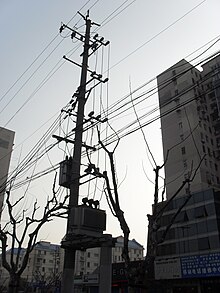
For economic or practical reasons, such as to save space in urban areas, a distribution line is often carried on the same poles as a sub transmission line but mounted under the higher voltage lines; a practice called "underbuild". Telecommunication cables are usually carried on the same poles that support power lines; poles shared in this fashion are known as joint-use poles, but may have their own dedicated poles.
Description edit
The standard utility pole in the United States is about 35 ft (10 m) tall and is buried about 6 ft (2 m) in the ground.[6] However, poles can reach heights of 120 ft (40 m) or more to satisfy clearance requirements. They are typically spaced about 125 ft (40 m) apart in urban areas, or about 300 ft (100 m) in rural areas, but distances vary widely based on terrain. Joint-use poles are usually owned by one utility, which leases space on it for other cables. In the United States, the National Electrical Safety Code, published by the Institute of Electrical and Electronics Engineers (IEEE) (not to be confused with the National Electrical Code published by the National Fire Protection Association [NFPA]), sets the standards for construction and maintenance of utility poles and their equipment.
Pole materials edit
Most utility poles are made of wood, pressure-treated with some type of preservative for protection against rot, fungi and insects. Southern yellow pine is the most widely used species in the United States; however, many species of long straight trees are used to make utility poles, including Douglas fir, jack pine, lodgepole pine, western red cedar, and Pacific silver fir.
Traditionally, the preservative used was creosote, but due to environmental concerns, alternatives such as pentachlorophenol, copper naphthenate and borates are becoming widespread in the United States. In the United States, standards for wood preservative materials and wood preservation processes, along with test criteria, are set by ANSI, ASTM, and American Wood Protection Association (AWPA) specifications. Despite the preservatives, wood poles decay and have a life of approximately 25 to 50 years depending on climate and soil conditions, therefore requiring regular inspection and remedial preservative treatments.[7][8][9] Woodpecker damage to wood poles is the most significant cause of pole deterioration in the U.S.[10]
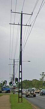
Other common utility pole materials are aluminum, steel and concrete, with composites (such as fiberglass[citation needed]) also becoming more prevalent.[11] One particular patented utility pole variant used in Australia is the Stobie pole, made up of two vertical steel posts with a slab of concrete between them.
In southern Switzerland along various lakes, telephone poles are made of granite. Starting in the early 1900s, these 5 m (20 ft) poles were originally used for telegraph wires and later for telephone wires. Because they are made of granite, the poles last indefinitely.[12]
Power distribution wires and equipment edit

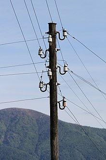
On poles carrying both electrical and communications wiring, the electric power distribution lines and associated equipment are mounted at the top of the pole above the communication cables, for safety. The vertical space on the pole reserved for this equipment is called the supply space.[6] The wires themselves are usually uninsulated, and supported by insulators, commonly mounted on a horizontal beam (crossarm). Power is transmitted using the three-phase system, with three wires, or phases, labeled "A", "B", and "C".
Sub transmission lines comprise only these 3 wires, plus sometimes an overhead ground wire (OGW), also called a "static line" or a "neutral", suspended above them. The OGW acts like a lightning rod, providing a low resistance path to ground thus protecting the phase conductors from lightning.
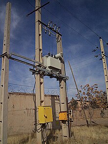
Distribution lines use two systems, either grounded-wye ("Y" on electrical schematics) or delta (Greek letter "Δ" on electrical schematics). A delta system requires only a conductor for each of the three phases. A grounded-wye system requires a fourth conductor, the neutral, whose source is the center of the "Y" and is grounded. However, "spur lines" branching off the main line to provide power to side streets often carry only one or two phase wires, plus the neutral. A wide range of standard distribution voltages are used, from 2,400 V to 34,500 V. On poles near a service drop, there is a pole-mounted step-down distribution transformer to transform the high distribution voltage to the lower secondary voltage provided to the customer. In North America, service drops provide 240/120 V split-phase power for residential and light commercial service, using cylindrical single-phase transformers. In Europe and most other countries, 230 V three phase (230Y400) service drops are used. The transformer's primary is connected to the distribution line through protective devices called fuse cutouts. In the event of an overload, the fuse melts and the device pivots open to provide a visual indication of the problem. They can also be opened manually by linemen using a long insulated rod called a hot stick to disconnect the transformer from the line.
The pole may be grounded with a heavy bare copper or copper-clad steel wire running down the pole, attached to the metal pin supporting each insulator, and at the bottom connected to a metal rod driven into the ground. Some countries ground every pole while others only ground every fifth pole and any pole with a transformer on it. This provides a path for leakage currents across the surface of the insulators to get to ground, preventing the current from flowing through the wooden pole which could cause a fire or shock hazard.[5][6] It provides similar protection in case of flashovers and lightning strikes. A surge arrester (also called a lightning arrester) may also be installed between the line (ahead of the cutout) and the ground wire for lightning protection. The purpose of the device is to conduct extremely high voltages present on the line directly to ground.
If uninsulated conductors touch due to wind or fallen trees, the resultant sparks can start wildfires. To reduce this problem, aerial bundled conductors are being introduced.
Communication cables edit
The communications cables are attached below the electric power lines, in a vertical space along the pole designated the communications space.[6] The communications space is separated from the lowest electrical conductor by the communication worker safety zone, which provides room for workers to maneuver safely while servicing the communication cables, avoiding contact with the power lines.[6]
The most common communication cables found on utility poles are copper or fibre-optic cable (FOC) for telephone lines and coaxial cable for cable television (CATV). Coaxial or optical fibre cables linking computer networks are also increasingly found on poles in urban areas. The cable linking the telephone exchange to local customers is a thick cable lashed to a thin supporting cable, containing hundreds of twisted pair subscriber lines. Each twisted pair line provides a single telephone circuit or local loop to a customer. There may also be FOCs interconnecting telephone exchanges. Like electrical distribution lines, communication cables connect to service drops when used to provide local service to customers.
Other equipment edit
Utility poles may also carry other equipment such as street lights, supports for traffic lights and overhead wires for electric trolleys, and cellular network antennas. They can also carry fixtures and decorations specific for certain holidays or events specific to the city where they are located.
Solar panels mounted on utility poles may power auxiliary equipment where the expense of a power line connection is unwanted.
Streetlights and holiday fixtures are powered directly from secondary distribution.
Pole attachment hardware edit

The primary purpose of pole attachment hardware is to secure the cable and associated aerial plant facilities to poles and to help facilitate necessary plant rearrangements. An aerial plant network requires high-quality reliable hardware to
- Structurally support the distribution cable plant
- Provide directional guying to accommodate lateral stresses created on the pole by pole line configurations and pole loading configuration
- Provide the physical support and protection for drop cable plant from the pole to the customer premises
- Transition cable plant from the aerial network to underground and buried plant
- Provide the means for safe and effective grounding, bonding, and isolation connections for the metallic and dielectric components of the network.
Functional performance requirements common to pole line hardware for utility poles made of wood, steel, concrete, or Fiber-Reinforced Composite (FRC) materials are contained in Telcordia GR-3174, Generic Requirements for Hardware Attachments for Utility Poles.[13]
Attachment hardware by pole type edit
- Wood poles
- The traditional wood pole material provides great flexibility during placement of hardware and cable apparatus. Holes are easily drilled to fit the exact hardware needs and requirements. In addition, fasteners such as lags and screws are easily applied to wood structures to support outside plant (OSP) apparatus.
- Non-wood poles
- There are three main non-wood pole materials and structures on which the attachment hardware may be mounted: concrete, steel, and fiber-reinforced composite (FRC). Each material has intrinsic characteristics that need to be considered during the design and manufacture of the attachment hardware.
- Concrete poles
- The most widespread use of concrete poles is in marine environments and coastal zones where excellent corrosion resistance is required to reduce the impact of sea water, salt fog, and corrosive soil conditions (e.g., marsh). Their heavy weight also helps the concrete poles resist the high winds possible in coastal areas.
- The various designs for concrete poles include tapered structures and round poles made of solid concrete; pre-stressed concrete (spun-cast or statically cast); and a hybrid of concrete and steel.
- The drilling of installed concrete poles is not feasible. Users may wish to have the attachment hardware cast into the concrete during the pole manufacture. As a result of these operational difficulties, banded hardware has become the more popular means to attach cable plant to concrete poles.
- Design criteria and requirements for concrete poles can be derived from various industry documents including, but not limited to, ASCE-111, ACI-318, ASTM C935, and ASTM C1089.
- Steel poles
- Steel poles can provide advantages for high-voltage lines, where taller poles are required for enhanced clearances and longer span requirements. Tubular steel poles are typically made from 11-gauge galvanized steel, with thicker 10- or 7-gauge materials used for some taller poles because of their higher strength and rigidity. For tall tower-type structures, 5-gauge materials are used.
- Although steel poles can be drilled on-site with an annular drill bit or standard twist drill, it is not a recommended practice. As with concrete poles, bolt holes could be built into the steel pole during manufacture for use as general attachment points or places for steps to be bolted into the pole.
- Welding of attachment hardware or attachment ledges to steel poles may be a feasible alternate approach to help provide reliable attachment points. However, operational and practical hazards of welding in the field may make this process undesirable or uneconomical.
- Steel poles should meet industry specifications such as: TIA/EIA-222-G, Structural Standard for Antenna Supporting Structures and Antennas (current); TIA/EIA-222; Structural Standards for Steel; and TIA/EIA-RS-222, or an equivalent requirement set to help ensure a robust and good quality pole is being used.
- Fiber-reinforced composite (FRC) poles
- FRC poles cover a family of pole materials that combine fiberglass (fiber) strength members with a cross-linked polyester resin and a variety of chemical additives to produce a lightweight, weather-resistant structure. FRC poles are hollow and similar to the tubular steel poles, with a typical wall thickness of 1⁄4 to 1⁄2 in (6 to 13 mm) with an outer polyurethane coating that is ~0.002 in (0.05 mm) thin.
- As with all the other non-wood poles, FRC poles cannot be mounted with the traditional climbing hardware of hooks and gaffs. FRC poles can be pre-drilled by the manufacturer, or holes can be drilled on site. Attachments using lag bolts, teeth, nails, and staples are unacceptable for FRC poles. Through-bolts are used instead of lag bolts for maximum bonding to the pole and to avoid loosening of hardware.
- The relevant industry documents covering FRC poles include: ASTM D4923, ANSI C136.20, OPCS-03-02, and Telcordia GR-3159, Generic Requirements for Fiber-Reinforced Composite (FRC), Concrete, and Steel Utility Poles.[14]
Access edit
In some countries, such as the United Kingdom, utility poles have sets of brackets arranged in a standard pattern up the pole to act as hand and foot holds so that maintenance and repair workers can climb the pole to work on the lines. In the United States, such steps have been determined to be a public hazard and are no longer allowed on new poles.[citation needed] Linemen may use climbing spikes called gaffs to ascend wooden poles without steps on them. In the UK, boots fitted with steel loops that go around the pole (known as "Scandinavian Climbers") are also used for climbing poles. In the US, linemen use bucket trucks for the vast majority of poles that are accessible by vehicle.
Dead-end poles edit
The poles at the end of a straight section of utility line where the line ends or angles off in another direction are called dead-end poles in the United States. Elsewhere they may be referred to as anchor or termination poles. These must carry the lateral tension of the long straight sections of wire. They are usually made with heavier construction. The power lines are attached to the pole by horizontal strain insulators, either placed on crossarms (which are either doubled, tripled, or replaced with a steel crossarm, to provide more resistance to the tension forces) or attached directly to the pole itself.
Dead-end and other poles that support lateral loads have guy-wires to support them. The guys always have strain insulators inserted in their length to prevent any high voltages caused by electrical faults from reaching the lower portion of the cable that is accessible by the public. In populated areas, guy wires are often encased in a yellow plastic or wood tube with reflectors attached to their lower end, so that they can be seen more easily, reducing the chance of people and animals walking into them or vehicles crashing into them.
Another means of providing support for lateral loads is a push brace pole, a second shorter pole that is attached to the side of the first and runs at an angle to the ground. If there is no space for a lateral support, a stronger pole, e.g. a construction of concrete or iron, is used.
History edit


The system of suspending telegraph wires from poles with ceramic insulators was invented and patented by British telegraph pioneer William Fothergill Cooke. Cooke was the driving force in establishing the electrical telegraph on a commercial basis. With Charles Wheatstone he invented the Cooke and Wheatstone telegraph and founded the world's first telegraph company, the Electric Telegraph Company. Telegraph poles were first used on the Great Western Railway in 1843 when the Cooke and Wheatstone telegraph line was extended to Slough. The line had previously used buried cables but that system had proved troublesome with failing insulation.[15]: 32 In Britain, the trees used for telegraph poles were either native larch or pine from Sweden and Norway. Poles in early installations were treated with tar, but these were found to last only around seven years. Later poles were treated instead with creosote or copper sulphate for the preservative.[15]: 80
Utility poles were first used in the mid-19th century in America with telegraph systems. In 1844, the United States Congress granted Samuel Morse $30,000 (equivalent to $981,000 in 2023) to build a 40-mile telegraph line between Baltimore, Maryland and Washington, D.C. Morse began by having a lead-sheathed cable made. After laying seven miles (11 km) underground, he tested it. He found so many faults with this system that he dug up his cable, stripped off its sheath, bought poles and strung his wires overhead. On February 7, 1844, Morse inserted the following advertisement in the Washington newspaper: "Sealed proposals will be received by the undersigned for furnishing 700 straight and sound chestnut posts with the bark on and of the following dimensions to wit: 'Each post must not be less than eight inches in diameter at the butt and tapering to five or six inches at the top. Six hundred and eighty of said posts to be 24 feet in length, and 20 of them 30 feet in length.'"
In some parts of Australia, wooden poles are rapidly destroyed by termites, so metal poles must be used instead and in much of the interior wooden poles are vulnerable to fire. The Oppenheimer pole is a collapsible wrought iron pole in three sections. It is named after Oppenheimer and Company in Germany, but they were mostly manufactured in England under license.[16] They were used on the Australian Overland Telegraph Line built in 1872 which connected the continent north to south directly through the centre and linked to the rest of the world through a submarine cable at Darwin.[17] The Stobie pole was invented in 1924 by James Cyril Stobie of the Adelaide Electric Supply Company and first used in South Terrace, Adelaide.[18]
One of the early Bell System lines was the Washington DC–Norfolk line which was, for the most part, square-sawn tapered poles of yellow pine probably treated to refusal with creosote. "Treated to refusal" means that the manufacturer forces preservatives into the wood, until it refuses to accept more, but performance is not guaranteed.[19] Some of these were still in service after 80 years.[20] The building of pole lines was resisted in some urban areas in the late 19th century,[citation needed] and political pressure for undergrounding remains powerful in many countries.
In Eastern Europe, Russia, and third-world countries, many utility poles still carry bare communication wires mounted on insulators not only along railway lines, but also along roads and sometimes even in urban areas. Errant traffic being uncommon on railways, their poles are usually less tall. In the United States electricity is predominately carried on unshielded aluminum conductors wound around a solid steel core and affixed to rated insulators made from glass, ceramic, or poly. Telephone, CATV, and FOCs are generally attached directly to the pole without insulators.
In the United Kingdom, much of the rural electricity distribution system is carried on wooden poles. These normally carry electricity at 11 or 33 kV (three phases) from 132 kV substations supplied from pylons to distribution substations or pole-mounted transformers. Wooden poles have been used for 132kv for a number of years from the early 1980s one is called the trident they are usually used on short sections, though the line from Melbourne, Cambs to near Buntingford, Herts is quite long. The conductors on these are bare metal connected to the posts by insulators. Wood poles can also be used for low voltage distribution to customers.
Today, utility poles may hold much more than the uninsulated copper wire that they originally supported. Thicker cables holding many twisted pair, coaxial cable, or even fibre-optic, may be carried. Simple analogue repeaters or other outside plant equipment have long been mounted against poles, and often new digital equipment for multiplexing/demultiplexing or digital repeaters may now be seen. In many places, as seen in the illustration, providers of electricity, television, telephone, street light, traffic signal and other services share poles, either in joint ownership or by renting space to each other. In the United States, ANSI standard 05.1.2008[21] governs wood pole sizes and strength loading. Utilities that fall under the Rural Electrification Act must also follow the guidelines set forth in RUS Bulletin 1724E-150[22] (from the US Department of Agriculture) for pole strength and loading.
Steel utility poles are becoming more prevalent in the United States thanks to improvements in engineering and corrosion prevention coupled with lowered production costs. However, premature failure due to corrosion is a concern when compared to wood.[23] The National Association of Corrosion Engineers Archived 2010-06-19 at the Wayback Machine or NACE is developing inspection, maintenance, and prevention procedures similar to those used on wood utility poles to identify and prevent decay.
Markings edit
Pole brandings edit

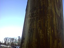
British Telecom posts are usually marked with the following information:[citation needed]
This list is incomplete; you can help by adding missing items. (August 2008) |
- 'BT' – to mark it as a British Telecom UK Pole (This can also be PO (Post Office) or GPO (General Post Office) depending on the age of the pole)
- a horizontal line marking 3 metres from the bottom of the pole
- the pole length, typically 8 to 10 metres,[24] and size. 9L is a 9 metres long, light pole, other letters used are 'M' (Medium) and 'S' (Stout).
- the year of treatment and therefore generally the year of installation (e.g. the pole in the picture was treated in 2003)
- the batch and type of wood used
- A date of the last official inspection
- An alphanumeric designation e.g. DP 242 where DP is an initialism of Distribution Point
- If relevant, a red D plate meaning 'Dangerous' and indicating that the pole was structurally unsafe to climb or due to its proximity to other hazards[25]
The date on the pole is applied by the manufacturer and refers to the date the pole was "preserved" (treated to withstand the elements).
In the United States, utility poles are marked with information concerning the manufacturer, pole height, ANSI strength class, wood species, original preservative, and year manufactured[26] (vintage) in accordance with ANSI standard O5.1.2008.[27] This is called branding, as it is usually burned into the surface; the resulting mark is sometimes called the "birth mark". Although the position of the brand is determined by ANSI specification, it is essentially just below "eye level" after installation. A rule of thumb for understanding a pole's brand is the manufacturer's name or logo at the top with a two-digit date beneath (sometimes preceded by a month).
Below the date is a two-character wood species abbreviation and one- to three-character preservative. Some wood species may be marked "SP" for southern pine, "WC" for western cedar, or "DF" for Douglas fir. Common preservative abbreviations are "C" for creosote, "P" for pentachlorophenol, and "SK" for chromated copper arsenate (originally referred to salts type K). The next line of the brand is usually the pole's ANSI class, used to determine maximum load; this number ranges from 10 to H6 with a smaller number meaning higher strength. The pole's height (from butt to top) in 5-foot increments is usually to the right of the class separated by a hyphen, although it is not uncommon for older brands to have the height on a separate line. The pole brand is sometimes an aluminum tag nailed in place.
Before the practice of branding, many utilities would set a 2- to 4-digit date nail into the pole upon installation. The use of date nails went out of favor during World War II due to war shortages but is still used by a few utilities. These nails are considered valuable to collectors, with older dates being more valuable, and unique markings such as the utilities' name also increasing the value. However, regardless of the value to collectors, all attachments on a utility pole are the property of the utility company, and unauthorized removal is a misdemeanor or felony.[28] (California state law cited as example)
Coordinates on pole tags edit
A practice in some areas is to place poles on coordinates upon a grid. The pole at right is a Delmarva Power pole located in a rural area of the state of Maryland in the United States. The lower two tags are the "X" and "Y" coordinates along said grid. Just as in a coordinate plane used in geometry, X increases as one travels east and Y increases as one travels north. The upper two tags are specific to the sub transmission section of the pole; the first refers to the route number, the second to the specific pole along the route.
However, not all power lines follow the road. In the British region of East Anglia, EDF Energy Networks often add the Ordnance Survey Grid Reference coordinates of the pole or substation to the name sign.
In some areas, utility pole name plates may provide valuable coordinate information: a poor man's GPS.[29][30][31]
-
 The tags on a Delmarva Power subtransmission pole located in Crisfield, Maryland, United States. The faded tag reads "733"
 -
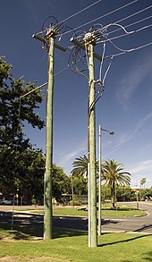
 A utility pole replacement in Saugus, Massachusetts, United States
 -
 Tag and marking on the bottom of a wooden utility pole before it is installed


Pole route edit
A pole route (or pole line in the US) is a telephone link or electrical power line between two or more locations by way of multiple uninsulated wires suspended between wooden utility poles. This method of link is common especially in rural areas where burying the cables would be expensive. Another situation in which pole routes were extensively used were on the railways to link signal boxes. Traditionally, prior to around 1965, pole routes were built with open wires along non-electrical operated railways; this necessitated insulation when the wire passed over the pole, thus preventing the signal from becoming attenuated.
At electrical operated railways, pole routes were usually not built as too much jamming from the overhead wire would occur. To accomplish this, cables were separated using spars with insulators spaced along them; in general four insulators were used per spar. Only one such pole route still exists on the UK rail network, in the highlands of Scotland. There was also a long section in place between Wymondham, Norfolk and Brandon in Suffolk, United Kingdom; however, this was de-wired and removed during March 2009.
Environmental impact edit
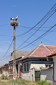
Utility poles are used by birds for nesting and to rest on.[32][33] Utility poles and related structures are regarded by some to be a form of visual pollution[citation needed]. Many lines are placed underground for this reason, in places of high population density or scenic beauty that justify the expense. Architects design some pylons to be pretty, thus avoiding visual pollution[citation needed].
Some chemicals used to preserve wood poles including creosote and pentachlorophenol are toxic and have been found in the environment[citation needed].
The considerable improvement in weathering resistance offered by creosote infusion has long-term drawbacks. In recent years, concerns have been raised about the toxicity of creosote-treated wood waste, such as utility poles. Specifically, their biodegradation can release phenolic compounds in soil, which are considered toxic. Research continues to explore methods to render this waste safe for disposal.[34]
Historically, pole-mounted transformers were filled with a polychlorinated biphenyl (PCB) liquid. PCBs persist in the environment and have adverse effects on animals.
See also edit
- Caber toss, a sport involving the throwing of large poles.
- Lamppost
- Oppenheimer pole
- Public utility
- Stobie pole
- Traction current pylon
- High voltage electricity pylon
- Anderson power pole
References edit
- ^ "Choosing the Right Materials for Pole Upgrades". Utilities One. Archived from the original on 2024-02-21. Retrieved 2024-02-21.
- ^ "What is a Power Pole? Information on Power Poles in Australia". 2022-11-02. Retrieved 2024-02-21.
- ^ Barber, Katherine, ed. (1998). The Canadian Oxford dictionary. Toronto; New York: Oxford University Press. p. 695. ISBN 0-19-541120-X.
- ^ "Why are overhead transmission lines not insulated?". www.electricalclassroom.com. 2020-07-17. Retrieved 2024-02-21.
- ^ a b Grigsby, Leonard L. (2001). The Electric Power Engineering Handbook. USA: CRC Press. ISBN 0-8493-8578-4. Archived from the original on 2016-04-28.
- ^ a b c d e "What's on a utility pole?". Consumer Assistance. Florida Public Service Commission. 2008. Archived from the original on 2016-02-25. Retrieved 2008-10-24.
- ^ "PMCPOLE.COM" (PDF). www.pmcpole.com. Archived (PDF) from the original on 2011-07-15.
- ^ "PMCPOLE.COM" (PDF). www.pmcpole.com. Archived (PDF) from the original on 2009-01-14.
- ^ "PMCPOLE.COM" (PDF). www.pmcpole.com. Archived (PDF) from the original on 2009-01-14.
- ^ Graham, Rex (July 24, 2014). "Resilient Woodpeckers hard to knock – or stop". Birdsnews.com. Archived from the original on April 4, 2016. Retrieved July 25, 2014.
- ^ Rasheed, Rizwan; Javed, Hajra; Rizwan, Asfra; Afzaal, Muhammad; Ahmad, Sajid Rashid (April 2023). "Eco-sustainability analysis of precast-concrete utility poles manufacturing–A case study from Pakistan". Heliyon. 9 (4): e14976. Bibcode:2023Heliy...914976R. doi:10.1016/j.heliyon.2023.e14976. ISSN 2405-8440. PMC 10121627. PMID 37095914.
- ^ "Granite Telegraph Poles in Switzerland." Archived 2016-06-02 at the Wayback Machine Popular Mechanics, December 1911, p. 851.
- ^ GR-3174, Generic Requirements for Hardware Attachments for Utility Poles
- ^ GR-3159, Generic Requirements for Fiber-Reinforced Composite (FRC), Concrete, and Steel Utility Poles
- ^ a b Kieve, Jeffrey L., The Electric Telegraph: A Social and Economic History, David and Charles, 1973 OCLC 655205099.
- ^ Nomination for Engineering Heritage Recognition: The Overland Telegraph Line 'Joining Point', Frews Pond, Northern Territory Archived 2014-09-11 at the Wayback Machine, Engineers Australia, June 2012.
- ^ McMullen, Ron, "The Overland Telegraph", The Australian Telegraph Office (CD ROM).
- ^ Rob Linn, ETSA – The Story of Electricity in South Australia, pp. 38–39, 1996.
- ^ ""Treated to refusal" does not meet the requirements of the international building codes" (PDF). Western Wood Preserver's Institute. Archived (PDF) from the original on August 12, 2016. Retrieved October 13, 2016.
- ^ James A. Taylor Timber Products Specialist Rural Electrification Administration U.S. Department of Agriculture Washington, D.C. (1978). "Pole Maintenance-Its Need and Its Effectiveness" (PDF). American Wood Preservers' Association. Archived (PDF) from the original on 2011-07-15.
- ^ Standard specifications for wood poles Archived 2012-02-24 at the Wayback Machine US Department of Agriculture, Forest Products Laboratory
- ^ "USDA Rural Development's Electric Programs - Bulletins". Archived from the original on 2009-01-15. Retrieved 2009-01-02.
- ^ "PMCPOLE.COM" (PDF). www.pmcpole.com. Archived (PDF) from the original on 2009-01-14.
- ^ David Chambers, "Every telegraph pole across UK now a potential outdoor small cell site" Archived 2022-01-23 at the Wayback Machine, ThinkSmallCell, 23 October 2014.
- ^ "GPO / British Telecom Telephone poles". www.britishtelephones.com. 2011-10-29. Archived from the original on 2017-04-24. Retrieved 2016-11-27.
- ^ "PMCPOLE.COM" (PDF). www.pmcpole.com. Archived (PDF) from the original on 2009-01-14.
- ^ "ANSI-American National Standards Institute". www.ansi.org. Archived from the original on 2008-08-28.
- ^ "Malicious Injuries to Railroad Bridges, Highways, Bridges, and Telegraphs". leginfo.legislature.ca.gov. Retrieved 2019-10-11.
- ^ "Taiwan Power Company grid – OSGeo". wiki.osgeo.org. Archived from the original on 2008-12-11.
- ^ "Understanding coordinates on utility pole numbers". Archived from the original on 2007-09-27. A Taiwan Power Company example; zh:電力座標
- ^ "How to read those little metal plates on Hydro pol". Archived from the original on 2013-06-05. A British Columbia, Canada example;
- ^ "Bird Nests on Power Poles". www.aplic.org. Retrieved 2024-02-21.
- ^ "Why Do Birds Sit On Power Lines? (Everything Explained)". Birdfact. Retrieved 2024-02-21.
- ^ Mateus, E.; Zrostlikova, J.; Gomes da Silva, M.D.R; Ribeiro, A.; Marriott, P. (2010). "Electrokinetic removal of creosote from treated timber waste: a comprehensive gas chromatographic view". Journal of Applied Electrochemistry. 40 (6): 1183–1193. doi:10.1007/s10800-010-0089-7. S2CID 97862454.
External links edit
- The Telegraph Pole Appreciation Society
- Article on Utility-Telecom Joint Use of Poles
- Many photographs Archived 2016-08-07 at the Wayback Machine
- Photographs of Various U.S. Utility Poles
- Hungarian Telephone Poles
- Utility Poles @ Ann's Garden
- Wood Utility Pole Inspection Methods Archived 2016-03-04 at the Wayback Machine
- A photo collection of pole routes throughout the UK and abroad
- American Wood Protection Association
- USDA Rural Development's Electric Programs Archived 2012-10-16 at the Wayback Machine
- GR-60, Generic Requirements for Wooden Utility Poles