


Summary
A variable-sweep wing, colloquially known as a "swing wing", is an airplane wing, or set of wings, that may be swept back and then returned to its original straight position during flight. It allows the aircraft's shape to be modified in flight, and is therefore an example of a variable-geometry aircraft.
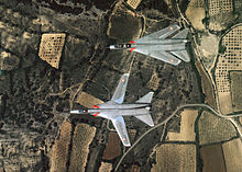

A straight wing is most efficient for low-speed flight, but for an aircraft designed for transonic or supersonic flight it is essential that the wing be swept. Most aircraft that travel at those speeds usually have wings (either swept wing or delta wing) with a fixed sweep angle. These are simple and efficient wing designs for high speed flight, but there are performance tradeoffs. One is that the stalling speed is increased, necessitating long runways (unless complex high-lift wing devices are built in). Another is that the aircraft's fuel consumption during subsonic cruise is higher than that of an unswept wing. These tradeoffs are particularly acute for naval carrier-based aircraft. A variable-sweep wing allows the pilot to use the optimum sweep angle for the aircraft's current speed, slow or fast. The more efficient sweep angles available offset the weight and volume penalties imposed by the wing's mechanical sweep mechanisms. Its greater complexity and cost make it practical mostly for military aircraft.
A number of aircraft, both experimental and production, were introduced between the 1940s and the 1970s. The majority of production aircraft to be furnished with variable-sweep wings have been strike-oriented aircraft, such as the Mikoyan-Gurevich MiG-27, Tupolev Tu-22M, and Panavia Tornado. The configuration was also used for a few fighter/interceptor aircraft, including the Mikoyan-Gurevich MiG-23, Grumman F-14 Tomcat, and the Panavia Tornado ADV. From the 1980s onwards, the development of such aircraft were curtailed by advances in flight control technology and structural materials which have allowed designers to closely tailor the aerodynamics and structure of aircraft, removing the need for variable sweep angle to achieve the required performance; instead, wings are given computer-controlled flaps on both leading and trailing edges that increase or decrease the camber or chord of the wing automatically to adjust to the flight regime; this technique is another form of variable geometry.
Characteristics edit
Variable sweep edit
A straight, unswept wing experiences high drag as it approaches the speed of sound, due to the progressive buildup of sonic shockwaves. Sweeping the wing at an angle, whether backwards or forwards, delays their onset and reduces their overall drag. However it also reduces the overall span of a given wing, leading to poor cruise efficiency and high takeoff and landing speeds.
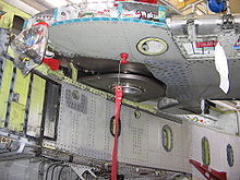
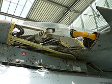
A fixed wing must be a compromise between these two requirements. Varying the sweep in flight allows it to be optimised for each phase of flight, offering a smaller aircraft with higher performance. However it has disadvantages which must be allowed for. As the wing sweeps its centre of lift moves with it. Some mechanism, such as a sliding wing root or larger tail stabiliser, must be incorporated to trim out the changes and maintain level flight. The added weight of the sweep and trim mechanisms eat into the performance gains, while their complexity adds to cost and maintenance.
By moving the wing pivots outboard and only sweeping part of the wing, the trim changes are reduced, but so too is the variation in span and accompanying operational flexibility.
Wing controlled aerodyne edit
British engineer Barnes Wallis developed a radical aircraft configuration for high-speed flight, which he regarded as distinct from the conventional fixed-wing aeroplane and called it the wing controlled aerodyne. His previous work on the stability of airships had impressed on him the high control forces that could be exerted on the body of an aircraft, through very small deflections. He conceived of a simple ichthyoid (fish-like) fuselage with a variable wing. No other control surfaces were needed. Subtle movements of the wings were able to induce the small deflections which controlled the direction of flight, while trim was maintained by adjusting the angle of sweep to compensate for the varying position of the centre of lift at different speeds.[1][2]
For supersonic flight a delta-planform lifting body is more suitable than a simple ichthyoid. A conflict also arises between the wing sweep angle necessary for trim and the optimal angle for supersonic cruise. Wallis resolved this by moving mass, typically the engines, out to the wing tips and swivelling them as the wing swept in order to maintain the thrust line. In the asymmetric engine-out condition, the remaining engines could be swivelled to divert the thrust line closer to the centre of pressure and reduce the asymmetry to manageable levels.[1]
Asymmetric sweep edit
It is not necessary to sweep the port and starboard wings in the same sense - one can be swept back and the other forward, as in the oblique wing.
Varying the sweep asymmetrically by small amounts was also fundamental to the principle of the wing controlled aerodyne.
History edit
Origins edit


The earliest use of variable sweep was to trim the aeroplane for level flight. The Westland-Hill Pterodactyl IV of 1931 was a tailless design whose lightly swept wings could vary their sweep through a small angle during flight.[3] This allowed longitudinal trim in the absence of a separate horizontal stabiliser.[4] The concept would later be incorporated in Barnes Wallis's wing-controlled aerodyne.[5]
During the Second World War, researchers in Nazi Germany discovered the advantages of the swept wing for transonic flight, and also its disadvantages at lower speeds. The Messerschmitt Me P.1101 was an experimental jet fighter which was, in part, developed to investigate the benefits of varying wing sweep.[6] Its sweep angle mechanism, which could only be adjusted on the ground between three separate positions of 30, 40, and 45 degrees, was intended for testing only, and was unsuitable for combat operations.[6] However, by Victory in Europe Day, the sole prototype was only 80 per cent complete.[7][8]
Development edit
Following the end of the conflict, the partially complete P.1101 was recovered and transported to the United States, where it was studied in depth by Bell Aircraft. However, due to a lack of documentation as well as some structural damage sustained,[9][8] Bell decided against completing the aircraft itself. Instead, a close copy, known as the Bell X-5, was constructed with wings that enabled the sweep angle to be altered mid-flight. As the wing swept back, the root also slid forwards, maintaining the centre of lift in a constant position.[10] A variable-sweep wing of this sliding type was flown on the prototype Grumman XF10F Jaguar in 1952. However, flight testing of the F10F proved to be unacceptable, albeit for other factors such as a lack of engine power and considerable controllability issues.[11][12]
During the late 1940s, British engineer L. E. Baynes started studying the variable sweep wing. He devised a method of varying the tail geometry as well in order to stabilise the centre of lift; no sliding mechanism was necessary, instead, the wing wake interacted with the variable tail to effect the necessary trim changes. During 1949 and 1951, Baynes filed patent applications associated with this work.[13][14] While the design reached the physical modelling stage and was subject to a complete round of wind tunnel tests, the British Government failed to provide financial backing for the work, allegedly due to budget constraints at the time.[citation needed]
Independently from Baynes, British engineer Barnes Wallis was also developing a more radical variable-geometry concept, which he called the wing controlled aerodyne, to maximise the economy of high-speed flight. His first study was the Wild Goose project.[5] Subsequently, Barnes devised the Swallow,[5] a blended wing tailless aircraft, which was envisioned to be capable of making return flights between Europe and Australia within ten hours. Later on, the Swallow was increasingly viewed as a potential supersonic successor to the subsonic Vickers Valiant, one of the RAF's V bombers.[15] During the 1950s, several modes of the Swallow were subjected to promising tests, including a six-foot scale model, at speeds of up to Mach 2. However, in 1957, British government decided to withdraw backing from many aeronautical programs, including Wallis' work.[16][15]
Despite this lack of backing, the Swallow attracted international attention for some time. During late 1958, research efforts were temporarily revived through cooperation with the Mutual Weapons Development Programme of NATO, under which all of Wallis' variable geometry research was shared with the Americans.[15] According to aviation author James R. Hansen, American aerospace engineer John Stack was enthusiastic on the concept, as were numerous engineers at NASA; however, the United States Department of Defense was opposed to committing any resources to the project.[17] Wallis collaborated with NASA's Langley Laboratory on a design study for a variable-sweep fighter. Although it used the pivot mechanism he had developed, NASA also insisted on implementing a conventional horizontal stabiliser to ease the issues of trim and manoeuvrability. Although it was no longer the wing-controlled aerodyne that Wallis envisaged, it would prove a more practical solution than either his or Bell's. Swallow research led to several new configurations, including the adoption of a compact folding tail section and canards.[18]
Barnes' work inspired a number of further studies, including a wing controlled aerodyne in response to OR.346 for a supersonic STOL fighter-bomber, then as BAC two further submissions: the Type 583 to meet Naval ER.206 and Type 584 to meet NATO NBMR.3, both also being V/STOL requirements.[1] In 1960, Maurice Brennan joined Folland Aircraft as its chief engineer and director; he soon set about harnessing his experience of variable-geometry wings.[19] Accordingly, such a wing was combined with the firm's Folland Gnat light fighter for two different concepts – one tailless and one using with a conventional tail – for a multipurpose fighter/strike/trainer, designated as the Fo. 147. It had a unique mechanism for wing sweep that combined tracks on the fuselage sides and the underside of the wings, which was actuated by hydraulically-driven ball screws positioned at the wing's inner ends.[20] The wings could be swept from 20 degrees to 70 degrees; at the 70-degree position, longitudinal control was maintained by wing tip-mounted elevons, while this was provided by a retractable canard arrangement when swept at the 20-degree position, using full auto-stabilisation. By providing trimming functionality via the canard, the necessity of a large tailplane was eliminated.[21] The Fo. 147 was claimed to have been capable of speeds in excess of Mach 2, being limited by the heat buildup generated by high speed flight.[22] Ultimately, the concept would not be developed to the prototype stage while the RAF showed little interest the prospective variable geometry trainer.[22]
Production edit
During the 1960s, the first programmes to produce mass production variable-sweep aircraft commenced. In the United States, such a configuration for the TFX (Tactical Fighter Experimental) program, which resulted in the development of the General Dynamics F-111, a sizable twin-engined aircraft intended to perform multiple roles.[23][24] The F-111 is the first production aircraft to feature a variable-geometry wing and it, along with other systems such as terrain following radar and turbofan engines outfitted with afterburners, were innovative technologies for the era.[25][26]
Despite this head start in the field, development of the F-111 was protracted; flight testing of the F-111A model only ended in 1973.[27] During 1968, cracks were discovered in the F-111's wing attach points, the issue also has been attributed with the loss of an F-111 in the following year.[28] Accordingly, the attach points were structurally redesigned and subject to intensive testing of both the design and manufacturing quality.[29] The F-111B, intended for the US Navy, was cancelled in 1968 due the aircraft's weight and performance issues, as well as its inadequacies for the service's fighter requirements.[30][31] Several variants, such as the FB-111A strategic bomber model, featured elongated wings to give a greater range and load-carrying capability.[32] The F-111's wing featured pivoting pylons (two under each wing) which automatically adjusted to the sweep angle. Subsequent swing-wing aircraft, such as the Panavia Tornado and Sukhoi Su-24, would also be similarly equipped.[citation needed]
In the Soviet Union, military planners had also formulated similar requirements, which led to TsAGI, the Soviet aerodynamics bureau, performing extensive studies into variable geometry wings. TsAGI evolved two distinct designs, differing mainly in the distance (expressed as a percentage of total wingspan) between the wing pivots. By adopting a wider spacing, this not only reduced the negative aerodynamic effects of changing wing sweep, but also provided a larger fixed wing section which could be used for landing gear or stores pylons. This could, in fact, be adapted to more-or-less existing airframes, which the Soviets accordingly did, such as with the Sukhoi Su-17 (based on the earlier swept wing Sukhoi Su-7). The limitation of the wide spacing, however, was that it reduced the benefits of variable geometry as much as it reduced their technical difficulties.[citation needed]
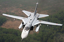
As such, producing new, "clean-sheet" Soviet designs remained desirable. For this, TsAGI devised a more narrowly-spaced arrangement somewhat similar to that of the F-111. This design was used, albeit at different scales, for the Mikoyan-Gurevich MiG-23 fighter and the Sukhoi Su-24 tactical bomber, both of which flew in prototype forms around the end of the 1960s and entering service during the early 1970s. During 1962, Tupolev's design team, recognising room for improvement on the recently introduced Tupolev Tu-22 bomber, begun work on an extensively redesigned derivative that incorporated a variable geometry wing, intended to address the Tu-22's poor handling characteristics more so than bolstering its efficiency at high speeds.[33][34] As of 2014[update] more than 100 Tupolev Tu-22M strategic bombers are in use.[35]
During the late 1950s and early 1960s, Britain was developing the BAC TSR-2, a supersonic low-level strategic bomber. Later variants of the type would have been fitted with variable-geometry wings.[36] However, on 1 April 1965, development of the TSR-2 was terminated during the flight testing phase primarily due to the programme's spiralling costs.[37][38] To replace the TSR-2, the Air Ministry initially placed an option for the American General Dynamics F-111K;[39][40] while the F-111K was promoted as being cheaper,[41] this too was terminated during January 1968 on grounds of cost.[42]
Following the TSR-2's cancellation, BAC moved their variable-geometry work to Warton, there submitting the P.45 light attack/trainer to AST 362. This work fed into a joint Anglo-French programme to develop a variable geometry strike aircraft – the Anglo French Variable Geometry Aircraft (AFVG). This multirole aircraft was to be equipped with a variable geometry wing and was intended to perform the strike, reconnaissance, and interceptor roles.[43][44] However, as early as 1966, the French aircraft manufacturer Dassault began to actively undermine the AFVG, as it was working on two competing in-house projects: the variable geometry Mirage G and the Mirage F1.[45] According to aviation author Derek Wood, both Dassault and the French Air Force were unenthusiastic participants in the AFVG, the former wanting to pursue its own indigenous variable geometry aircraft, while the latter had determined that the type did not align with its future equipment plans.[44] In June 1967, the French government announced their withdrawal from the AFVG project ostensibly on the grounds of cost.[N 1][47]

Despite the AFVG programme's collapse, the design was revamped by BAC into a larger strike-oriented variable geometry aircraft. Holding contracts were issued to BAC to support the project, which had been re-designated as the United Kingdom Variable Geometry (UKVG) aircraft.[48][49] In November 1967, BAC issued a brochure on the UKVG proposal; various proposals would be issued to cover the use of multiple different engines. The quick production of a demonstrator aircraft, powered by a pair of Rolls-Royce/MAN Turbo RB153 turbofan engines, was also mooted.[49] As solely funding for the UKVG was unrealistic, the British government pursued partners within its fellow NATO members,[N 2] promoting the concept of developing and procuring a common NATO strike aircraft. In July 1968, a memorandum of understanding was signed between Britain, West Germany, Italy, the Netherlands, Belgium, and Canada.[51] This memorandum eventually led to the launch of the multinational Multi-Role Combat Aircraft (MRCA) project, which successfully produced a variable geometry aircraft for the strike, reconnaissance, and interception missions in the form of the Panavia Tornado.[50][52][53]
Following the AFVG effort, Dassault Aviation constructed a prototype fighter, the Mirage G, completing two aircraft, the Mirage G4 and G8, in 1968.[54] Furthermore, Dassault also worked in cooperation with the American manufacturing interest Ling-Temco-Vought to develop the LTV V-507, which was submitted for US Navy's VFX project.[55] From the VFX submissions, the US Navy procured the Grumman F-14 Tomcat to replace the canceled F-111B fleet interceptor during the 1970s. The F-14 was a more nimble fighter than the F-4 Phantom II and, unlike the F-111, its variable-sweep wings automatically adjusted over its speed range, and could be moved even during turns. Furthermore, the wings could be swept forward for tight "bat" turns in close quarters aerial combat, as well as rearwards for dash speeds.[56][57]
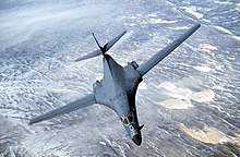
Rockwell adopted variable geometry for the much larger Advanced Manned Strategic Bomber (AMSA) program that produced the B-1 Lancer bomber, intended to provide an optimum combination of high-speed cruising efficiency and fast, supersonic penetration speeds at extremely low level. The B-1's variable-sweep wings provide a relatively high level of lift during takeoff and landing, while also generating little drag during a high-speed dash.[58] When the wings were set to their widest position the aircraft had considerably better lift and power than the B-52, allowing the B-1 to operate from a much wider variety of bases.[58] Rockwell submitted its proposal in January 1970, competing against bids by Boeing and General Dynamics.[59][60] The B-1's development was authorised in October 1981 as a stopgap between the increasingly vulnerable B-52 and the more capable Advanced Technology Bomber (ATB).[58][61] Initial operational capability was reached on 1 October 1986 and the B-1B was placed on nuclear alert status.[62][63]
The Soviet Union also opted to develop a large strategic bomber equipped with variable geometry wings. During the early 1970s, Tupolev's design, which was initially designated Aircraft 160M, featured a lengthened blended wing layout and incorporated some elements of the Tu-144, competed against the Myasishchev M-18 and the Sukhoi T-4 designs.[64] Designated as the Tupolev Tu-160, it entered operational service with the 184th Guards Heavy Bomber Regiment located at Pryluky Air Base, Ukrainian SSR, during April 1987.[65] The aircraft is the largest and heaviest combat aircraft, the fastest bomber in use and the largest and heaviest variable-sweep wing airplane to have ever flown as of 2020.[66]
Obsolescence edit

A variable-sweep wing was selected as the winning design used by Boeing's entry in the FAA's study for a supersonic transport, the 2707. However it evolved through several configurations during the design stage, finally adding a canard, and it eventually became clear that the design would be so heavy that it would be lacking sufficient payload for the fuel needed. The design was later abandoned in favor of a more conventional tailed delta wing.[67]
The advent of relaxed stability flight control systems in the 1970s negated many of the disadvantages of a fixed-wing configuration. No new variable-sweep wing aircraft have been built since the Tu-160 (produced until 1992).
In 2015, the Russian Ministry of Defence announced plans to restart Tu-160 production, citing the aging of the current aircraft and likely protracted development of its eventual replacement, the PAK DA project.[68] Production restarted in 2021, marking the first new variable sweep airframes to be produced in 29 years.[69][70]
List of variable-sweep aircraft edit
| Type | Country | Class | Role | Date | Status | No. | Notes |
|---|---|---|---|---|---|---|---|
| Bell X-5 | USA | Jet | Research | 1951 | Prototype | 2 | Development of the Messerschmitt P.1101 (qv) allowing sweep variation in-flight. |
| Dassault Falcon 75 | France | Jet | Transport | 1968 | Project | 0 | [71] |
| Dassault Mirage G | France | Jet | Fighter | 1967 | Prototype | 3 | |
| General Dynamics F-111 | USA | Jet | Fighter-bomber | 1964 | Production | 563 | |
| Grumman XF10F Jaguar | USA | Jet | Fighter | 1952 | Prototype | 1 | 2nd example not flown. |
| Grumman F-14 Tomcat | USA | Jet | Fighter | 1970 | Production | 712 | |
| Hawker Siddeley P.1017 | UK | Jet | Fighter | 1962 | Project | 0 | VTOL capable strike fighter concept.[72][73] |
| Messerschmitt P.1101 | Germany | Jet | Research | 1945 | Project | 0 | 1 unfinished airframe. Wings variable to 3 pre-set positions only while on the ground. |
| Mikoyan-Gurevich MiG-23 | USSR | Jet | Fighter | 1967 | Production | 5,047 | |
| Mikoyan MiG-27 | USSR | Jet | Attack | 1970 | Production | 1,075 | Development of the MiG-23. |
| Panavia Tornado (MRCA) | International | Jet | Multirole | 1974 | Production | 992 | |
| Rockwell B-1 Lancer | USA | Jet | Bomber | 1974 | Production | 104 | |
| Sukhoi Su-17, 20 & 22 | USSR | Jet | Fighter-Bomber | 1966 | Production | 2,867 | |
| Sukhoi Su-24 | USSR | Jet | Attack | 1970 | Production | 1,400 (approx) | |
| Tupolev Tu-22M | USSR | Jet | Bomber | 1969 | Production | 497 | |
| Tupolev Tu-160 | USSR | Jet | Bomber | 1981 | Production | 36 | |
| Vickers Wild Goose | UK | UAV | Research | 1950 | Prototype | 1 | Designed by Barnes Wallis.[74] |
| Vickers Swallow | UK | Jet | Airliner | 1957 | Project | 0 | Designed by Barnes Wallis. Small-scale test UAV flown. |
| Westland-Hill Pterodactyl IV | UK | Propeller | Private | 1931 | Prototype | 1 | Variable 4.75° for trim.[75] |
| NASA AD-1 | USA | Jet | Research | 1979 | Prototype | 1 | Unique wing that could be pivoted obliquely from zero to 60 degrees during flight |
See also edit
References edit
Notes edit
- ^ According to aviation publication Flight International, Dassault had gained valuable data on variable-geometry configurations from the AFVG programme and may have used the excuse of cost issues in order to divert funds and data to their own VG projects.[46]
- ^ Belgium, Canada, Italy, the Netherlands and West Germany were approached.[50]
Citations edit
- ^ a b c Wood, 1975.
- ^ Morpurgo, 1981.
- ^ Meekcoms and Morgan 1994, p. 143.
- ^ Lukins A H, The Book of Westland aircraft, Aircraft (Technical) Publications Ltd.
- ^ a b c "Barnes Wallis Supersonics, Wild Goose". Archived from the original on 10 October 2018. Retrieved 23 September 2018.
- ^ a b Christopher 2013, pp. 157–160.
- ^ Hirschel, Prem and Madelung 2012, p. 336.
- ^ a b Ford 2013, p. 224.
- ^ Myrha, David (1999). The Messerschmitt Me P.1101. Atglen, PA: Schiffer Pub. Ltd. ISBN 0-7643-0908-0. [page needed]
- ^ Abzug and Larrabee, Airplane Stability and Control: Second Edition. ISBN 978-0-521-02128-9. p. 244.
- ^ Winchester 2005, p. 295.
- ^ DeMeis 1976, p. 32.
- ^ UK Patent GB664058A, Espacenet
- ^ UK Patent GB713525A, Espacenet
- ^ a b c Wood 1975, pp. 189-191.
- ^ "Swing Wing." Archived 6 April 2007 at the Wayback Machine The Barnes Wallis Memorial Trust. Retrieved: 14 May 2013.
- ^ Hansen 2004, pp. 129-130.
- ^ Hansen 2004, pp. 130-132.
- ^ Wood 1975, p. 197.
- ^ Wood 1975, pp. 198.
- ^ Wood 1975, pp. 198–199.
- ^ a b Wood 1975, p. 199.
- ^ Eden 2004 pp. 196–197.
- ^ Price, Bem (18 September 1966). "Capital still buzzing whether TFX a colossal blunder". Eugene Register-Guard. (Oregon). Associated Press. p. 5A.
- ^ Logan 1998, p. 14.
- ^ Miller 1982, pp. 17, 19.
- ^ Logan 1998, p. 32.
- ^ "F-111 problems return to plague President". Reading Eagle. (Pennsylvania). Associated Press. 13 January 1970. p. 8.
- ^ Miller 1982, pp. 31, 47.
- ^ Boyne 2002, p. 252.
- ^ Thomason 1998, pp. 52–53.
- ^ Miller 1982, pp. 38–43.
- ^ Kandalov & Duffy 1996, p. 124.
- ^ Eden, Paul, ed. "Tupolev Tu-22/22M". Encyclopedia of Modern Military Aircraft. London: Amber Books, 2004. ISBN 1-904687-84-9.
- ^ Hoyle, Craig (26 September 2014), "Kings of the swingers: Top 13 swing-wing aircraft", Flightglobal, Reed Business Information, archived from the original on 27 September 2014, retrieved 27 September 2014
- ^ Murray, Iain. "Bouncing-Bomb Man: the Science of Sir Barnes Wallis." Haynes, 2009. p. 191.
- ^ Conclusions of a Meeting of the Cabinet held at 10 am. 10 Downing Street, S.W.1, on Thursday, 1st April, 1965, CC(65)20, CAB/128/39. London: Public Record Office, 2010.
- ^ Conclusions of a Meeting of the Cabinet held at 10 Downing Street, S.W.1, on Thursday, 1st April, 1965, at 10 p.m., CC(65)21, CAB/128/39. London: Public Record Office, 2010.
- ^ Healey, D. W. The Need for an Option on the F-111A, C(65)58, CAB/129/121. London: Public Record Office, 2010.
- ^ DeWeerd, H.A. "P-3347: The 1966 Defense Review." The Rand Corporation, April 1966. Retrieved: 13 December 2010.
- ^ Wood 1986, p. 181.
- ^ Logan 1998, pp. 278–80.
- ^ "Anglo-French projects go ahead... The AFVG and its dual role." Flight via flightglobal.com, 26 January 1967.
- ^ a b Wood 1975, p. 202.
- ^ DeVore, Marc. "Making Collaboration Work: Examining Sub-Optimal Performance and Collaborative Combat Aircraft." allacademic.com. Retrieved: 2 February 2011.
- ^ "Military and Research." Flight via flightglobal.com, 1 June 1967. Retrieved: 29 January 2011.
- ^ Wood 1975, pp. 203–204.
- ^ Heron 2002, p. 11.
- ^ a b Wood 1975, p. 204.
- ^ a b "Obituary: Handel Davies." The Guardian, 24 May 2003. Retrieved: 29 January 2011.
- ^ Wood 1975, pp. 204, 206.
- ^ Wood 1975, p. 206.
- ^ Buttler, Tony. British Secret Projects: Jet Bombers Since 1949.[page needed]
- ^ Green 1972, p. 84.
- ^ Claude Carlier, Une formule aérodynamique gagnante. La grande aventure des «Mirage» à géométrie variable, 2, Le Fana de l’aviation, 537, août 2014.
- ^ Kress, Bob and RADM Gilchrist USNRet. "F-14D Tomcat vs. F/18 E/F Super Hornet." Archived 4 April 2009 at the Wayback Machine Flight Journal Magazine, February 2002 Issue. Quote: "dedicated air combat occurs at below about 0.8 because of high turning drag – an arena in which the F-14's 20-degree sweep is optimal ... it has only 36 percent of the F-14's payload/range capability."
- ^ "Fact file: F-14 Tomcat". 11 December 2002. Archived from the original on 30 March 2009. Retrieved 22 January 2009.
- ^ a b c Lee 2008, p. 13.
- ^ Pace 1998, pp. 22-23.
- ^ Kocivar, Ben. "Our New B-1 Bomber – High, Low, Fast, and Slow." Popular Science, Volume 197, Issue 5, November 1970, p. 86.
- ^ Coates, James. "Reagan approves B-1, alters basing for MX." Chicago Tribune, 3 October 1981. Retrieved: 28 July 2010.
- ^ Pace 1998, pp. 62, 69.
- ^ Jenkins 1999, p. 83.
- ^ Sergeyev, Pavel (30 April 2008). Белый лебедь [White Swan]. Lenta.ru (in Russian). Archived from the original on 17 July 2011. Retrieved 5 August 2009.
- ^ Miller, David (1998). The Cold War: A Military History (Pimlico 2001 ed.). London: John Murray, Random House. p. 162. ISBN 1-44813793-4.
- ^ "Largest military aircraft by weight, operational bomber". Guinness World Records. Archived from the original on 6 October 2018. Retrieved 29 December 2018.
- ^ "Boeing 2707 SST".
- ^ Stevenson, Beth (30 April 2015). "Russia to reestablish Tu-160 supersonic bomber production line". Flightglobal. Archived from the original on 17 December 2015. Retrieved 20 November 2015.
- ^ "Putin made decision to revive production of Tu-160M strategic bomber — Air Force commander". TASS. 28 May 2015. Archived from the original on 23 June 2015. Retrieved 20 November 2015.
- ^ "Вновь изготовленный Ту-160М совершил первый полет". rostec.ru. Retrieved 4 May 2023.
- ^ Roland de Narbonne; "Quand l'ingenier délire", Le Fana de l'Aviation, No. 461, April 2008. pp.66-69.
- ^ Hawker's Secret Projects: Cold War Aircraft That Never Flew By Christopher Budgen 2023, ISBN 9781399047906
- ^ "Проект штурмовика УВВП Hawker Siddeley P.1017 (Великобритания. 1962 год)". 22 May 2022.
- ^ Morpurgo, 1981. Date of first flight, p. 321.
- ^ Lukins, A.H.; The Book of Westland Aircraft, Aircraft (Technical) Publications Ltd, 1943 or 1944. pp.68-9.
Bibliography edit
- Boyne, Walter J (2002), Air Warfare: an International Encyclopedia, vol. 1, Santa Barbara, California: ABC-CLIO, ISBN 1-57607-345-9
- Christopher, John (1 June 2013). The Race for Hitler's X-Planes : Britain's 1945 Mission to Capture Secret Luftwaffe Technology. History Press. ISBN 978-0752464572.
- DeMeis, Richard. "No Room to Swing a Cat." Wings, Volume 6, No. 4, August 1976.
- Eden, Paul, ed. (2004), "General Dynamics F-111 Aardvark/EF-111 Raven", Encyclopedia of Modern Military Aircraft, London: Amber Books, ISBN 1-904687-84-9
- Ford, Roger (2013). Germany's Secret Weapons of World War II. London, United Kingdom: Amber Books. ISBN 9781909160569.
- Green, William. The Observer's Book of Aircraft. London. Frederick Warne & Co. Ltd., 1972. ISBN 0-7232-1507-3.
- Hansen, James R. (2004). The Bird Is on the Wing: Aerodynamics and the Progress of the American Airplane. Texas A&M University Press. ISBN 1-5854-4243-7 – via Google Books.
- Heron, Group Captain Jock. "Eroding the Requirement." The Birth of Tornado. London: Royal Air Force Historical Society, 2002. ISBN 0-9530345-0-X.
- Hirschel, Ernst Heinrich., Horst Prem and Gero Madelung. Aeronautical Research in Germany: From Lilienthal until Today. Springer Science & Business Media, 2012. ISBN 3-642-18484-7.
- Jenkins, Dennis R (1999). B-1 Lancer: The Most Complicated Warplane Ever Developed. New York: McGraw-Hill. ISBN 0-07-134694-5.
- Kandalov, Andrei; Duffy, Paul (1996). Tupolev – The Man and His Aircraft: The Man and His Aircraft. Society of Automotive Engineers. ISBN 1560918993.
- Lee, Tae-Woo (2008). Military Technologies of the World. Vol. 1. Santa Barbara, CA: ABC-CLIO. ISBN 978-0-275-99535-5.
- Logan, Don. General Dynamics F-111 Aardvark. Atglen, Pennsylvania: Schiffer Military History, 1998. ISBN 0-7643-0587-5.
- Meekcoms, K J; Morgan, E B (1994). The British Aircraft Specification File. Tonbridge, Kent, UK: Air-Britain. ISBN 0-85130-220-3.
- Miller, Jay. General Dynamics F-111 "Aardvark". Fallbrook, California: Aero Publishers, 1982. ISBN 0-8168-0606-3.
- Morpurgo, J.E. Barnes Wallis: A Biography. 2nd Edn, 1981. (1st Edn, Longmans, 1972).
- Pace, Steve (1998). Boeing North American B-1 Lancer. North Branch, MN: Specialty Press. ISBN 1-58007-012-4.
- Thomason, Tommy. Grumman Navy F-111B Swing Wing (Navy Fighters No. 41). Simi Valley, California: Steve Ginter, 1998. ISBN 0-942612-41-8.
- Winchester, Jim. The World's Worst Aircraft: From Pioneering Failures to Multimillion Dollar Disasters. London: Amber Books Ltd., 2005. ISBN 1-904687-34-2.
- Wood, Derek. Project Cancelled. Macdonald and Jane's Publishers, 1975. ISBN 0-356-08109-5.